I completely agree. It is really great that you get to have such in depth peer review from Jono too. That is great. I have learned a lot (half learned, at most) just reading through the feedback.
I should design another board for no reason. I have always enjoyed the process.
Yes, watching this all transpire and not even a board was made yet, but the revisions that have happened! IT was insane! This place is on a whole new level!!!
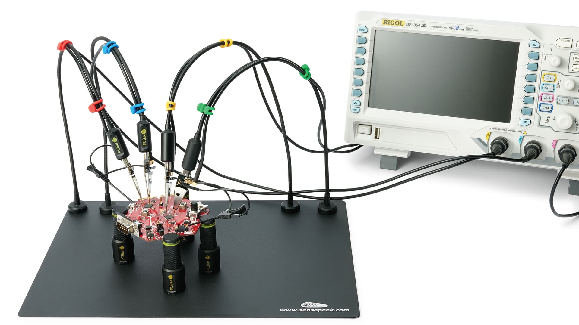
There are a ton of different things like that around, ranging from super basic DIY stuff to quite hardcore professional products. Depending on the scenario they can be a really useful tool to have.
The thing is, they’re really valuable when you’re trying to reverse engineer something or if you’re working on something super small.
For the vast majority of what I end up doing, I have enough space to just put proper test points on, though. These can have pins soldered into them for connection to something like a scope’s digital lines, a logic analyzer, bus pirate, USB-FTDI cable, whatever or loop test points like a Keystone 5001 for connection to a scope probe directly. For something like this board, almost every single connection is going to a header which makes it easy to probe without a test array like that.
So they’re neat and have been super useful in a few circumstances, but honestly I end up using it when I’ve forgotten to put a test point on something or I’m trying to reverse engineer something that uses plain pad style test points.
I have a couple of designs where I’ve used 1mm diameter pads as test points, but in future I think I’ll go back to something like the SMT testpoints that Keystone do. Best case, you reflow the test point on and can clip a grabber to them. Worst case you don’t bother with the test points and can still use something like the probing setup.
Honestly, there’s not ‘that’ much difference between the moving/layout stuff that you were doing and the simpler end of digital design. It’s really just hooking lines up to GPIO, making sure there are passives in the right places to do some filtering where needed, etc. We’ve already talked through some of the key basics of electronic design and it’s possible to go quite a distance with those if you’re willing to spend the time to think through things. Most of it comes down to ‘what happens in this state? What happens in this other state? What happens when it goes between them? Is any of that ‘bad’ according to a few basic rules?’ etc.
Download the step files is definitely a helpful ability to have. We make a lot of use of that when making larger assemblies and designing heat-sinks etc. I have one open that I’m reviewing now.
It has probably 40 parts total, including injection moulded plastic parts, cast and machined aluminium parts, sealed automotive connector assemblies, cable assemblies, a couple of different PCBs, pre-cast coil assemblies, multiple o-rings, coolant barbs, all sorts.
I tend to try to make all my PCBs with as much mechanical detail on them in terms of 3D models, including things that get screwed/bolted onto the PCB, the mating connectors for headers, just whatever I can. That way it’s relatively easy to bring all of that in as an immutable object into 3D mechanical CAD and start packaging stuff around it.
Go for it! I’m always floating around if you’d like feedback or assistance.
That’s the goal. It’s a hell of a lot cheaper/easier to rework a design and fix potential issues when it only exists in CAD. I think the crazy thing about how cheap the manufacture/assembly process has gotten is that it’s making it much more possible to just iterate rapidly and fix issues in the next revision, which makes it possible to break away from the ‘do 5 reviews and get signoff from 10 different people’ approach. I guess the counterpoint is that it’s still slow to test and find those issues, so there’s still a lot of power and value in pre-release review, but a lot less than there once was when this whole process would have been more expensive and slower.
Hell, 24 hour PCBs used to cost us thousands of dollars, minimum, and 1 week turn was a couple hundred in fixed costs for a board that size, regardless of manufacturing quantity. Assembly was similar, probably $1k+ for the fixed costs. It was very difficult to do a run of any size for much less than $10k. Insanity
All i can say is WOW and THANK YOU so much for all you smart people benefiting us with your time and knowledge.
I have said it before and i will say it again this is an amazing forum.
Not as many buttons/dials/features as what Jamie’s planning, but…
Adafruit do a product of the week Livestream with 50% discount for a specific product (Tues 1pm - ~1:45pm PST). This week’s stream starts in ~20mins and features an I2C based game pad inspired board with 2 axis analog and 6 buttons. You’ll pay more for shipping than the $3.75 this’ll cost, but people usually end up adding other stuff to their cart, e.g. ESP32 QT Py, stemma qt cable, maybe a rotary dial even…
No limitation except that I hadn’t thought of it. The gamepads have up to 4 configurable addresses so I suppose that means 4 game pads and an OLED can all be connected at the same time.
It’s also just a microcontroller acting as an I2C slave so could easily be expanded on to change the addressing or add additional ways of signaling address values if you wanted to go beyond 4 gamepads for some reason while keeping it compatible with the other Adafruit messaging stuff etc.
I just have to chime in, having worked (tangentially) with CAN devices. In environments CAN was designed for. And it is a beast. Both in terms of its reliability and how finicky it can be to get set up correctly. I briefly worked with a company that provided hardware and software for public transit systems. Specifically, dispatch to driver communications, route data information, on-board signage (internal and external), voice comms, emergency alerts, fare collection (on-board and kiosk/vending machine based), route and fleet management, etc., etc. The fun was getting all these devices to talk to each other over the fewest wires in an aggressively hostile environment: public transit systems, i.e., busses. I thought I had a reasonable idea about robust software design walking in to that job. But this was systems architecture in the truest sense. Heck, the fareboxes I was working with had two SOCs inside, one running a Linux derivative, the other Embedded Windows.
Yeah, for sure, CAN is definitely robust. I’d personally say RS485 has the edge on it simply by being low impedance in both mark and space states, but that comes with the burden of manually handling multi-master setup and no way to do arbitration. The biggest issues with CAN are poorly defined message timing due to the self-arbitration and relatively low bandwidth/poor line efficiency. Both of those can be managed without too much issue though.
The newer stuff on top of CAN like CANOpen gets pretty wild, as does the CAN over ethernet stuff.
Definitely know what you mean about the systems architecture nightmares. We’re in that situation at the moment. I think we’re at something like 8 controllers potentially, two of which will be running some form of RTOS, one which is a soft core on an FPGA, a few that are embedded DSP style microcontrollers doing the actual hardware control, etc. It’s amazing how much time can go into defining where even a relatively simple state machine will reside and where it will be passing information to/from.
I did a bunch of systems architecture and can/J1939 messaging design on a bunch of autonomous 15t+ army trucks and your system sounds more complicated. At least, we didn’t have any embedded windows machines.
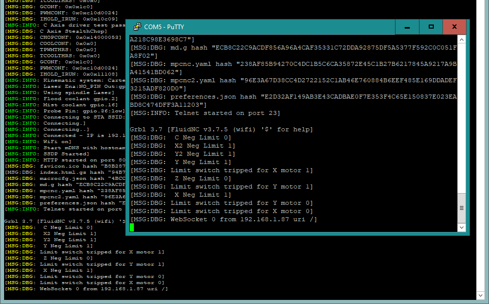
Also I can type commands on COM5 and it responds like the console should.
There is no reason this shouldn’t work, except for all the unknown unknowns (for me). Maybe a small victory but I’ll take it!
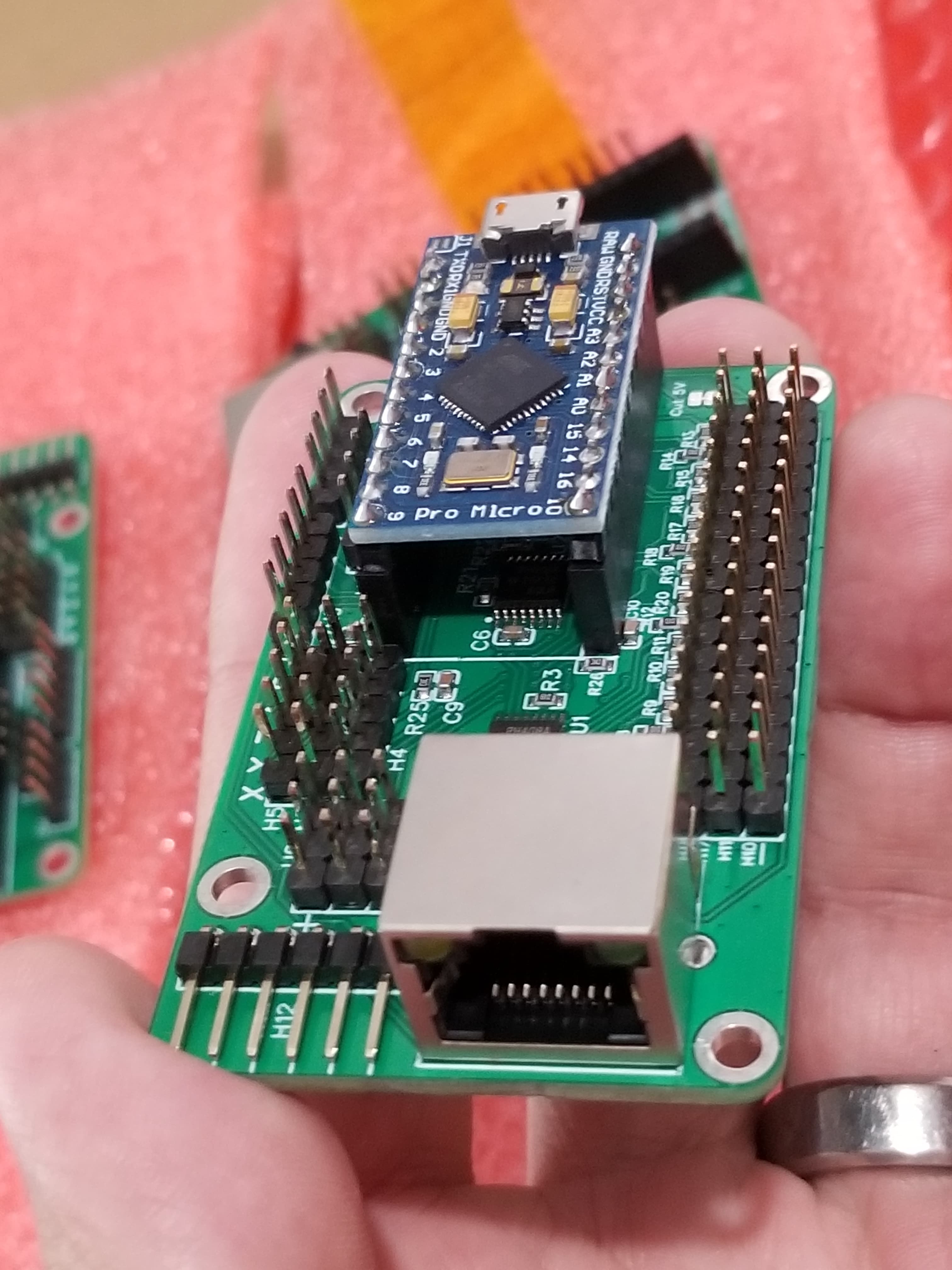
This should answer @SupraGuy 's question. My board is translating 3.3v from the ESP32 to 5V logic.
I can’t figure out if the TFT35 is expecting 5V or 3.3V over the RX and TX lines. Maybe it is 5V tolerant and sends back 3.3V, in which case a little pigtail would be all that’s needed hardware-wise to connect the TFT into the expansion port. The bigger problem is that the TFT firmware is not going to speak the right flavor of gcode so there will be a fair bit of software work to get the screen to work with FluidNC.