- Do you need a long cable? Even on the LR the controller is only on one end of the gantry. The bit won’t be far away.
- Just trying to think of other alternatives. What about a 3.5mm jack? They are common, and abused for all sorts of projects like split keyboards. The DB9 is pretty bulky and the cables themselves are not very flexible. A 3.5mm cable might also just give way if someone trips on it. 2m or so max length would be fine for almost all cases, I think. The baud rate is not high on the UART either.
- The jog uart language is key. If you can use actual jog commands, then it will be very universal. I am 95% sure the grbl jog commands will be good, and they will “interrupt” movement the moment the user changes their mind.
2 Likes
This is great stuff and super interesting! I‘ve just paused the development of my Pendant because of other priorities but will definitely follow your development!
I‘d start with wires for now to reduce complexity. There are serial-over-esp-now libraries you can use later to substitute your transport layer ‚wire‘ by the wireless ESP-now protocol. All you need to do now is to define an interface to talk to your serial port which you then extend later with ESP-now.
I‘ve tested some of these serial-over-esp-now libraries and can say they work reliably at 1Mbit.
2 Likes
Yeah, then go for it. I like to take the approach of deliberately choosing the simplest/easiest option unless I can think of a concrete reason not to. That seems like a good reason.
I make a habit of adding a resistor in series and a capacitor to ground for every signal that is going in or out of a board. The capacitor should be on the connector side for outputs and on the IC side for inputs. It makes it a bit easier to change components if you end up having signal integrity issues. The single easiest way to solve noise issues is to slow down baud rates and add appropriate filters because typically noise becomes more of a problem at higher frequencies. Typically the resistor is sized with the far side load and cable capacitance in mind. I would start with a 100R resistor in series and a capacitor sized to give a corner frequency of 5-10x the base frequency of the signal. So for a 250kbaud uart, that’s 250kHz square wave, so 2.5MHz as a starting point. I would assume that the cable capacitance of around 10-100pF per meter, so perhaps assume there will be a few hundred pF of extra capacitance on top of what you add on the PCB.
For your case it won’t add production cost because the through-holes will be hand soldered anyway. For higher volumes (1k+), it can get tricky because it means you can’t easily use wave soldering, which is the cheapest/fastest way to do through-hole soldering. Selective soldering (using a solder ‘fountain’ on a per-pin basis) is still possible but needs special care to make sure that there is enough space around each through-hole to solder them without accidentally reflowing/removing surface mounted parts. There are ways around all of that, anyway.
Perhaps take a look at using something like an I2C port expander. It might add a little cost but they tend to be slightly nicer parts to work with. Some have on-board selectable pull ups, they often have better drive current and are nice in that they can used like extra configurable IO, rather than just inputs. We use some TI ones that are auto-rated, TCA6408 I think, but there should also be some cheaper ones in the $1-2 each range.
Yeah, that sounds fair. You can also add warnings/directions on the silkscreen which goes a long way in situations like that.
That’s always a trap. I always add them as parts to the schematic early so that I don’t forget them. It’s really frustrating to get a layout completed and then find that you’ve forgotten the mounting holes and have to move everything. Another thing that I like doing is rounding the corners on the PCB to make them nicer to handle, normally just 2mm radius or so. Not remotely necessary, but it’s a nice touch.
I like the idea of the 3.5mm socket with a TRRS connection. As just TRS, that’s a bit awkward unless you’re doing unidirectional comms or something half duplex which could get a bit ugly. The DB9 is definitely bulky but the flexibility depends a lot on the specific cable, there are plenty of thin/flexible ones you can get. We have a few downstairs that would be similarly flexible to an audio cable. There are also a lot of very crappy audio cables that don’t last long in environments with flexing due to extremely fine and low coverage braided screens. The cables being used for keyboards aren’t typically audio cables and are often custom, from what I’ve seen. A proper catenary/flex rated cable would obvious be a pretty cool thing to upgrade to.
4 Likes
I love the idea of the i2c port expander. I’m definitely doing that. Thanks for the suggestion.
I’ll give the passive RC a shot. Sounds like a good idea, we’ll see if I can do that correctly.
I’m second guessing myself on the DB9 now. I’m on the fence. We’ll see where I end up. Adapters are always possible so I’m thinking the easiest/best case for long term is better than over-emphasizing my specific use case. At the moment I’m leaning toward plain 5V TTL over RJ45/ethernet, with a header on each end that would allow plugging a store-bought USB FTDI module. I haven’t thought through the possible combinations of +5V supplies fighting each other so maybe more jumpers.
More to come…
3 Likes
Like any form of development, it’s easy to get caught up in the details. If you’re 50/50 on 2 options, that means it probably isn’t a clear issue which also means that there’s relatively little harm in just firing off in one direction. If you’re worried about the bulkiness, perhaps grab a cable and mock it up, get a feel for it. If it’s too bulky, you can always move to something like the TRRS that @Jeffeb3 suggested. It can still go to a DB9 on the other end for direct connection to a USB-serial if you’re on line level or those FTDI USB-TTL serial units work great. We use those a lot at work. At home, I have a few Bus Pirates laying around that are also super useful for stuff like that.
I’m personally fond of the 5V TTL serial over ethernet cabling. It can easily go shielded/unshielded, if you want much longer distances or multi-drop then going to 485/422 is easier, you can get cabling that is anything from spare in the junk drawer to cheap to epic catenary rated, solvent proof, armoured, direct burial, etc.
To start with, the jumpers are an easy and somewhat bombproof solution. If you put 0R resistors that are marked as Do Not Fit (I assume EasyEDA can do that) across them, it’s easy enough to get a bunch made in a specific configuration, too, without changing the layout.
From looking at the schematic above, I’d make sure to add a 100nF cap at each power terminal, including the headers. Looks like they’re needed on CN1, U7 and the headers.
1 Like
Ok, next cycle, trying to use all your tips.
The digital signals from the port expander have 100k pullup resistors, so a button or switch or an LED (cathode) with a series resistor can be used.

The 6-pin FTDI header is on a right-angle header so I am much less likely to plug it in backwards. There is a jumper on the 5V pin but it still can’t coexist with the ethernet cable because they would try to talk over each other. Removing the jumper allows FTDI header simultaneous with USB directly plugged into Arduino, and with jumper in place it allows FTDI header to power the Arduino when USB is not plugged into the Arduino. Maybe this is not worth the complexity and standalone mode should always require USB Arduino power and never use FTDI power. So I’ll probably remove the jumper and 5V from the FTDI never goes anywhere.
I have SPI available on the Arduino Pro Micro but I can’t think of anything else I might use it for at the moment. I’m a little bit tempted to expose it with a header, but I am also afraid of “just in case” getting out of control.
The other possibility is I could rearrange pins to make PWM pins available, which could be used for analog output, if there were some reason to want that.
The other direction is I could add a second TCA6408 to allow more buttons. If I were to try for some of Steve’s functions and a couple indicator LEDs the 8 pins would run out really fast. I’m thinking I’ll probably add the second TCA6408, and for that matter the 3 extra Arduino pins can be buttons/LEDs too. That would be 19. That’s barely enough for Steve’s pendant, depending how you count.
2 Likes
Looking good, I’m liking the cleaner looking schematics, for sure. I personally like to keep the decoupling caps near the parts they’re intended for, but with their own power ports so make the layout a little cleaner. I’ll try find an example to post up. I was looking for one earlier but most of my more complex stuff would be frowned on if I shared it.
I’d also avoid the 4 way junction like you have for the ground on CN1. I try to avoid these wherever possible because it’s hard to tell if that connection is intended or whether it was accidentally put there when a component got dragged etc.
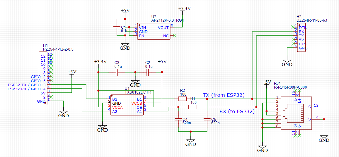
I’m guessing CN1 is the ESP32 board? You’ve got RX labeled on the pendant board as ‘from ESP32’, so that’s ESP32 outputting the serial data stream? But then you’ve got the same thing labelled as Tx ‘from ESP32’ at the other end. It’s a little confusing what that actually means. I guess this is a little bit of a strange situation, but I typically try to label things such that they make sense for the device that they’re on, so Tx would always be a the label for a signal connected to an output on that board, while Rx would always be connected to an input. So in this case, if pin 1 on the ESP32 is an output that is transmitting data, I would label it as Tx on that board and then Rx on the board that is receiving that data. Hopefully that makes sense.
If that’s the case, then the RC pairs are around the wrong way. The easiest way to remember this as a shorthand is that you don’t want to put a capacitor directly on an output, because then it has to drive a lot of current whenever it changes state. The resistor limits that current, which means that the voltage on the capacitor rises more slowly. So the signal goes through the resistor to the capacitor and then onwards.
For that RC filter, one trick is that it’s easy to get a wide variety of resistors but usually harder to get anywhere near that variety of capacitors. I try to design with only 100pF, 1nF, 10nF, 100nF, 10uF wherever possible, and honestly that’s normally 1nF, 100nF, 10uF only anyway. That 100R/620p filter is a 2.5Mhz corner frequency, which is plenty of bandwidth for a 250kbaud signal. You can make pretty much the same filter with 68R/1nF and it’ll be less annoying to build, or honestly I’d usually just pick the closest set of values and do 100R/1nF and call it a day at 1.6Mhz.
Oddly enough, I’ve used those exact level translators before and I’m not really a fan of them. They’re great because they’re automatic and bi-directional, but they tend to be remarkably picky about noise immunity because of how they’re constructed internally. Basically they sit with their IO pins at high impedance and wait for one to change state. When it does, they briefly go low-impedance at the new state and then go back to high impedance. As a result, if you do have a brief noise spike or something else that gets into them, they are very hard to keep from changing state and basically amplifying that noise. We stripped them out of a design for that exact reason. I would always rather use a uni-directional one like the TXU0202 series that we replaced them with. These translators aren’t cheap compared to some of the other options, but they are quite robust and they’re also available with different configurations. The TXU0102 is 2 channels going the same direction, the TXU0202 is 2 channels going in different directions.
However, looking at it, I don’t think you’ll actually need it if CN1 is an ESP32? The ESP32 devkit style boards take 5V in, but the microcontroller itself is 3.3V, so any logic outputs will be 3.3V. The pins are 5V tolerant, but it’s generally better to use 3.3V when interfacing with them because even if a 3.3V input is 5V tolerant, a 5V input may not reliably be triggered high by a 3.3V signal.
On the pendant board, what is VCC and what is generating it? You’ve got 5V coming up the cable, what looks like a 5V to 3.3V regulator and then VCC. If VCC is the on-board power supply for the ESP32 then it’s 3.3V being generated by its own regulator. I’d have to check the pinout of the ESP32 board you’re using because there are a few that are all similar (which is a trap I’ve fallen into embarrassingly often) to know for sure.
That’s a new strategy to me, can you explain how that helps with the orientation? I generally think that the best thing you can do to avoid plugging it in backwards is have a nice clear marker for pin1. I usually just use a larger white dot/arc. If it’s not clear on the FTDI cable, putting a mark with white tape or a dab of paint makes it super easy.
That’s good to be considering all of that, for sure. If only the FTDI header or the 8P8C header can be used at once, it might be worth just making it so that the power supply is just one or the other. You can do that by using a 3-pin header, having pin 1 be the 8P8C 5V line, pin 2 being the +5V on the board and pin 3 being the FTDI +5V.
Yeah, I know the feeling. I often take the approach that adding stuff to a PCB layout doesn’t really cost anything other than board space. It’s a little different if you’re getting boards assembled, but I’ll often put headers on that go to spare pins or ports. On a design I’m doing at work right now there’s an I2C header that wasn’t used for anything, but we’re going to add some extra sensors to it. Having the header there means I can evaluate those sensors separately if they show up before we finish the board re-spin. If you don’t want the space of an entire header, it’s quite easy to solder wires directly to through-hole connections, so sneaking a temporary or development SPI connection onto this board isn’t that hard to do. For connecting to spare SMT pins I’ll usually add a test point (something like a Keystone 5001 if I have space, or just a 1mm diameter round pad if not) for each, which at least makes it easier to connect to later. Perhaps think about it in terms of cost/benefit? If it’s a 10 minute job to add and doesn’t cost anything then it’ll probably save 10 minutes of stuffing around in future if you want to add something like a character display or whatever. If it was an hour and $5 of cost but you only had a 5% chance of using it for something, that seems like a bad deal, perhaps? I don’t know, that’s the tough one. Feature creep is a real killer, for sure.
I very rarely come across situations that I need analog outputs via PWM, but it can be worthwhile making sure that at least some of any external drive is capable of PWM. Even if just because it can be a lightweight way of generating a clock signal or controlling an RGB LED or whatever.
If you’re worried about potentially wanting more buttons, perhaps you could add another I2C port expander and make the addresses settable via resistors (just put 0R resistors to both GND and +V on both address lines and specify that only one gets fitted) or a DIP switch? If the I2C port had power and ground on it, potentially you can just plug another identical board to that one via the I2C headers but with the ESP32 disconnected and then you’ve got a 2nd bank of port expander IO?
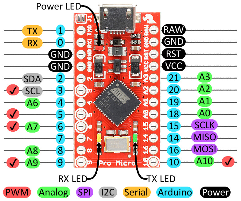
The board going in the socket on the pendant is the Arduino Pro Micro. I’ve been using this sparkfun diagram for the pin reference:
The ESP32 refers to the controller on Bart Dring’s 6-pack controller or Ryan’s Jackpot board. I’m never sure how to label TX and RX since they change meaning from context but it sounds like my choice is similar to yours. Pin 1 on the ethernet is transmitting from host (ESP32) and received by device (Arduino) while pin 3 is transmitting from device and received by host. From googling, it looked like this was the standard assignment of wires in an Ethernet cable, so it seemed like a natural choice.
The Arduino Pro Micro comes in both 5V and 3.3V flavors, and I happen to own two that are 5V. The 3.3V one would probably work equally well and can be powered by 5V while VCC is 3.3V in that case. My encoder wheel from Amazon indicates 5V operation but it might work at 3.3V, or maybe just give it 5V supply and put voltage dividers on the outputs and call it a day.
Arduinos are “traditionally” 5V and I could imagine that expecting 3.3V could be a source of mistakes. If I were to keep with 5V Arduino, the TXU0202 looks like just what I would need, but it’s apparently not stocked by LCSC so it would blow the assembly. I’m not finding equivalents, and the nearest I can find is to get two 74LVC1T45. Since they’re uni-directional I would hope they are simple buffers.
The Arduino gets 5V from the USB port and makes it available on the “Raw” pin (I am calling +5), or you can supply power on that pin and leave USB disconnected. Then on the board it has a regulator that produces VCC that will be 5V or a bit less than the input voltage. The ADCs will be referenced to VCC and not to “+5V” necessarily and pullup resistors for example need to be VCC and +5V might be too high.
It so happens that using a 3.3V Arduino with VCC = 3.3V should just work I think, since everything that matters is referenced off of VCC. The exception is the encoder wheel which should probably take +5V as supply instead of VCC.
The OLED (SSD1306 intended for header H2) is a bit weird. It tolerates 5V on the I2C lines but it does not tolerate 5V on the supply. I found out the hard way (didn’t cook anything, but produced weird behavior).
My FTDI board has one side that’s obviously “up” so that keeps the orientation correct, assuming the board/pendant has an obvious “up” orientation.
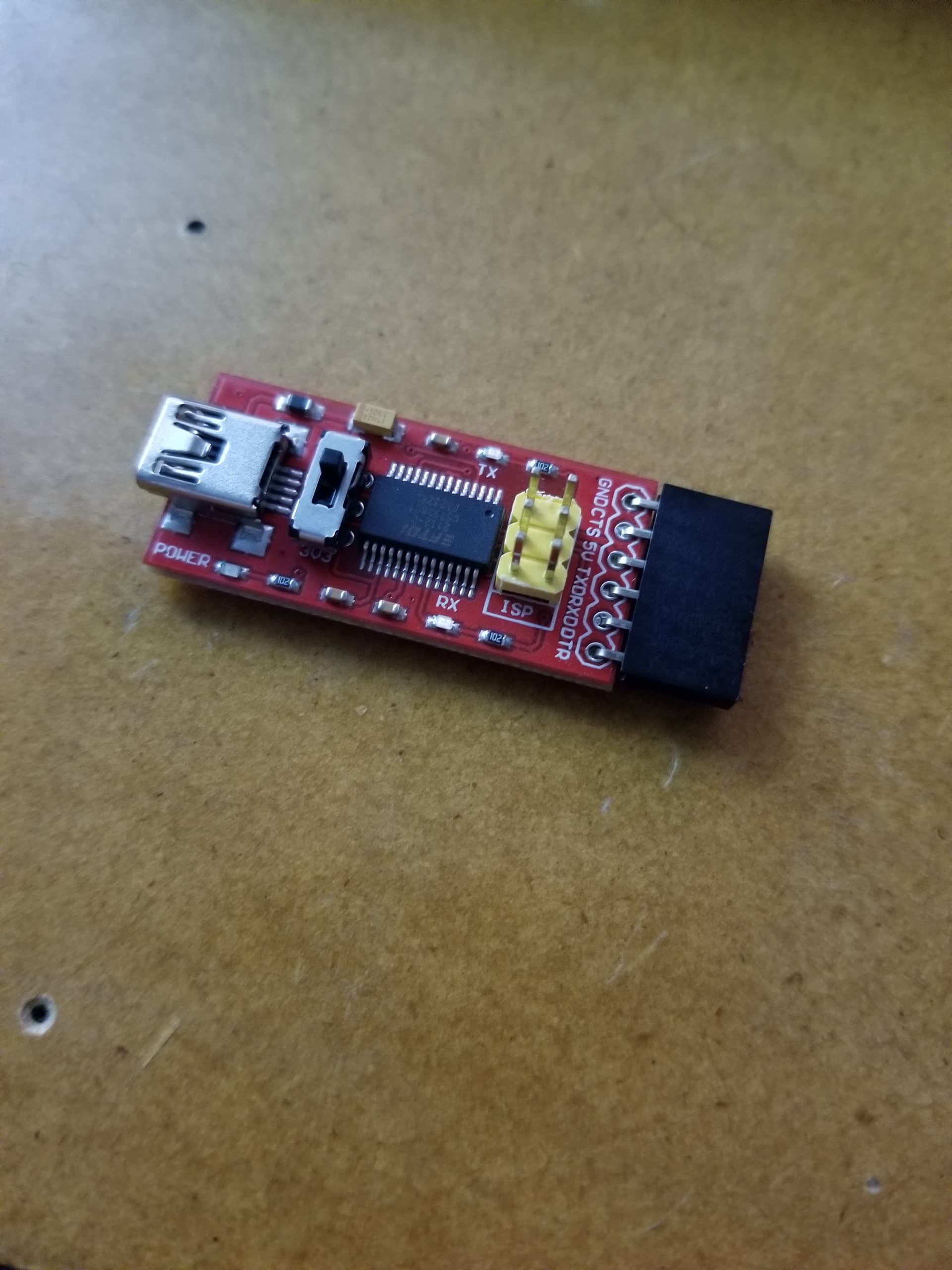
In my goofing around with a breadboard the last few days it is vertical and I’ve already plugged it in backwards once.
I had another thought for the power jumper but it’s a bit too crazy. For now suffice to say the FTDI supply is useless since the only times I would use it (debugging) I would also have usb power handy.
You’ve definitely given me a lot to think about.
Even though there are a lot of changes still happening or under consideration, I feel like this is converging, and improving, so it’s definitely progress, not just indecision.
Ah, that makes way more sense. Yeah, I follow now.
If the encoder says 5V operation then I’d probably stick to using that. I’m not a fan of using components outside their ratings. Too many possibilities for wasting time due to unexpected behaviour! Voltage dividing from the output to a 3.3V micro is how we’d normally do it. If you put a capacitor on the low side of the divider then you’ve got a filter and you’re away, the key thing is just to make sure that the resistor values of the divider are not too low so it draws too much current constantly or too high so that you get too much filtering and slow edge rates from the input pin capacitance. I normally use a 4.7k as the ‘top’ resistor and a 10k as the ‘bottom’ resistor for that.
Figuring out where to do the split with a design like that can be pretty difficult. I typically try to keep as much stuff on the supply voltage as possible. I’m typically designing for 12/24V input and then using something like a VX7805 buck converter to create a 5V rail, then a linear regulator to create a 3.3V rail. If I can, I’ll try to keep most things on the 5V rail because it usually ends up being the nicest combination of easy to implement and efficient. Extra load on the 3.3V rail inherits a 30% drop in efficiency from the linear reg and makes keeping the regulator cool harder. In other cases, it may be more obvious because going from 5V to 3.3V can be easy providing you don’t want too much speed, going from 3.3V to 5V is more annoying. Choosing to split wherever provides the fewest voltage level translations is probably a decent compromise, most times.
Yeah, the issue with a lot of modern and easier to design with parts is that they’re hard-core single source so if you can’t get hold of it then you’re screwed. With a general purpose gate then usually there are dozens of companies making them. I think I’ve used that gate in the past as well. There can be some tricks with making sure that input and output thresholds match with mixing TTL and CMOS logic, but in general it just works well enough to not worry too much.
Oh, that’s quite different to the ones I’ve used before from FTDI. Ours are just cables where the entire driver is in a moulded enclosure and a series of line sockets are used to connect to the board. Yeah, that looks like a good fit, then.
That’s how it would normally be handled. Everything is referenced to the same rail and that rail can be pretty much whatever you want, but by convention it’ll be one of several common voltages like 5V or 3.3V.
Yeah, that’s quite common. Typically that will be called ‘5V tolerant IO’ or similar. ESP32s are the same way, they handle 5V on the IO but need a 3.3V rail. I’m generally not as much of a fan of 5V tolerant IO because it can actually be less robust in certain situations due to the lack of bypass diodes to Vcc, but it sure can make life easier in the right circumstances. I2C is a great example of that because its active-low, passive-high nature can provide that automatic level translation.
Yeah, for sure.
1 Like
You should just use CANBUS
I’ll see myself out.
5 Likes
Don’t go just yet, are you (or someone else here?) familiar with using CAN instead of I2C. If you reasonably understand I2C already, how much more involved/harder is it to learn, design and code to get CANBus working reliably?
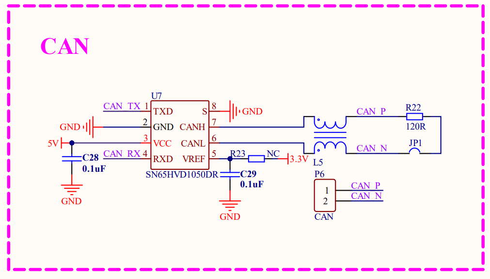
Looks like Texas-Instruments-SN65HVD1050DR is stocked by LCSC and just $0.68, Datasheet PDF
Can see example usage in BigTreeTech EBB36 > Schematic. Klipper and CanBoot firmware are open sourced of course.
Had the opportunity to briefly learn some aspects of CANBus when assembling my MP3DP v4, ran into some issues, that required troubleshooting CANBus.
3 Likes
![]()
![]()
![]()
1 Like
Oh boy, CAN is an interesting one. It can simultaneously be super easy and incredibly complex. With so many devices having CAN controller hardware on board now, it’s a lot more straightforward than it was.
On the hardware side, CAN is a bit more heavyweight in terms of needing a transceiver for each node, a balanced line and terminations in the ‘typical’ implementation, but you can also use it in a very similar way to I2C within the same board by omitting the transceivers entirely and just using it at logic level.
The great thing about CAN is also what makes it a little weird to get started with. There isn’t really the whole ‘controller/device’ paradigm, nor is it strongly limited to ‘sender/recipient’. It’s inherently multi-drop and automatically arbitrated. It’s just controllers firing frames out onto the bus and as long as something out there ack’s the frame, everything is fine. All devices can see all frames and any device can send a frame at any time. This is great for situations where you might have multiple controllers all wanting access to the same information, or where you may not be sure how many controllers will ever actually be on a given bus, etc.
An I2C interface typically has a controller that will do all the clocking and devices that will respond with data. Great for stuff like a micro connecting to a bunch of sensors in a lightweight way. Somewhat irritating to use to try to connect a pair of micros etc. There’s a much, much larger ecosystem of end-point devices that support it, as well.
It’s quite a different approach, communication wise. Standard CAN works by defining addresses that always contain the same data which works great for moving sensor data around or updating controller set points but can get kinda weird when you’re using it to control something stateful at the far end. There’s really nothing that cleanly maps to the concept of ‘sending a command’, so in the past I’ve ended up doing a lot of complex passing flags back and forth to avoid race conditions and such.
Another thing is that most CAN controllers give you all of the tools you need to thoroughly hang yourself through the ability to control things like the timing behind when a bit it sampled and how much oversampling occurs.
There’s also no standard definition of how data should be ordered within a CAN frame. It’s just 8 bytes of ‘whatever’. This can often include single bit flags, 8 bit values that may not be aligned to a given byte in the frame, 16, 32 and even 64 bit values that can be either big or little endian as well as having any byte order you can come up with.
There’s CANOpen which implements a layer on top of standard CAN and can work much more like a standard data link with frames of ‘whatever’, but that’s a hell of a jump in complexity again.
For something simple where you can get it all done within a few frames and keep the definitions of everything centrally managed then I think you could probably just define it all by hand. For anything slightly more complex, you’d typically use some 3rd party software to define the system in terms of which buses have which settings, which frames will appear on which buses, what information each frame contains and what form that information is in terms of scale/offset to real world values, what the acceptable range is, etc. We’ve used Vector and Peak Systems software tools for that in the past and currently use PCAN Developer, which I think is in the $3-4k range. I can’t remember what our Vector package set cost, but it was well into the tens of thousands range.
2 Likes
Just realized I probably didn’t actually answer your question.
In terms of how hard is it to get CAN working? At a basic level I’d say not ‘that’ much harder, but it’s much more open so it depends on what you’re trying to do with it.
I2C, chances are you’re hooking up signals from to the microcontroller to a device and using a library on the microcontroller that handles the hardware setup and control, which is normally just pin definitions and clock rate. From there, it’s looking at the documentation on the device, figuring out the address and then calling functions that will read/write the appropriate data to that address. Pretty easy, not a whole lot to go wrong.
Fundamentally, CAN won’t be that different. You’re hooking up signals from the microcontroller to a CAN transceiver and likely out onto a wire, then connecting that wire to other CAN devices. You’ll still use a library that sets up the CAN hardware for you. From there it gets a little trickier, in my experience. The hardware operates much more ‘in the background’, so instead of requesting data, you’re waiting for new messages to arrive or firing an interrupt when they do. There are also a lot more configuration options in terms of bit timing, potentially needing to define which address masks are being listened for, potentially setting up multiple different mailboxes to listen for specific messages. Some of this may be specific to the hardware I’ve used and may not be the ‘common’ generic implementation, I’m not sure. You also may need to define things like which messages will get acked etc.
If you’re using a pre-existing CAN device then it probably spits out frames at a specific rate and with pre-defined addresses. Reading data from those should be pretty straight forward. You’d define a CAN message that would be sent out (address, data loadout to match what was documented, send via a function) or define a message ID to listen for and then an interrupt handler (or wait loop) to act on that incoming frame, unpack it and do something with the received info.
If you’re using it in a situation where you’re talking between 2 devices, it’s much the same as above but you need to go through and define the message structure itself. At the simplest level this is easy, but it can get complex. Ideally you’d pay attention to which addresses you’re using, because lower numbered addresses have higher priority and will ‘win’ arbitration processes more often. You’d define frame repetition rates so that low update rate data might be 1 or 10Hz while fast update rate data might be up to 100Hz or beyond. You’d be checking that to make sure that you’re not overloading the bus and blocking the lower priority frames from transmitting, as well as having defined timeouts after which you flag an error due to a loss of communications to the other device. You’d need to make sure that both ends are using the same endianness and byte order, otherwise things can get real weird.
One nice thing about CAN is that due to it being a somewhat ‘higher level’ interface than I2C, there are a lot of options for mucking about with it. It’s relatively straightforward to use a PC with a USB-CAN interface to pretend to be a sensor or controller, for instance. We will often set up a project in PCAN Developer which pretends to be a device that we’re connecting to. That way instead of needing to test on an actual vehicle where we might not be able to make the battery management system do everything we want, instead we can end up with a slightly janky interface full of buttons and sliders that lets us set any values to anything we want. That way it’s a lot easier to test the firmware interfaces and that things like protection modes work, response times are good enough, error handling makes sense, etc.
So yeah, I’m still not sure I actually answered that question. I guess I’d say definitely more complex, but also some of that is just because you have a LOT more freedom with CAN, which brings with it its own complexity.
2 Likes
CAN sends 8 bytes in each message. That makes it tricky for gcode. Some commands, like G1 X100 are less than 8. But G1 X12.1234 Y1.234 F376.458 are not
I think that also makes the I2C overly complicated. Whatever you make would be more generally useful if the grbl/marlin side was just 5V(3.3V tolerant, ideally) uart at 112500 or 250000 baud. Any higher voltages or different protocol means you either have to have a special kind of grbl or you need a translator chip in between.
Having a translator that collected multiple CAN messages into a stream of gcode would work. But it is more conplicated and adds more parts. The big benefit is noise rejection. But I would wait to see a problem before I tried to fix it.
Appreciate all the CAN info, learning lots, cheers!
Sounds like CAN is better suited for sending sensor on/off/position/orientation/other information easy to represent in small payloads. Maybe GCODE generation happens within an MCU on the IO port Expander, or the JackPot ESP32 even (providing additional Pendant specific interrupts/compute won’t impact/destabilize JackPot ESP32’s core CNC/whatever processing)?
Stepping back from CAN, and up above protocols for a bit… Sounded like Jamie’s going with UART/Serial for MVP? Curious what required features and functions the Pendant must/should have? Just multi-axis-joysticks, knobs, dials and button sensors, or will there be a read/touch display, any other ways for the User and/or Software to interact with the main Controller?
Where will mapping of sensor state to gcode generation happen? Within FluidNC similar to Marlin’s Joystick implementation, or will Pendant’s MCU, and/or MCU on the IO expander… generate gcode from the sensor state?
Guessing User won’t be explicitly entering GCode for a v1 MVP, they’d probably be better off using a wifi tablet+keyboard setup with FluidNC’s existing webui in that case.
CAN is specifically designed around frequently updated individual values. So in this case it would be typically be used for things like the joystick positions, not direct machine control. You wouldn’t send gcode over it because that’s something that has been entirely devised around a serial stream. Instead, you’d do something like define a frame that was a movement command and then do something like X position, Y position, Z position, all as 16 bit values and then a command value. Or if you needed more precision, have multiple frames to set the next position/feed rate and then another frame that updated a flag to ‘execute’ the move. That’s what I mean with CAN requiring a different kinda thought process that makes it a bit tricky.
On the other hand, if you just want to communicate a bunch of info about a system in a straightforward manner, it’s great for that. A frame could have a 100Hz update rate with current position, temperatures, IO status, all sorts and you’d just watch those frames come in and update local variables as required, no issues. With some more complex hardware blocks on fancier microcontrollers, you can basically just treat it almost like a long-distance DMA setup.
@azab2c I think the existence of web UIs is probably a good way to keep a lid on some of the complexity and feature creep. At some point, there will be functions that are probably more suited to a menu or touchscreen setup than dedicated buttons on a hardware controller, I’d say.
2 Likes
The current plan is to move all of the sensor detection into an external MCU, and the host, whether FluidNC or Marlin will get information via serial. A custom non-gcode serial connection could be done but I think sending gcode commands (and adding gcode commands where necessary) can accomplish almost everything that can be done with a custom serial, provided there is a facility for queue-jumping immediate processing.
My analog joystick for Marlin could be implemented through g-code if there were a way to:
- Perform relative move without switching between G91 (relative) and G90 (absolute) state and switching back. (Grbl has this with jog commands)
- Query queue depth to control latency by adjusting the rate of issuing commands
That’s basically it for the joystick but for the pendant I’m wanting a lot more functionality.
Buttons and handwheel are pretty self-explanatory as far as what they should do.
I also want instant feedrate adjustment. The use-case for going slow and for going fast are somewhat different, so I was thinking two knobs. One for going slow (0 to 100%) and the other for going fast (1x to maybe 5x). The slow knob would double as pause function, and by turning the knob within maybe 0.5 seconds you can stop and start without losing steps from excessive acceleration. Or if things are going poorly you can reduce the feed rate. The go-fast knob is if you turn out to have chosen a conservative feed rate and you want to see how fast you can go before the router starts making unhappy sounds. You can turn it up and then back off a bit. The slow (0 to 100%) and fast (1x to 5x) knobs are multiplied together so you can still pause and resume if you are going in overdrive.
These are straightforward enough to turn into (new) gcode commands, but the receiving end might be a challenge.
3 Likes
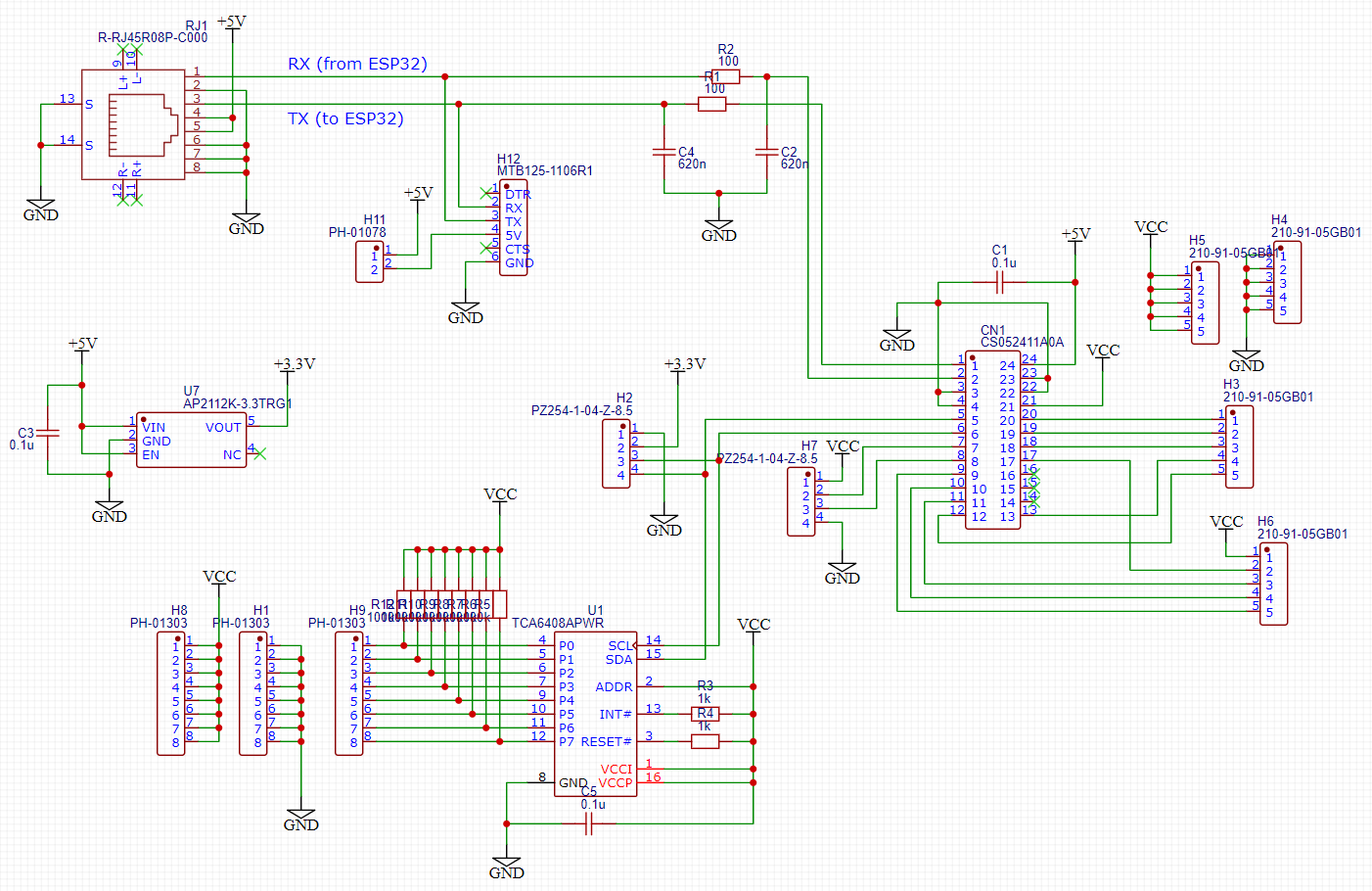
Okay, I think this is getting pretty close to done:
I/O Expander uses two one-bit translator instead of bidirectional.
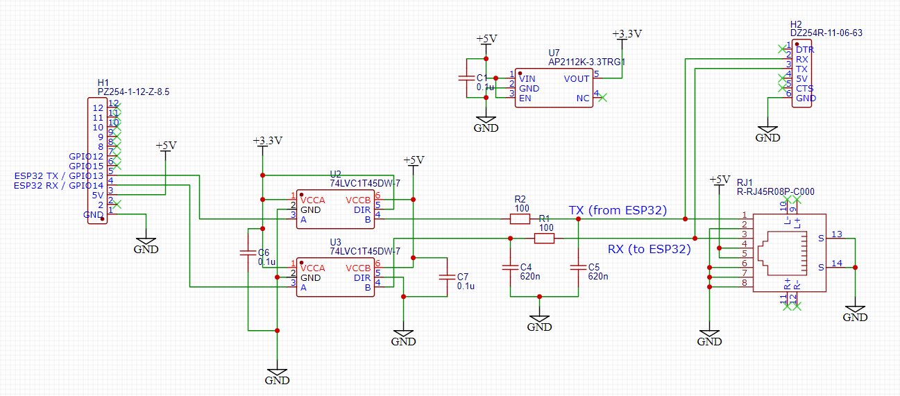
I put only one 100nf cap per supply for both translators instead of one each. I’m thinking that’s okay this time.
The pendant now has two port expanders on the I2C bus, configured with different addresses where the ADDR pin allows two devices on one bus.
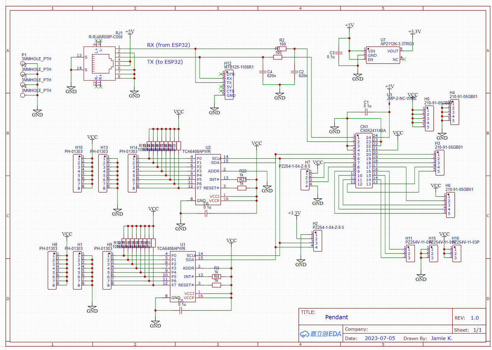
I addition, I mapped the remaining three Arduino pins to three more I/O headers, so they can be used as extra buttons/switches/LEDs, or they would also be available for a future SPI device. So there are 19 pins in total available for buttons or LEDs.
I also dropped the 5V connection from FTDI for simplicity, and I added a NC jumper on the Arduino supply that you can cut if desired. This allows plugging two pendant boards into two computers via USB and connecting them to each other with an ethernet crossover cable, and one computer can generate keyboard/mouse inputs for the other. That’s a separate project someday (maybe never).
I trimmed the I/O Expander board to be a bit shorter but still long enough to be supported by the standoff
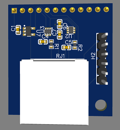
The pendant board is pretty dense but the auto-router found paths on only two layers, so I guess it’s fine. I didn’t forget the mounting holes and I also rounded corners. The overall dimensions are only 67 mm x 40.6 mm.

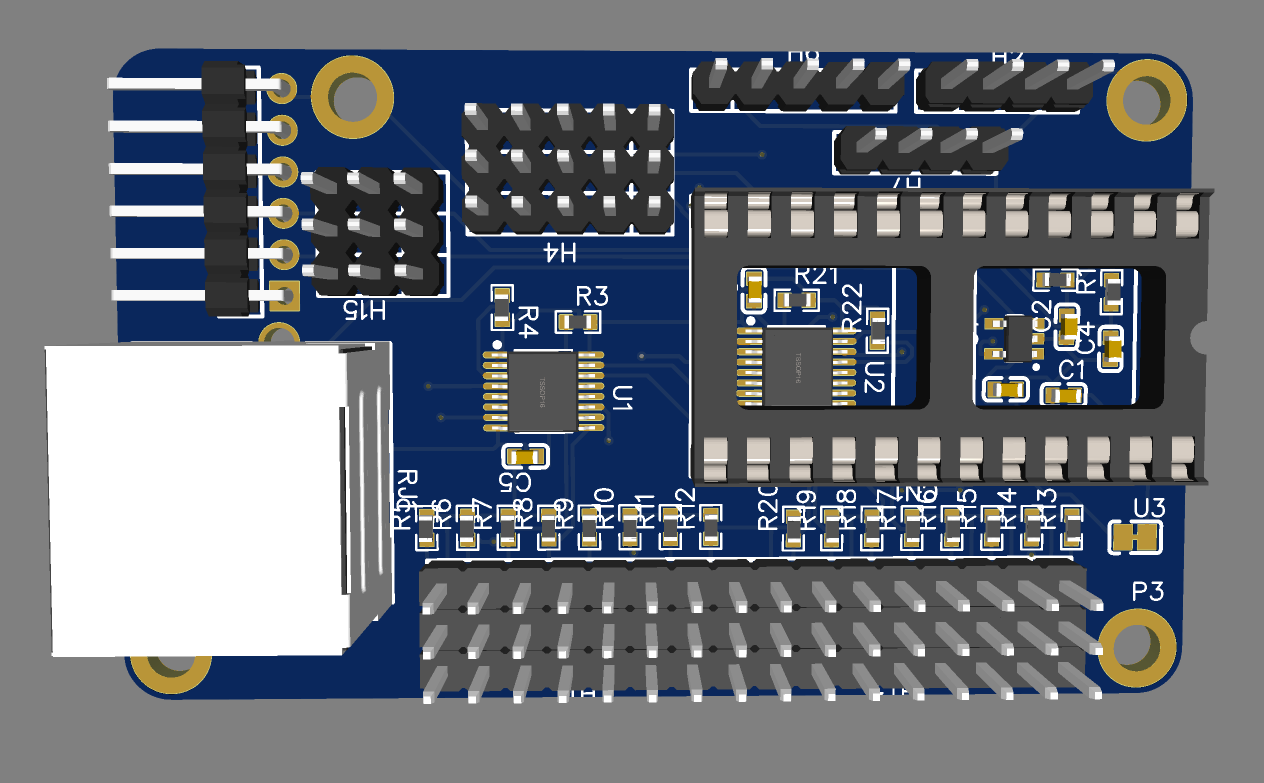
If there are no major errors, I’m ready to order these!
5 Likes