So I found another forum post that seems to explain my issue. I don’t quite understand what is going on but it has something to do with the G54 creating an offset and the machine sometime using that for coordinates. The correct fix seems to be to send a G10 L2 P0 X0 Y0 to reset things back to 0. I also added in Z0 to get everything zeroed out. My G54 was previously [G54:610.000,300.000,-68.185]. I’ve reset things and I’ll see what happens with it when I have more time.
1 Like
I have not read all the previous statements but, you are using workspaces I am not sure if that is your intentions. I never do I skip all that and just use G92 like shown in the instructions. While that is proper machining grammar, I find it overcomplicated unless you are using fixtures.
1 Like
I’m not sure how the workspace got set to what it was. I never intentionally set it, so maybe I did that unknowingly when trying to learn how to use the system. For now I’ve cleared it out and will use it with just G92 at the start of operations.
2 Likes
Ok I took Doug’s previous advice and used a pen to mark 2 points in the y 2200mm apart and 2 points on X at 1100mm apart. I then did the back calculations and was able to get the as close the the intended distance as I could visibly measure with a flat tape measuring tape.
I went and cut a 100x100mm test square to see and I ended up being bang on at 100.00 on the X but the Y was .1mm short. I reran the 2200mm pen dot check and it was still bang on 2200 so I’m not sure I want to adjust the Y micro steps anymore. I’m wondering if the x axis is maybe a little sloppy without the struts and causing it to cut a little more as it moves through the piece. I was using a 0.3mm finishing pass to avoid this. The core is tight enough, but maybe it isn’t totally square vertically.
At this point I think I’ll just cut another strut and see how it measures and if that’s good then just finish the struts and make the finer adjustments once it’s fully built.
2 Likes
All your steps taken sound great. I definitely think it’s a good plan to cut strut and install, then see what that gets you!
This is not unexpected, as tool deflection, backlash, looseness on the gantry, etc,. could account for some variation.
(Edit - I see that you used a finishing pass)
You might try climb milling vs regular milling to see of the dimensions change. One method will deflect the tool into the cut line, and the other will deflect the tool away from the cut line (can’t remember ATM which is which)
1 Like
I’ve gotten 2 struts cut so far and they measure as close to the right dimensions as I can measure with just a tape measure. Seems like it’s just a slight inaccuracy cause by the cut. I am using conventional milling for now. I figured it’s working well enough, don’t change anything and just cut the struts. I’ll reassess after reassembly.
4 Likes
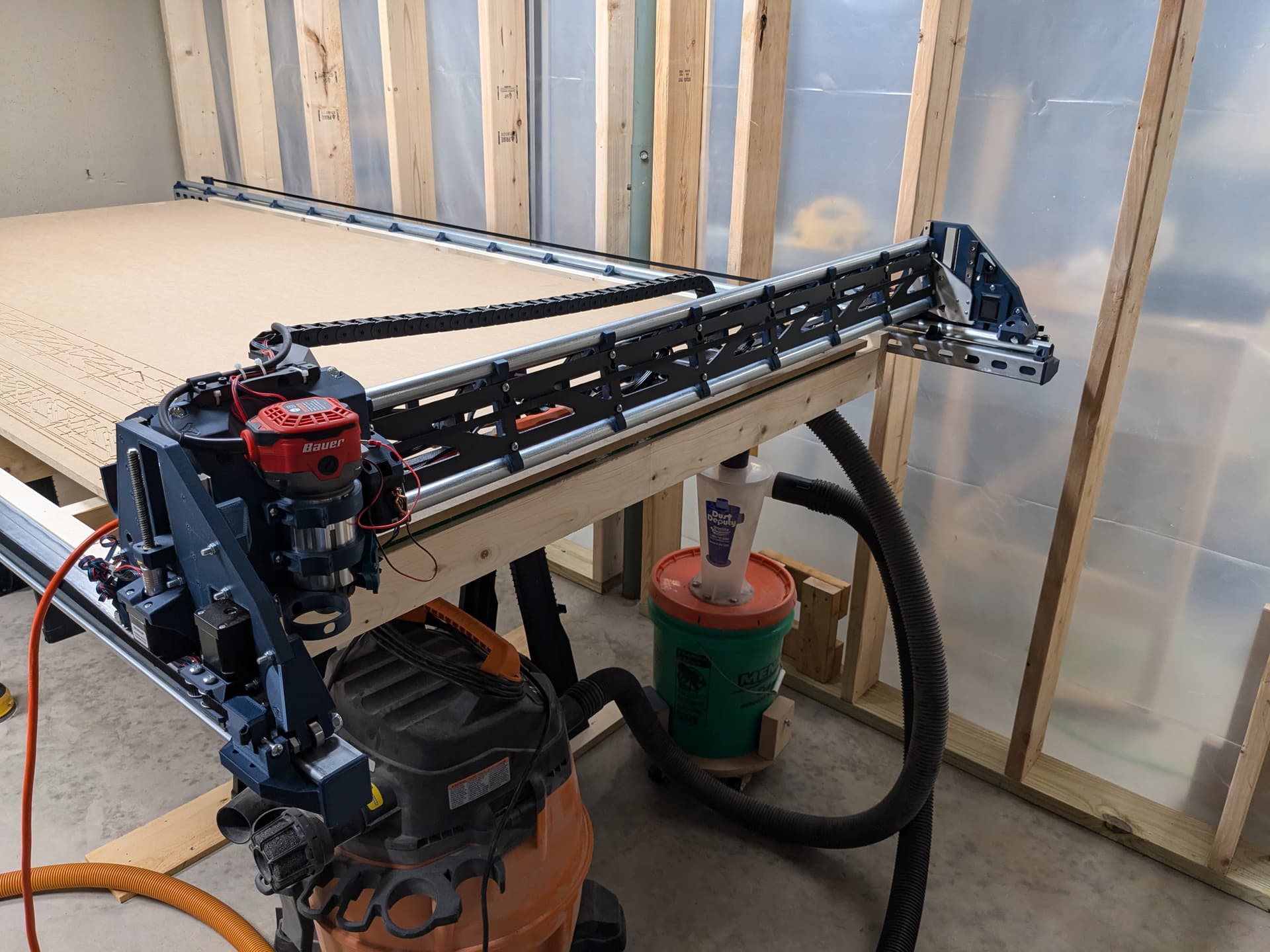
All the strut plates were cut, painted, and installed. I did have some trouble getting the struts on. I had to loosen the whole system to get the holes all aligned with the bolt holes. I tried my best to avoid any twist when putting things on and I think I managed ok.
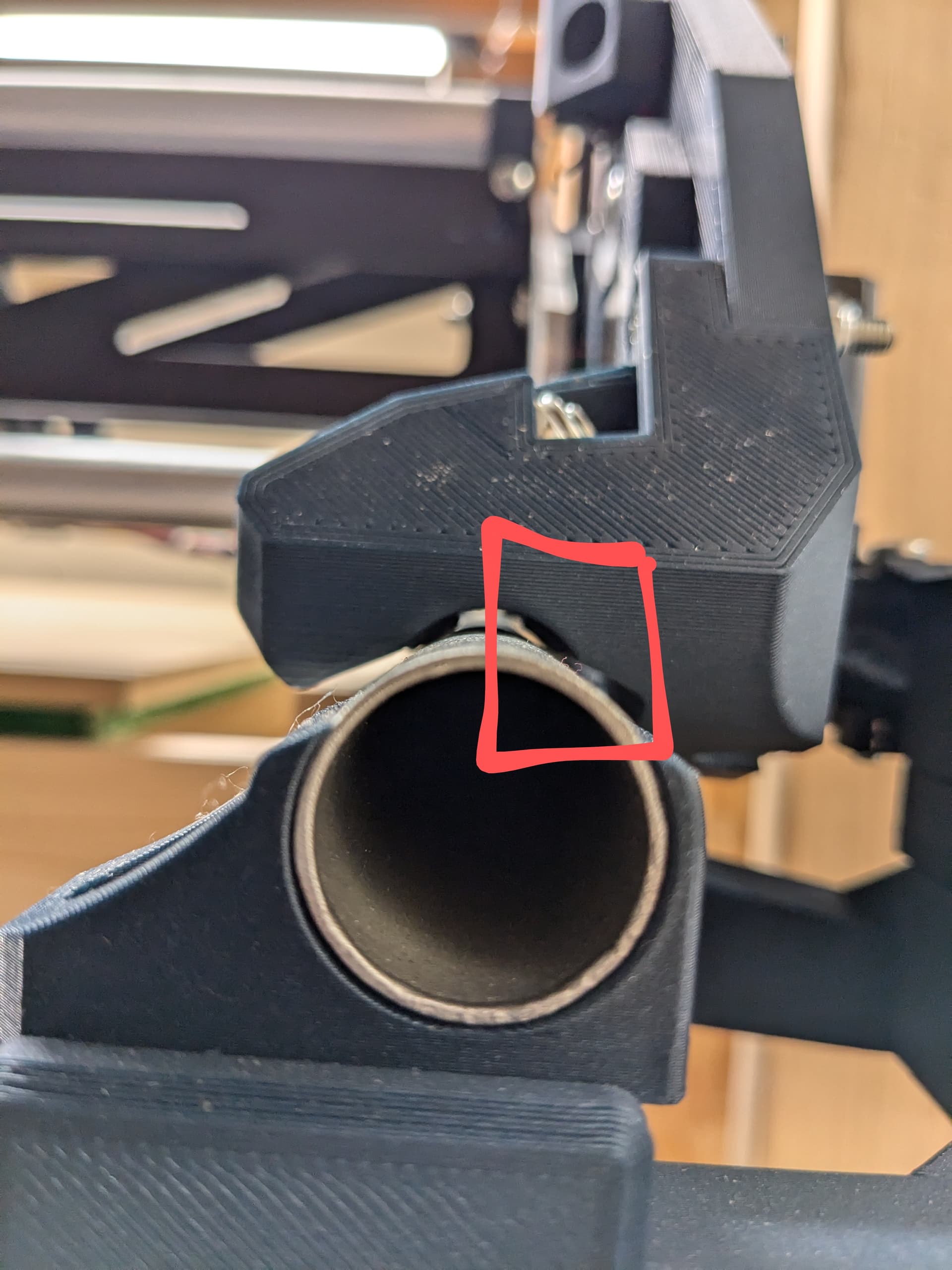
I put the system back on the rails and measured heel/toe distances before putting the y belt tensioners on and everything looked good. Once I put the belts back on and homed everything the rail side was not sitting correctly on the conduit. There is a small gap where one bearing isn’t making contact.
I haven’t done a squareness test yet so I’m hoping that reveals the pull back is a little bit off and then that hopefully fixes it. If not, I suppose I’ll be back here asking about it.
3 Likes
Wow, congrats!