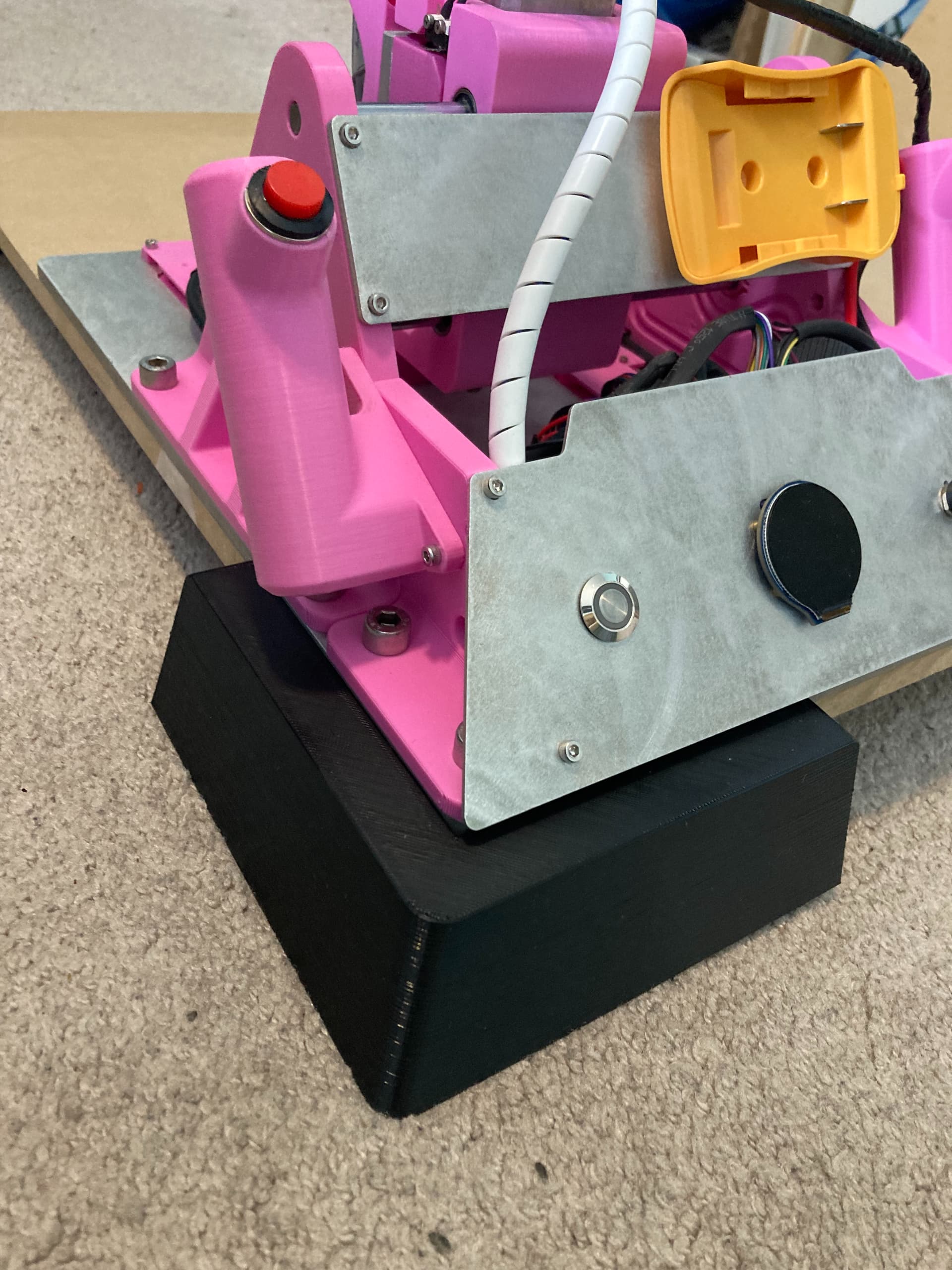
Sharing some progress I’ve been making on the path planning front of the handheld CNC router. Because of the unique nature of this CNC, all of the toolpathing has to be custom made to fit a dynamic workflow where the workpiece is always moving. I’ve chosen to approach this in an interesting way, utilizing the already-so-great-and-powerful CAM software that is already out there to get a generic toolpath, then running the gcode output through my own post processor script to put everything into language that my device will understand. Right now, the only things my post processor is extracting from the gcode are the XYZ coordinates (while ignoring travel speeds, spindle speeds, other gcode commands).
There is another layer of complexity added to this path planning when taking into account the current design of Compass, which only has two axes of correction. This means that the third axis is controlled completely by the user, making complex cuts a little more tough - though not impossible - to perform. The problem boils down to the router being limited to a certain angular range of points in front it. If you imagine wanting to cut a straight vertical line, that is no problem: as the user moves it forward, the motors don’t have to move the tool at all. If you want to cut a line that is tilted, though, the motor has to move faster to keep the tool on track. As you keep tilting that line more and more, the motors reach a point where they can no longer react fast enough. This makes it so that the device essentially has this ~90º FoV in front of it where it can cut:
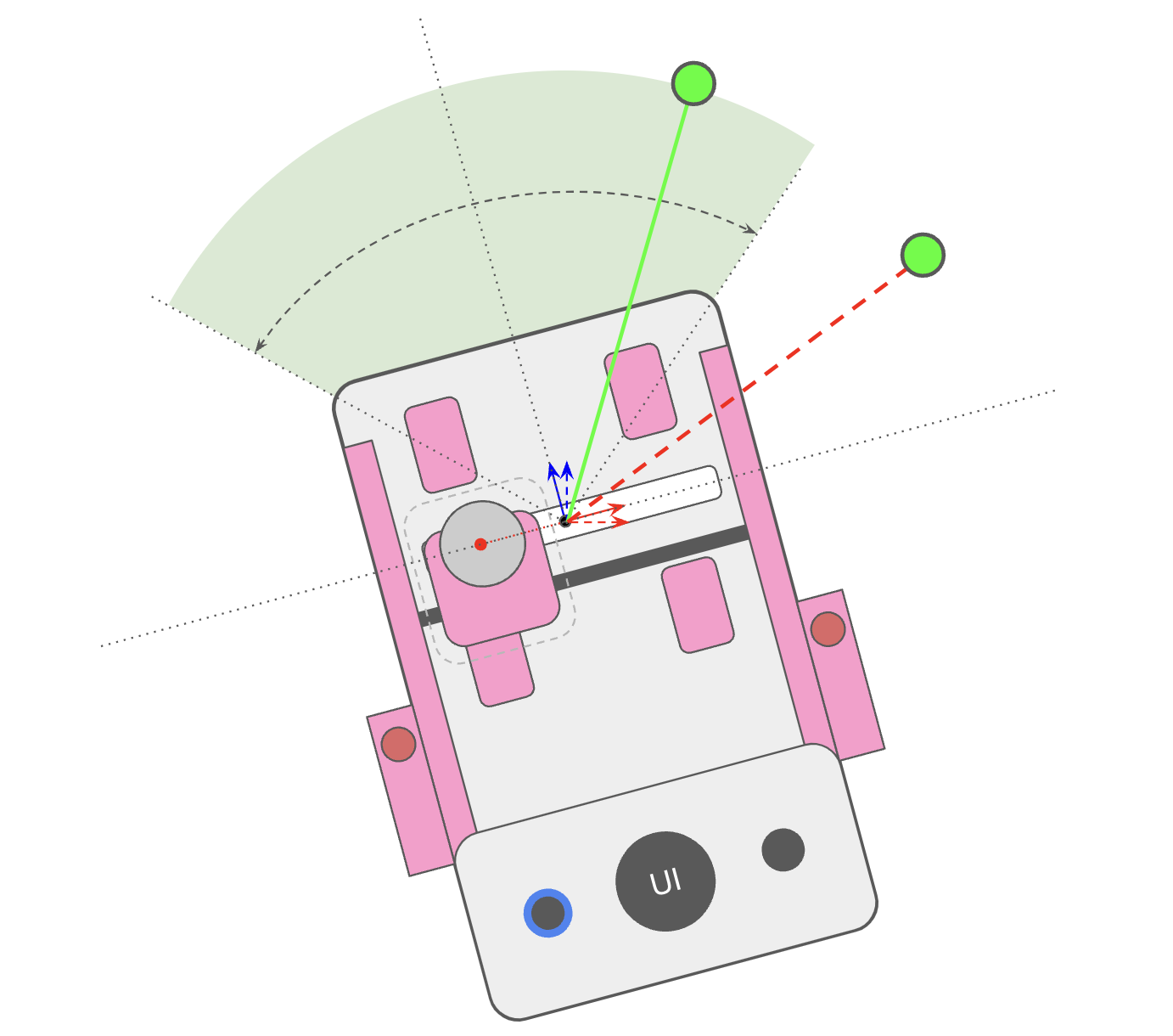
The 90º number is a little arbitrary because it really depends on how fast you’re moving the router, but at a normal operating speed, that is a decent bound. This doesn’t mean that the router is just limited to straight lines, though. When cutting a circle, for example, you could continuously rotate the router as you move, keeping the correction axis perpendicular to the circle’s tangent as you go. You could also cut half of the circle by moving the router forwards and backwards, and then the other half by rotating the device by 90 degrees and moving the router forwards and backwards. This second approach can be generalized much more effectively to any arbitrary design. You can split up any design into a few angular zones that can be cut by the router using multiple back and forth passes.
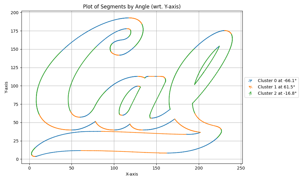
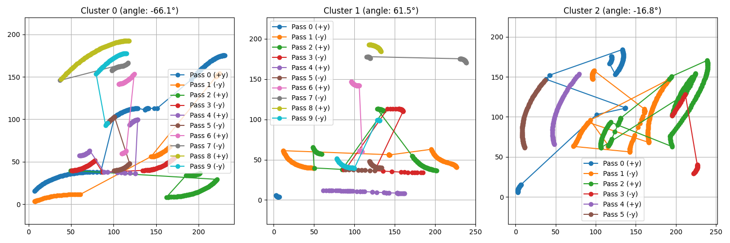
I’m using an iterative k-means approach to group all the lines of a design into the minimum number of clusters possible. While this isn’t 100% perfect, it works pretty well. The next step is to split up each cluster into passes for the router. This is an example of what that might look like for cluster 2:
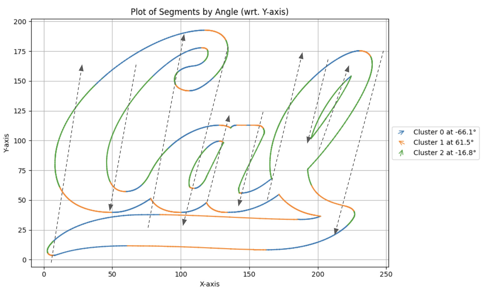
The tough part for me right now is automating that in software. I’m getting a bit of gobbledeygook at the moment:
Almost there though! It’s exciting because once this is done, I can actually start using Compass for actual woodworking projects. Up to now I’ve just been hardcoding the paths, which is hard to do for anything too complex. This whole path planning software hole has been making me think more and more about just making a three axis version, though… But it’s really easy to underestimate how much software complexity that would actually entail hahah. The controls for that is a whole other can of beans. Saving that one for future me… ![]()