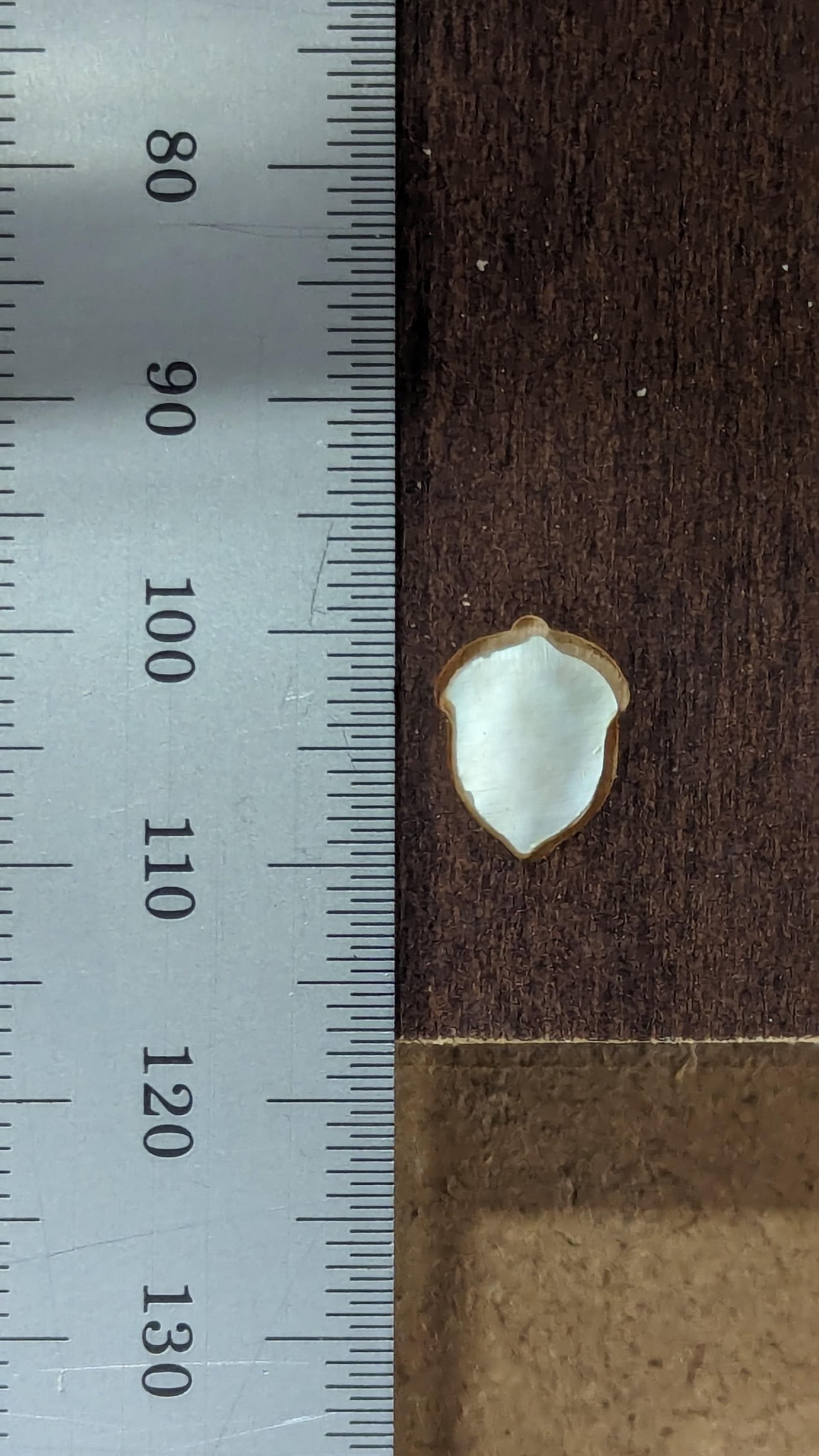
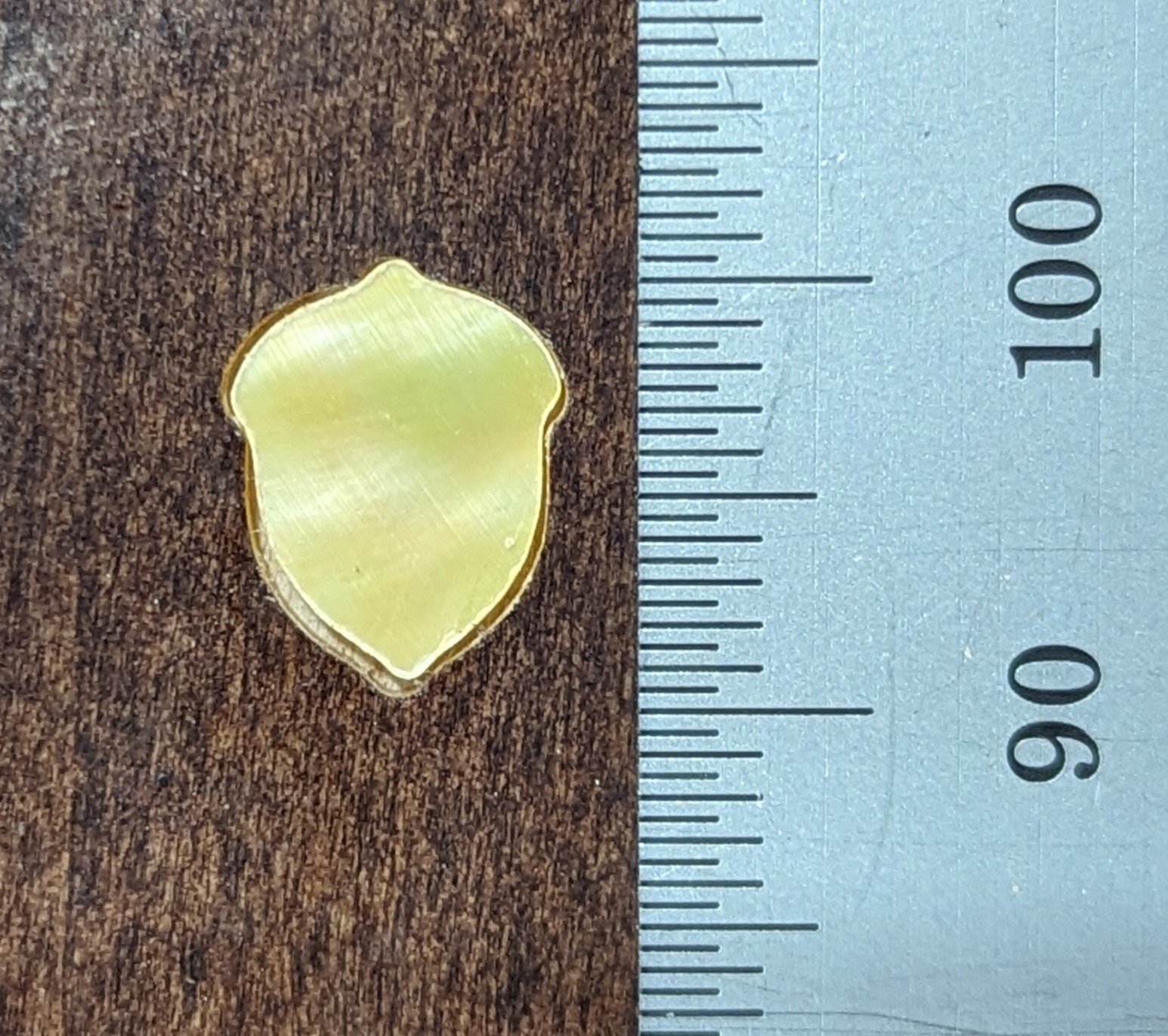
I’ve been tring to cut a simple acorn pattern. It’s pretty small, about 10mm tall. When it cuts the cuts are not symmetrical. I want to do maybe some test cuts for analysis.
Rambo 1.4, MPCNC approx recommended size.
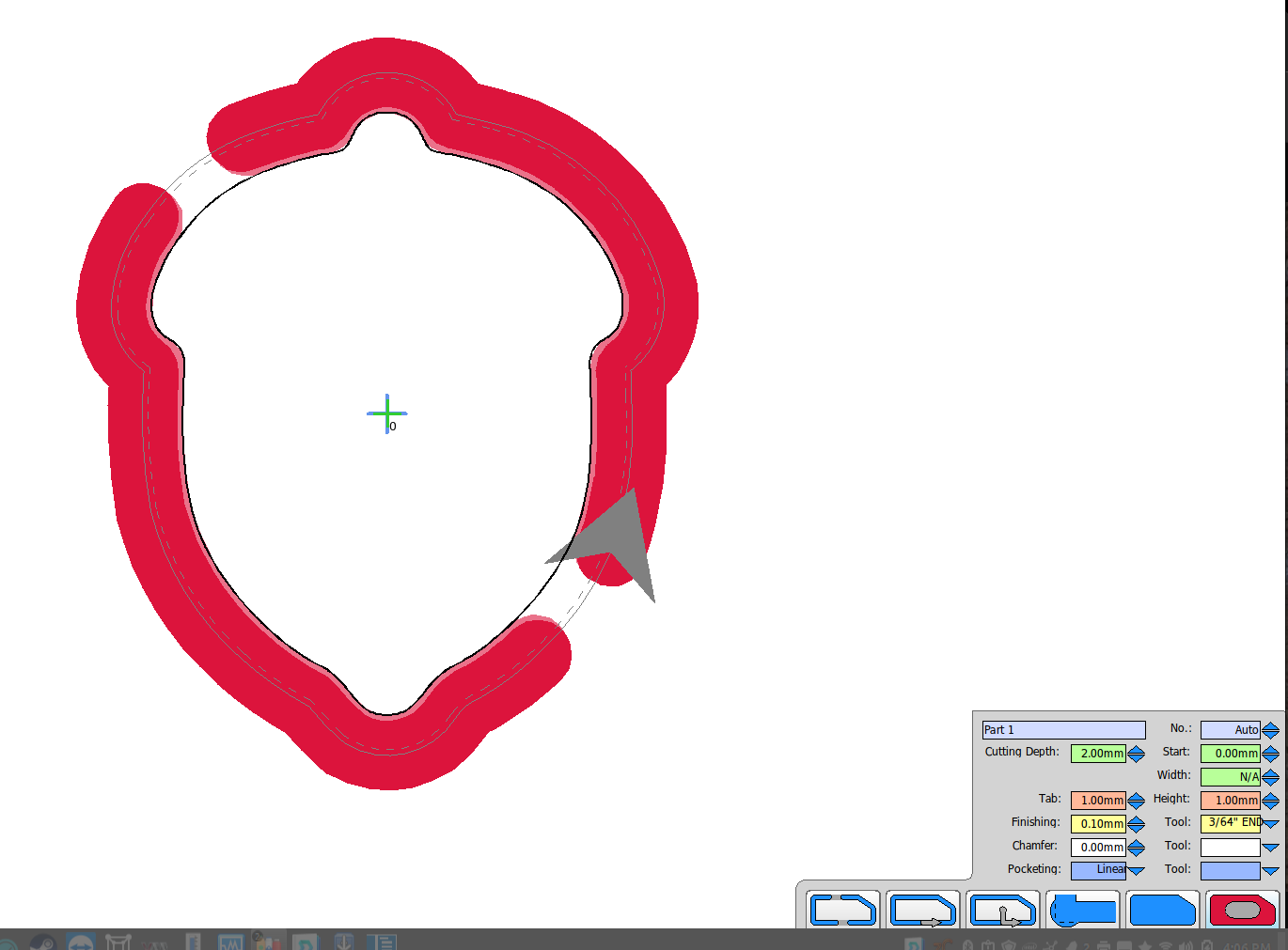
I started with inkscape using symmetrical paths. It Looks symmetrical in inkscape. The part cutout also looks pretty good in Estlcam. So it appears to be the cutting I think.
I am cutting out of Mother of pearl. I was originally having problems with the double stick tape not being strong enough and things moving so I slowed it way down to 3mm/s and added tabs.
I got 1 good one, which I think was luck. But it does make me think the tape is just not strong enough for such small parts. Perhaps I could try the superglue/masking tape method.
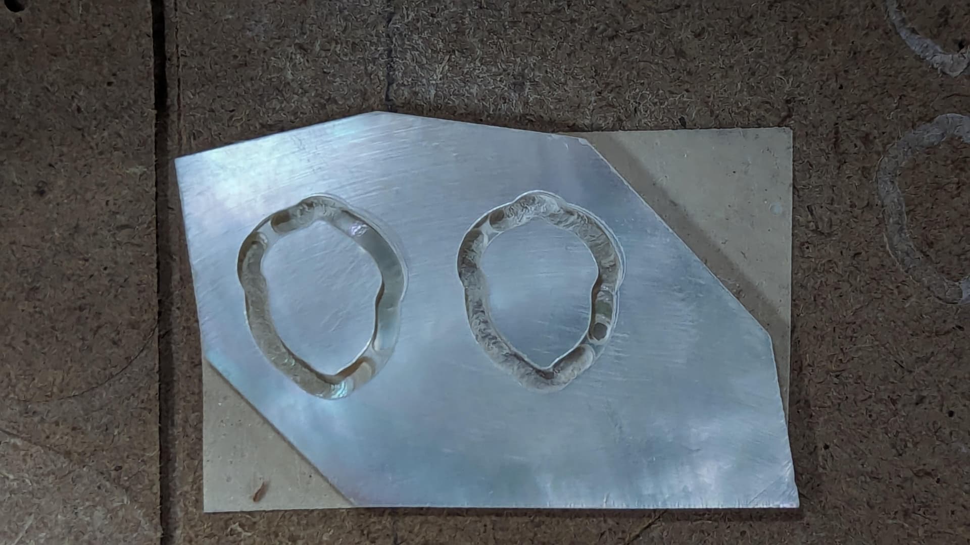
A second issue I do not understand may come into play here. When I used the SAME acorn svg for both hole/pocket and part even when I do not “widen” anything I have approx 0.5mm gap. I widened the part by 0.5 mm beyond the line and cut the pocket to the line it’s pretty close. But since the part is not summetric I really cannot evaluate.
Just trying to decide what to test to further evaluate?
so thoughts
go even slower
cut out a larger shape to test trueness (more tape)
cut out a perfect circle part and pocket ?
Other causes and tests? Could something out of true need tramming up? THings are cutting really well and letters look great. I have never done a leveling.
I am doing conventional (I think, never changed it) cutting. It is going counter clockwise around the part (not bit spin). BTW I did measure the bit is about the true size. 3/64" but accuracy with calipers at this size is a bit iffy. I’d have to test again to answer what happens if I remove the finishing pass. Thats another test. But… the finishing pass is only 0.1 mm which leaves 0.2mm total thats a bit light for 0.5mm unless the bit IS off in diam.
That sounds wrong. Climb milling should leave oversize parts and undersize holes (leaves too much material behind), and conventional milling should leave undersize parts and oversize holes (takes too much material away).
I can’t find an answer from searching. I do not see it in any parts list or the assembly instructions. I find discussions in the forums but no details.
BRIEF: no issue found. Problem disappeared. slowed it down and symmetry fine. Bit measurement wrong and fixed. Still gaps.
Details:
GRUB screws were tight but I got another little click on 2 of them. I do not have threadlock.
I redid tests in soft materials and the cuts were fine. In wood they were fine. In MOP they were also fine. So I can;t really say what the problem was but it is no longer happening.
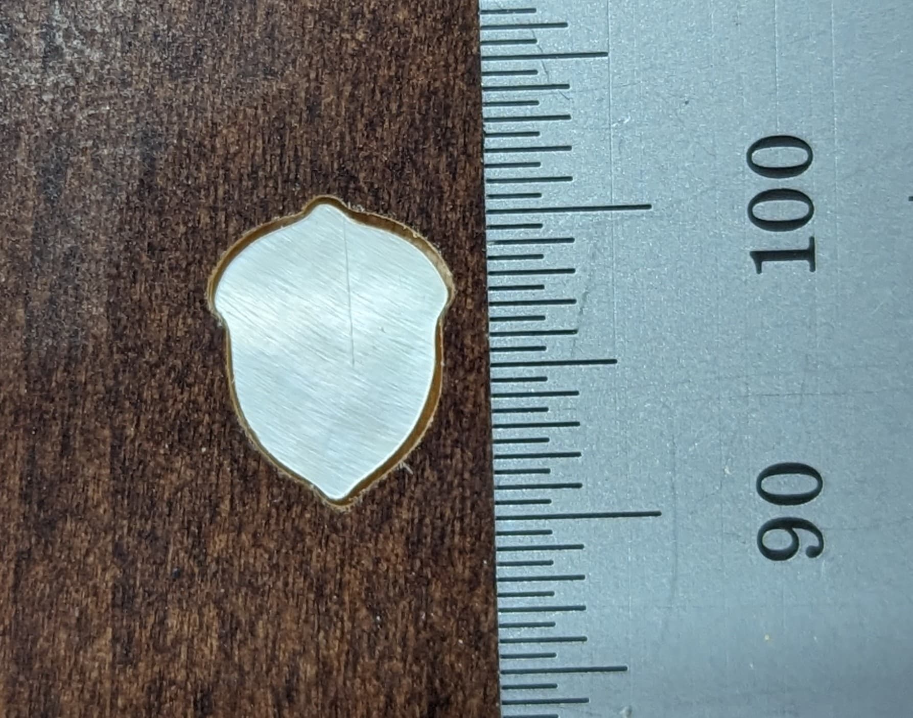
As far as the pocket size goes, I figured this is exactly what would be happening if the bit were wrong. Just as others pointed out. So I remeasured the bit and realized if I press solid its like .045 inches (3/64" - as labelled - but if I just grab the measurement at hit first touch it’s closer to .055-.058 ish.) I reworked all paths in ESTLCAM with bit set at 1.4mm (1.397mm=.055inch) and recut both the parts and the pockets to test fit and see how close they are. Previous comments said we can get gaps without finishing passes so I cut BOTH the POCKET and the PART with a finishing pass of 0.1 using the same tool and a slightly faster speed. I did WAY slow down the cuts just to be safe in MOP 3.5mm/s and 5? for finishing pass.
Flipped over to show the symmetry works pretty well now. I’ll have to keep an eye on this.
When I looked at this in the shop it looked awesome. It fits great to the naked eye (without glasses). But looking at it again here, it is still like maybe 0.7mm off total? I thought about it and figure it the bit entry it too small vs actual diameter, estlcam would make the pocket wider than expected. So I could make the bit meansurement entry a touch wider and see if it closes. I could see that maybe the the but could be as much as maybe 1.06mm max…055 inch (1.4 mm) → .06 (1.524mm). Thats only a difference of ~.124mm per side of cut so max ~.25mm. Which doesn’t look like enough. I don’t think mismeasured bit is enough to fully explain this.
I guess it’s also possible the bit is also not “perfectly” centered as well and when it spins could also make a wider gap. Hmm. I guess I could just cut an outline or straight line and try to measure that next.
The question is, is it “good enough” for my inlays. Perhaps. If I could close half that distance i’d be happy I think. I can continue to play with oversizing and undersizing I suppose.
Inlays are easier with a V bit and a carve operation, because there is some room for error then. I don’t know whether that works for the pearl as well though.
Oh right, I forget email replies do not work. Try this again…
Thanks for the reply and the tip. as far as feasibility on MOP to v-bit inlays. Its doable but the thinner it gets the easier it flakes and sanding the surface is a risk to ruining the effect. But its doable with care. Though its often very thin 1mm or less and requires precision anyway.
V bit also would require me to figure out pin point precision with tool changes. Something i have not been able to understand. I’ve read forum posts but I just do not see how you can get RELIABLE positioning with a system that inherently slips. My best guess is to see if leaving the system ON during change and hoping movement during change is actually captured in the XYZ coordinates tracked by the board. Of course unplugging the spindle for safety. Otherwise I just don’t see how we get pinpoint precision here.
I’m growing a little with each step. Just started to get into this accuracy evaluation. And really that’s the issue here. Are these machines accurate enough with rigid steel pipe at default build size or am I expecting too much? I would guess this is doable and it’s just a matter of taking the time to dial it in. ??
Glad to hear. I am a decent troubleshooter and think I can narrow this down. I have planned some cuts with circles to figure it out. I figured a circle eliminates the rounding oddness with offsets and helps understand squareness/true.
I remeasured the bit with a better calipers and got a little bigger .061 inches which helps close the gap a bit more. I can out a PART and check dimensions and also cut a slot to check slot width to verify bit size again from the cutout perspective (i.e. include wobble/errors) measuring the actual resulting size. Then cut out pockets of varying offsets (w & w/o finishin passes to evaluate that potential issue and see how it goes.
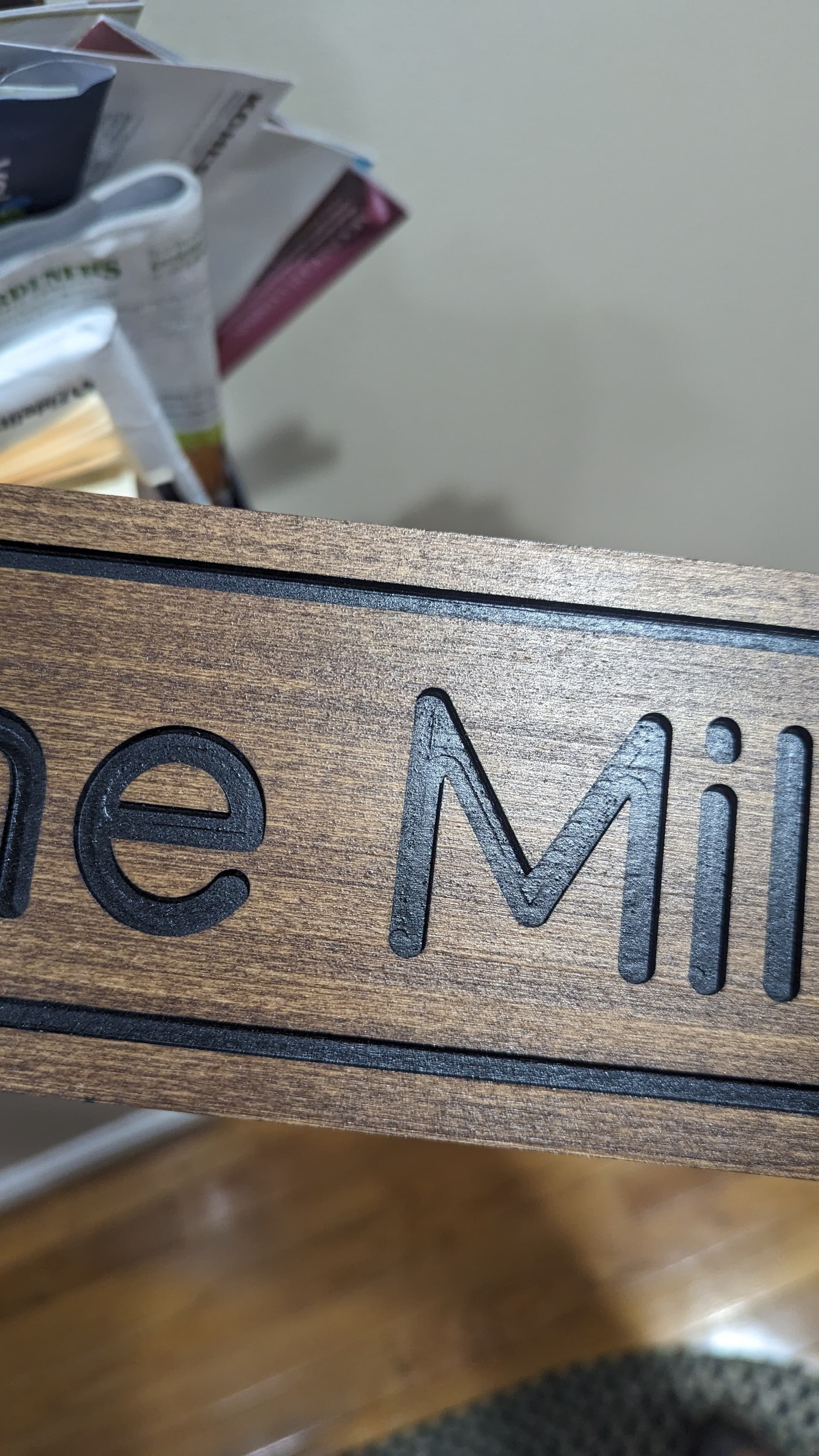
I do think I am slightly off on the (tramming?) - vertical Z’s as the bottom of my slots are not “perfect” when there are multiple passes in an area I see marks (Screenshot below). I also never ran a flattening of my spoil board (oh horror!). Or perhaps some kind of Z slipping. As shown here: