Yeah, you would have to put a spoil board on top. Lot of work but would make a really stout machine. Maybe something to think about for a smaller form factor design (i.e. mini-MPCNC). 
1 Like
Just realized @MakerPipe’s owner Dave is part of the V1E tribe ![]() . Dave’s probably seen more uses of EMT than anyone, ever…
. Dave’s probably seen more uses of EMT than anyone, ever…
Now that @jamiek’s probably 80%+ done, is now a good time to pivot to EMT conduit and MakerPipe fittings?
Curious if a stiff in torsion table/workbench design would be useful to V1E and broader MakerPipe community. Maybe MakerPipe community have great solution(s) already?
3 Likes

5 Likes
I wasn’t going to say it, but now that you’ve raised the stakes, I would point out that @turbinbjorn’s floor or a similar poured surface won’t be truly flat. (In fairness, @turbinbjorn only claimed “reasonably flat”.)
A poured floor or table top will tend to match the curvature of the Earth.
2 Likes

Haha! You win.
1 Like
Thanks for being fair! 
I wonder how big a poured surface has to be before you can measure the curvature of the earth!
2 Likes
Minor update:
Added conduit to brace the legs and it has decent stiffness but not fantastic. Going to worry about that later.
Added power strip and E-stop button in series with power cord to gantry. Gantry power cord hangs freely off the side and there’s nothing for it to catch on.
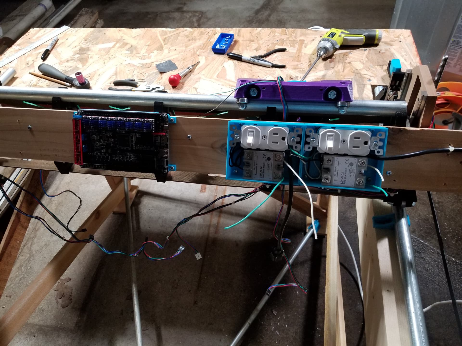
Added plank of cedar (pretty lightweight) for mounting all the stuff to the X axis, and added two outlets, each with a switch and SSR for manual or software controlled spindle on/off.
Mounted the BTT Octopus and all 8 drivers with jumpers in UART mode. The Octopus board has jumpers between the DIAG pin and the endstops, so clipping the DIAG pin is not necessary (I think).
I still have to mount the 24V power brick, raspberry pi, and a buck converter, and make a bracket to hold the cable chains.
And I will make covers for the electronics too so they’re not out in the open catching debris.
My cable chain wont accommodate the router power cords, but I have a few thoughts for managing those.

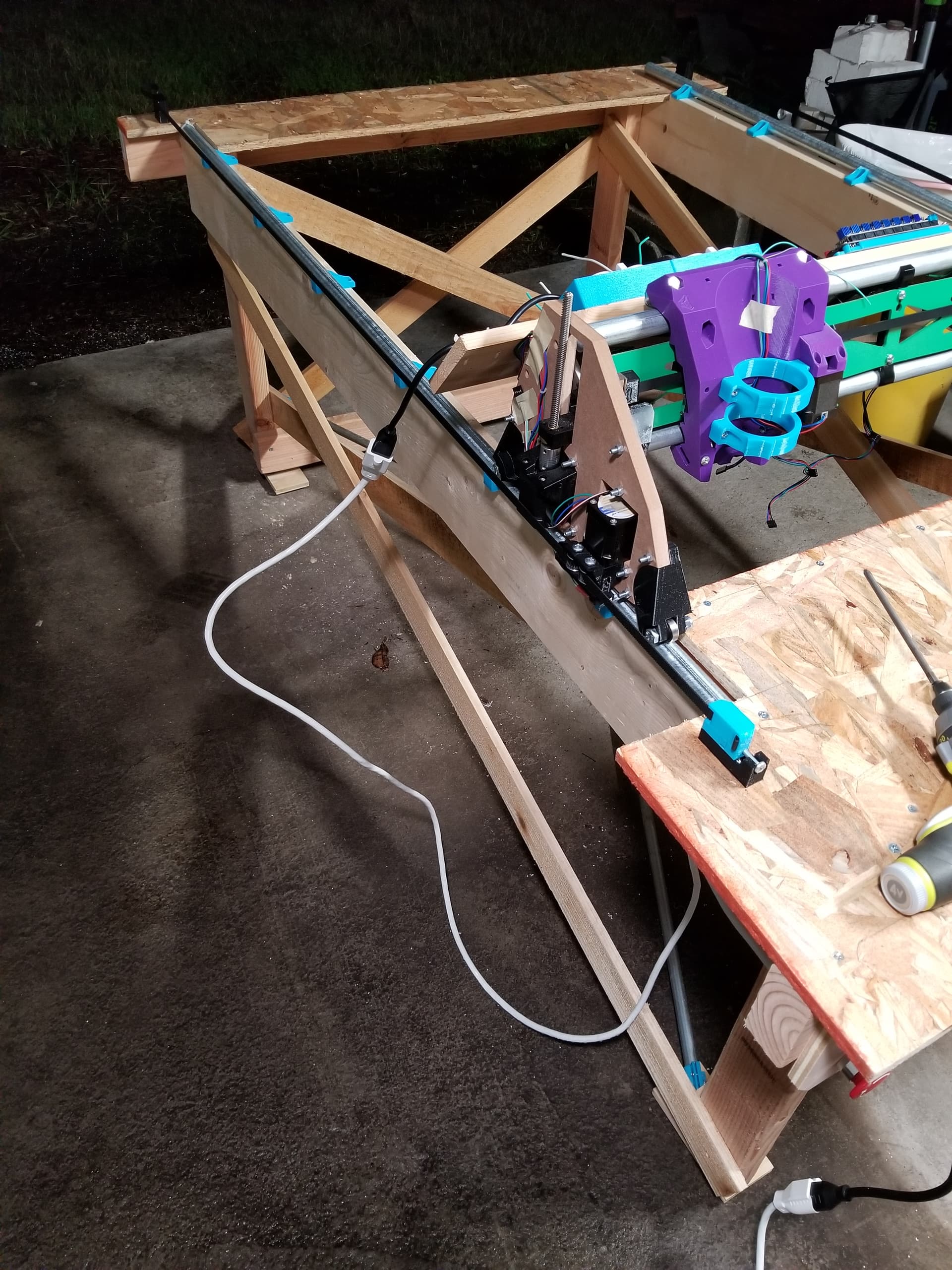
My preference would be to keep the gantry as light as possible and not hang all the crap on it, but to be removable I really want to minimize the electrical connections. The belt attachments are very nice and with a single 110V power connection I should be able to fully attach or detach the gantry in maybe 10 seconds.
5 Likes
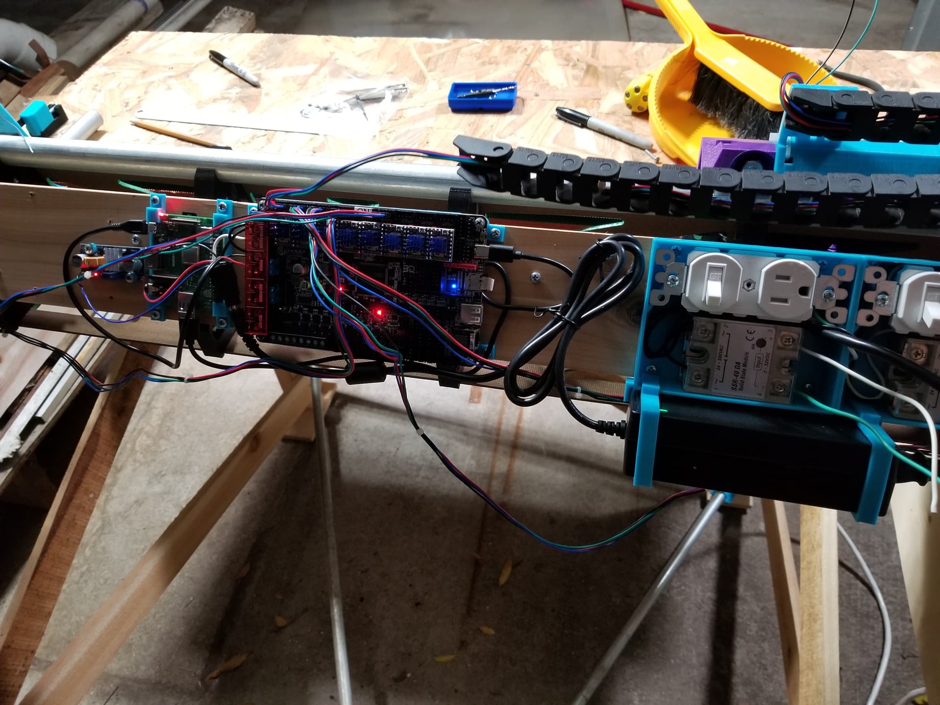
Ok, got it moving

Since last time I have installed 24V psu and controller and pi and buck converter.
Firmware doesnt support both X carriages yet, and endstop wiring not yet complete.
Probably going to start another thread for BTT Octopus firmware.
5 Likes
Dual carriages working!

Unfortunately, Marlin’s built-in Dual X Carriage support requires two extruders to be defined, with no obvious workaround. Thankfully I have two spare axes I could dedicate to keep the firmware happy. I’ll need to revisit that when I get to the 4th and 5th axes (maybe 2024?).
10 Likes
That is a good sign that you are the first person to use Marlin to make a IDEX cnc machine 
5 Likes
Back during the Apollo days, NASA had to simulate zero gravity by floating test capsule simulators on a cushon of air on the world’s flattest surface. They had to take the curvature of the earth out of their floor because it caused the machines to not fly straight. It had a “mountain” in the middle of the floor that they’d slide down. It was like a fraction of a millimeter or something crazy like that.
The floor is 86 by 44 feet. It was poured that big to fit space station modules on it to practice putting them together. The floor has stayed flat for around 30 years.
“We have tested and trained astronauts using this concept for decades, and we also can test hardware,” said Bryan.
Bryan helped pour this one and the flat floor before it, and when they say flat, they mean extremely flat.
“95% of the floor is plus or minus 3.5 thousandths of an inch,” he said. “That is half the thickness of printer paper.”
It’s layers of an epoxy compound on top of an isolated five-foot slab of concrete. It was selected by the corps of engineers to make it as stable and flat as possible.
3 Likes
In Kerbal Space Program there is a runway that is perfectly flat, and the curvature of the planet is enough that vehicles have a very slight tendency to roll toward the middle of the runway.
In other news, I’ve got homing of X working. The original plan was to home X2 to the left and touch off of the first carriage, but I had to abandon that approach and home X2 to the right. Homing X2 to the left is possible but it causes it to use the XMIN endstop, and it would require some extensive changes to fix.
Not a big deal, since I would probably need to calibrate the offset periodically anyway.
I am having some Z binding issue that I need to work through, and I need to (finally) make a mount for a DW660.
I’m also accumulating ideas for improving the table and after everything works I will probably build the table over again to incorporate the things I’ve learned.
4 Likes
Turns out Z binding was not really an issue. The SKR Octopus has 8 drivers and 9 plugs, where the third driver has two plugs wired in parallel to drive two Z axes. I had mistakenly plugged Z1 and Z2 into the 3rd and 4th plugs (wired to a single driver in parallel) instead of the 3rd and 5th plugs for true Z1 and Z2.
I created a DW660 mount based on the Primo mount and it feels pretty sturdy. I posted the model here on printables.
I think it’s time to build the interior of the table to support a spoilboard and workpiece.

8 Likes
Curious how you end up supporting the spoilboard, looks like you’re making a drop table too? Using any of the spare Octopus driver slots to automate spoilboard height/leveling ![]() ?
?
1 Like
Not planning to use extra drivers to move the spoilboard. I’m thinking I’ll have ribs attached to the frame and surface the tops of the ribs to be level with the gantry, and then mount a 2’ x 4’ sheet of particle board on top of that. I’m hoping by surfacing the ribs I won’t have to surface the entire area of the spoil board.
Right now the extra drivers are not usable because IDEX requires having two extruders defined, which consumes two steppers. I would like to use the extra axes as rotary axes someday and I’m guessing it will be easier to edit the pins files to assign ‘dummy’ pins to extruders and trick Marlin into thinking that it has 10 steppers instead of 8. Then the rest of the code can be mostly untouched. The alternative would be to refactor the IDEX stuff which is doable but maybe a longer term goal.
4 Likes
Okay, got the sub-floor installed and flattened it and installed 24" x 48" deck (entirely reachable by first tool but not by second tool).
Adjusted steps per mm (was off only slightly) and squared it and installed a few threaded inserts for securing an upper spoil board, and flattened the spoil board (was nearly perfect already since I had flattened the sub-floor).
Got some scrap and set up a job cutting two concentric circles in Estlcam. I had to manually insert some gcode for tool changing since I’m using M42 to turn the tools on and off, and currently I have to park the tools manually (meaning manual insertion of gcode).
I got the tool offsets close by eye, and then after a couple iterations of tweaking the offsets, it’s pretty good:

I was expecting to have to use workspaces (G54, G55, etc) to accommodate the offsets between the tools, but Marlin already has the concept of tool offsets in the IDEX code, so I can define the offsets (including Z) with M218 T1 X__ Y__ Z__.
The bad news is there appears to be a bug in Marlin when switching tools and switching workspaces. It mostly works, but when switching T1/T0 and G54/G55 it leaves it in a confused state where the coordinates are not correct. The job in the video above is supposed to switch back to the first tool (T0) and move back to above the workpiece origin (center of the circle) but it doesn’t. Luckily I’m not switching more than once and for the video above it has no effect, but if I were to switch tools multiple times it would be an issue. So I might have some firmware work to do. (Maybe if Marlin obeys the G53 semantics then I won’t need more than one workspace and it might not have an issue.)
Also I should mention I did get rotary axes A and B working, meaning I can give G1 A__ B__ commands and it will move two more steppers if I connect them, but I don’t have the mechanical part of the 4th/5th axis so that will have to wait.
10 Likes
OMG! It lives and it is amazing. Makes me dream of my YZ plate production getting sped up by not having to do tool changes…
Mind-blowing work as always!
2 Likes
I’m trying to think of the most compelling example to illustrate in a public video, but all the jobs I can think of can be done using a single tool change mid-job, which might make it seem sorta ‘meh’.
Batching out a lot of short jobs over and over again could see a huge benefit since each cycle would otherwise require two tool changes (and setting Z heights). That’s one option.
What am I not thinking of? V-carve inlay with lots of layers is a lot of alternating between flattening and carving, but seems like it might distract from the point of the dual-tool setup, and besides it needs gluing in between, which makes the efficiency gain seem smaller (relative to elapsed time).
Maybe some 4-sided milling? Coarse/fine (rotate) coarse/fine (rotate) coarse/fine (rotate) coarse/fine might highlight what a pain it would be to have to switch tools manually.
Other suggestions?
2 Likes
Can IDEX help to almost double production speed for single tool batched parts, with same tool in both cores? Would the resulting machine cost of material volume cut/carved per sec be compelling to business owner?
4 Likes