Rather than a down cut, I tried a straight bit (brand new). I tried that along with doing the cut in a single pass. I still got crazy tear out from the top. I guess either the hard board I bought is somehow different, or I’m just not using the right settings.
Going from memory, I think Z1 and Z probe are backwards there
What I have in the graphic is definitely working for me now.
1 Like
Ok. I’ll defer to someone who has it working. I had it workimg, but pulled it out for the Duet.
Got my SKR case assembled and mounted. Got my two additional Strut plates cut. Got one cleaned up (removed tear out). Will need to clean the other one, and then paint them both.
In the meantime, I’m transferring video to be able to show some cool stuff such as the SKR case assembly and show off.
3 Likes
New video, plus, got the new SKR case posted on Printables!
LR3 control box case for SKR Pro 1.2 with TFT35 E3 — based on V1’s Blank Case CAD files
FREE STL FILES AVAILABLE HERE: LowRider 3 CNC - control box case for BTT SKR Pro 1.2 board and a BTT TFT35 E3 touchscreen (v1.1) by Doug Joseph (design8studio) | Download free STL model | Printables.com

5 Likes
Me too. I had to come looking for an answer to an end stop issue this evening, and mine maps exactly like your diagram shows, not how it is written in the docs. Glad I’m not going crazy
1 Like
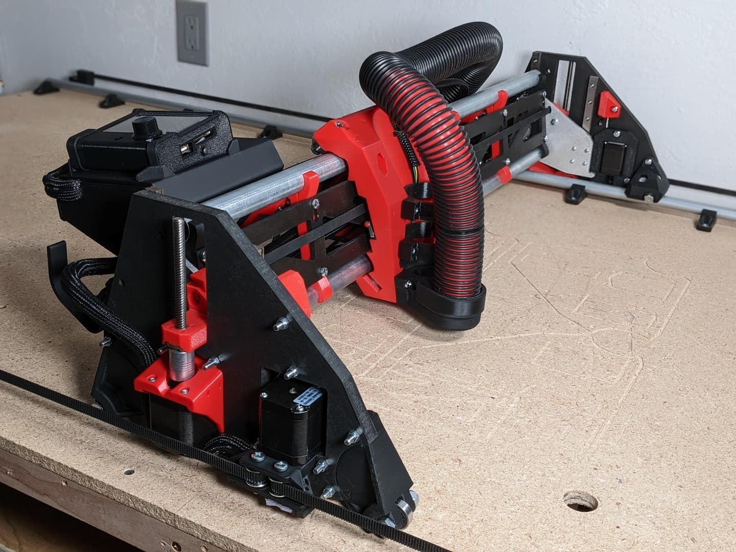
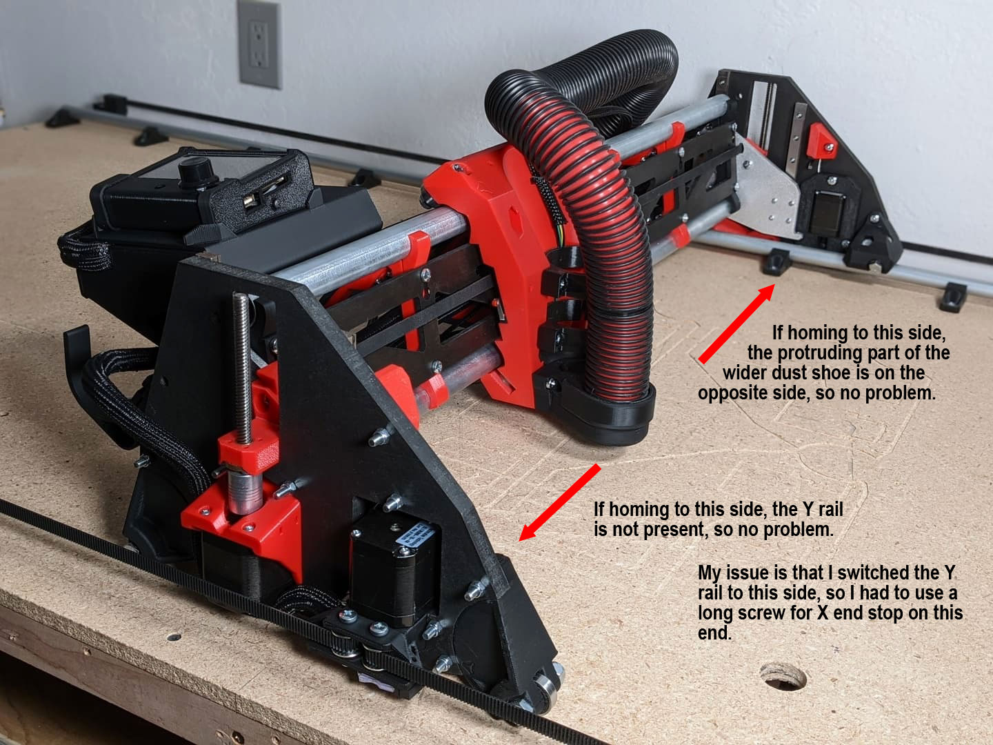
Yes, I flipped which side my Y rail is on! So, if you do not, you may not need the X end stop screw fix like I did.
Flipping which side the Y rail is on requires printing mirrored parts for the wheel corner attachments and their corresponding parts on the Y rail roller side.
Sorry, I did not think to mention that change explicitly in earlier posts.
Compared to the front of the machine, you still want the homing to be to the left, so unless you also flipped either the XZ plates or the stubs for milled parts, as well as the core, homing will still be to the same side, and therefore the larger dust collection part will still interfere with X homing without the long screws.
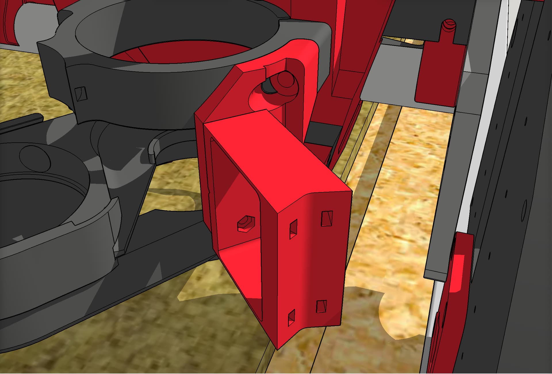
LR3 Cable chain mount - printed parts
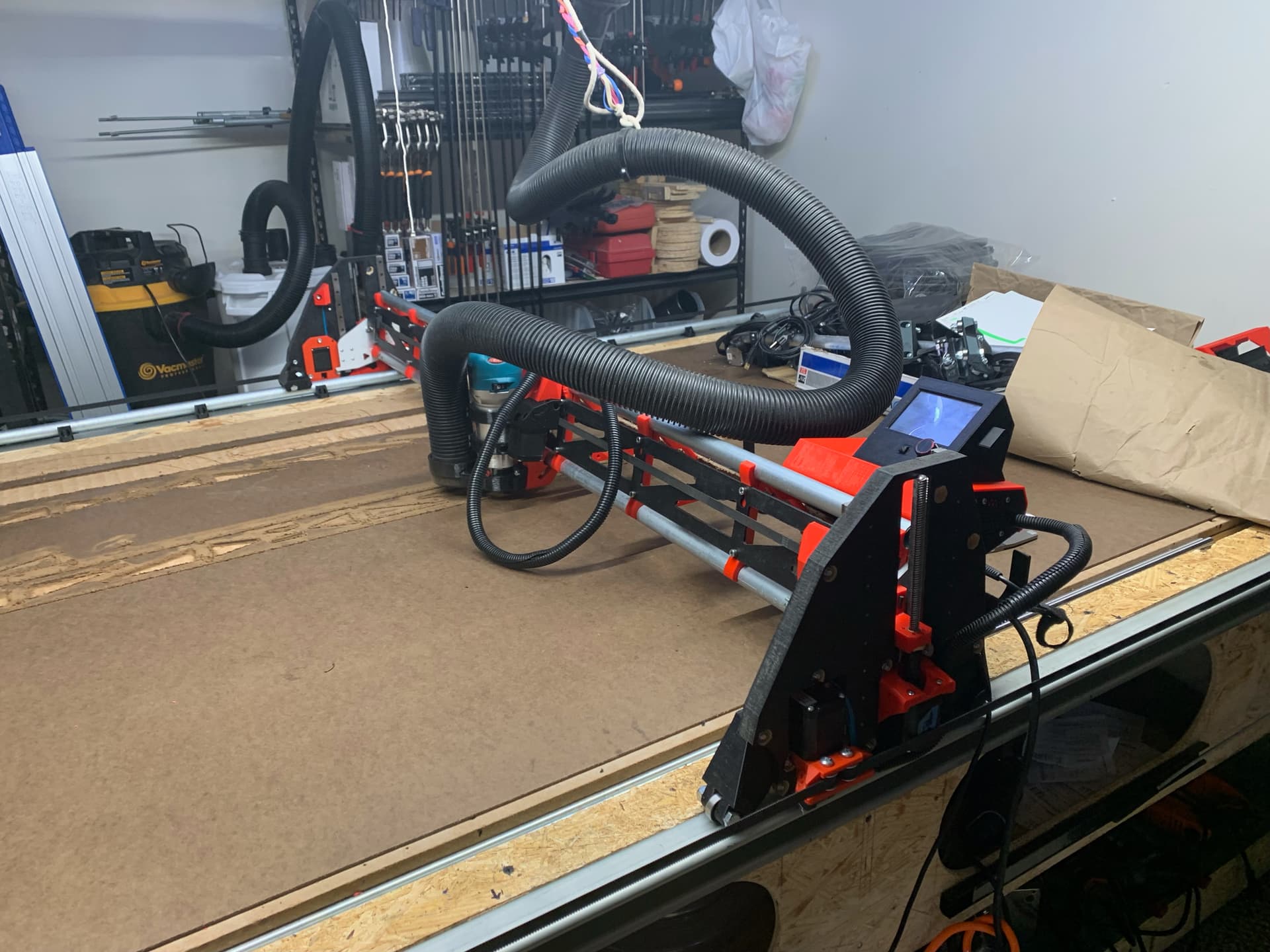
I really like the LR3. It is a truly impressive design. My specific situation is such that I have needed to make a few minor tweaks to the plan.
The normal plan is for clever use of the vac hose — having it serve as the cable guide for the router’s power cord and X axis wiring. However, since my dust collection hose comes down from overhead, I’ve had to install a cable chain for guiding the power cord and X axis wiring. Since that is outside the normal plan, I had to design up a handful of printed parts to mount the cable chain. I now have my designed parts printed and installed. If anyone else would benefit from the designs and wants them, they are here:
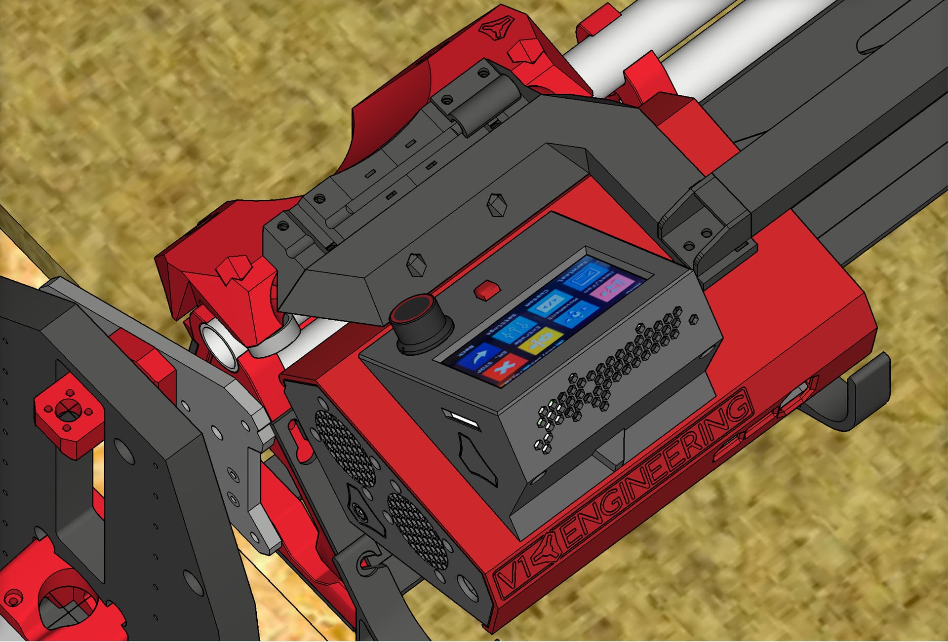
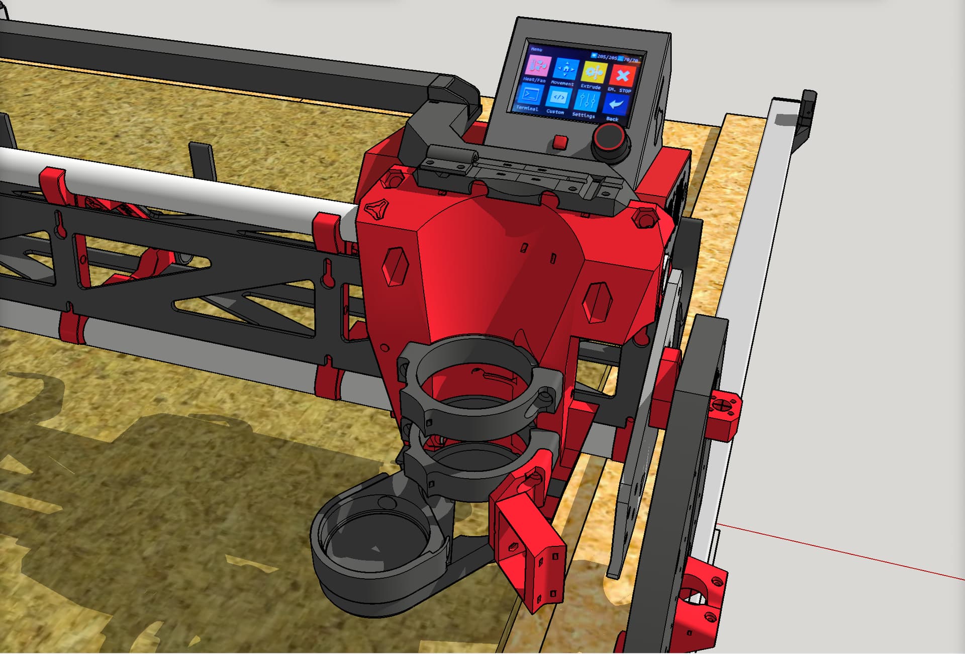
Overview:
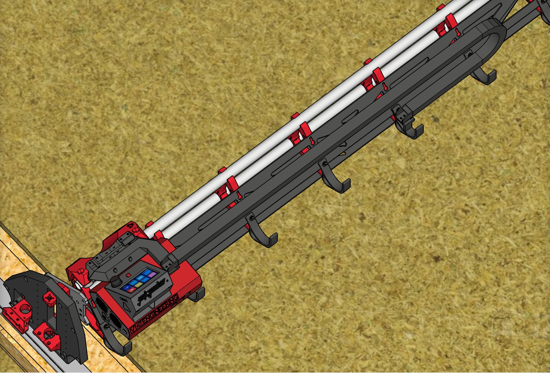
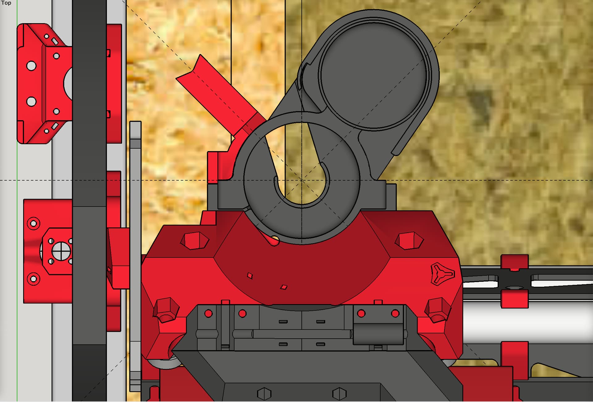
Looking down on the upper mount setup:
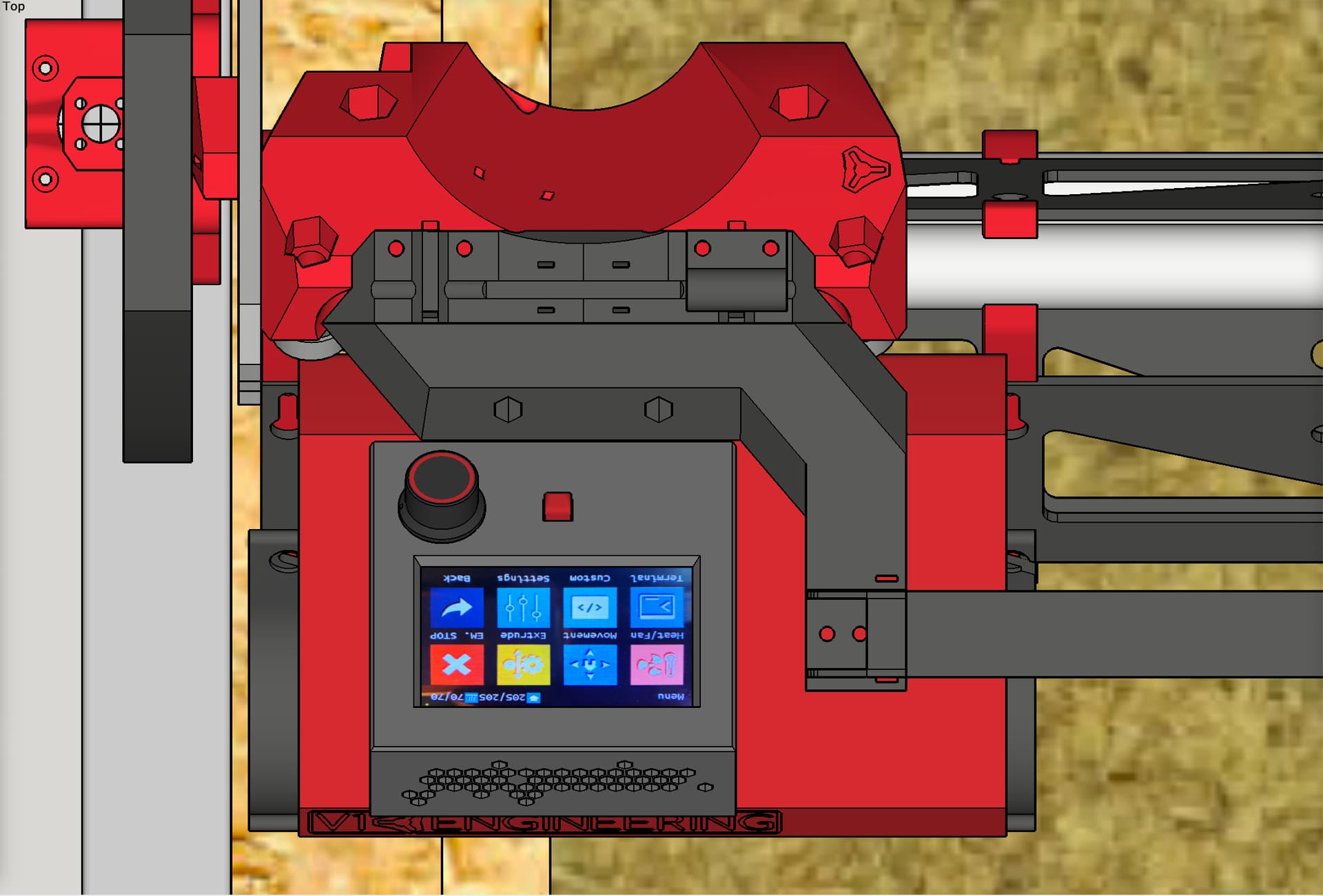
Birds eye view of the upper mount setup:
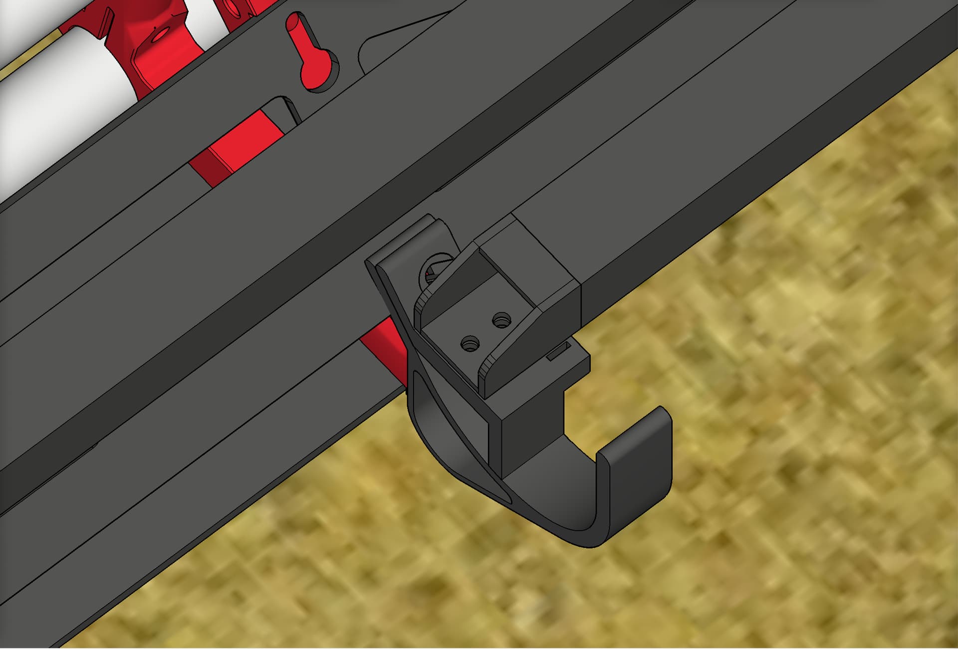
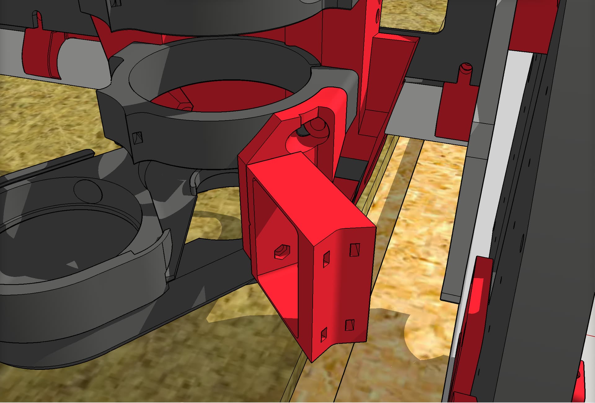
This little clamp-on piece holds the router cord secure so it does not bump against the side assembly when X axis is tight against home:

Close up of lower mount part:
See above. Since (I think) you said you are using a dust collection system, I’m not sure if the above would benefit you, but maybe. STL files are here:
Maybe you and @DougJoseph can look at the docs now and see how to improve them. This is from the docs:
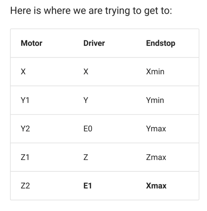
At first glance, it looks wrong compared to the diagram above, but the driver column is mean to point out which driver good to which motor. The endstop communion is right (afaict). The skr pro board labels xmax, ymax and zmax as E0,E1,E2, but that is a bit irregular.
Maybe I need another column for the skr endstop names?
@jeffeb3
You all have done a fantastic job on documentation. There is a lot of ground to cover and there is a lot of documentation. Whenever a board is an outlier in how things are described, it adds a challenge. There can be other challenges, such as the kit builder is green regarding terminology anyhow, and sometimes, like me, the builder is tired, which can take a few IQ points off. Still, I think an image / illustration like what I posted would have helped me, and so I offered it as a possible help to others. The old saying is “a picture is worth a thousand words.” Feel free to add it to the documentation. For each board that is sold in a kit, that probably should be considered a “supported” board. I don’t know how many such boards there would be, but it would be great if illustrations like the one I posted could be added for each supported board. I do understand that no matter what you do, there will still be people who either don’t see it, or don’t know it exists, or do see it, but don’t connect what it’s for, or still have trouble. 
2 Likes
That probably would help too. I still think my illustrated image would be the most effective.
1 Like
Yes, adding the skr port name would make that chart complete and not look wrong ‘on first glance’
2 Likes
@jeffeb3
Thanks for being so understanding.
Of course. We have the same goals. Users are trying hard to build the machine and get to having fun. The docs are trying to get them there too. Things like this are generally an easy fix.
It gets a little trickier when different users need different information. Some people follow the text to the letter. Other skim it and look at the pictures. Others (myself, probably) will only read it if it is short enough.
The longer the docs, the more difficult it is to keep up to date too. So there is some reasoning behind keeping some data only in the forums.
Luckily, when things fall through the cracks, there are a few dozen people willing to help out here.
The question is always, “Did this person just get lost?” Or is it, “100 people have gotten lost, and this is the first person to say something”. There isn’t a good way to tell (at least until a 2nd, 3rd person speaks up).
The picture is really good for anyone using the skr pro. I would be happy to add an skr column, but I will let @vicious1 decide if the skr image is good to add, or if it would be a problem for the rambo users.
4 Likes
Sounds good. My thought was to make an image like that for each supported board, and builders could just go to the one for them.
2 Likes
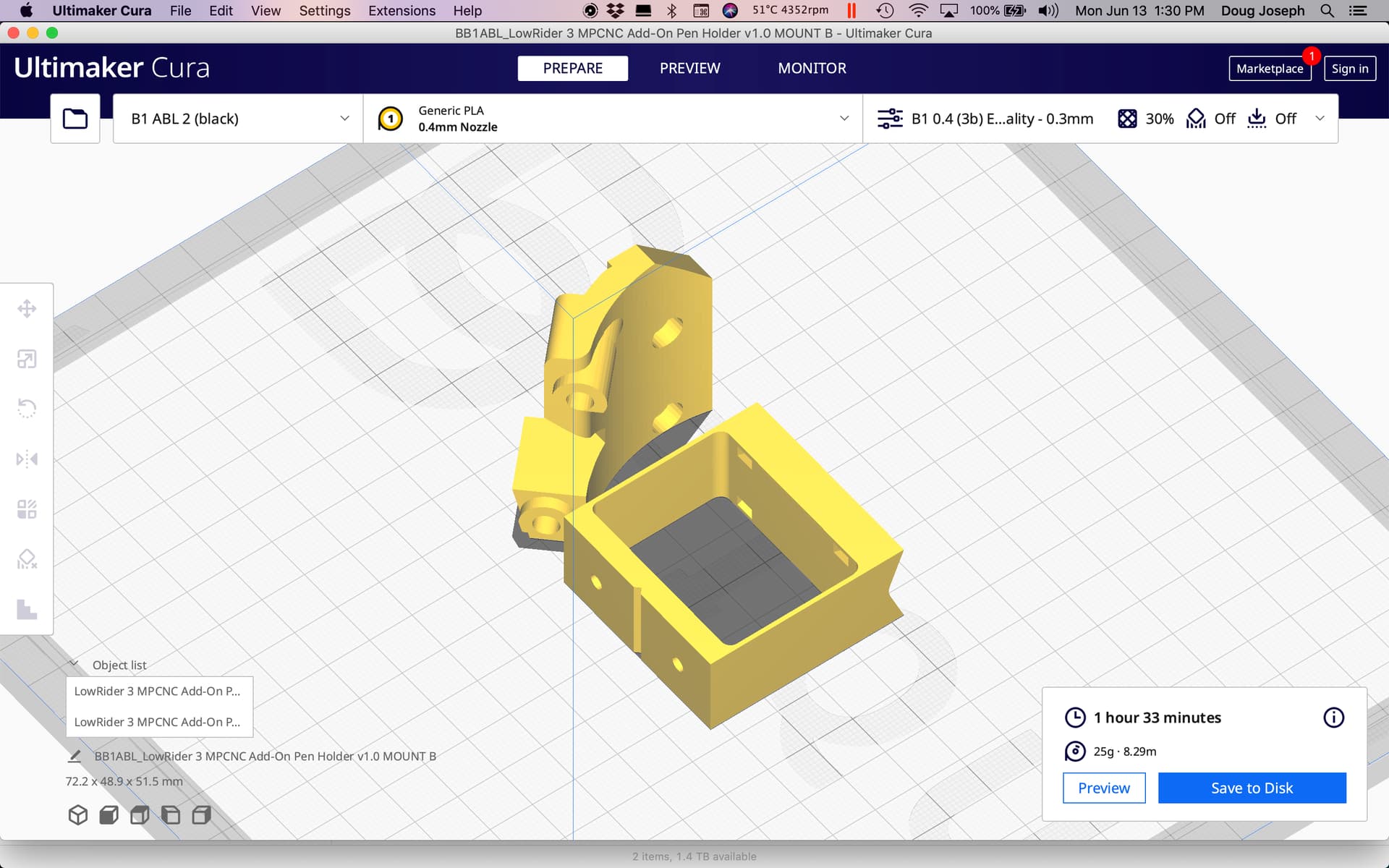
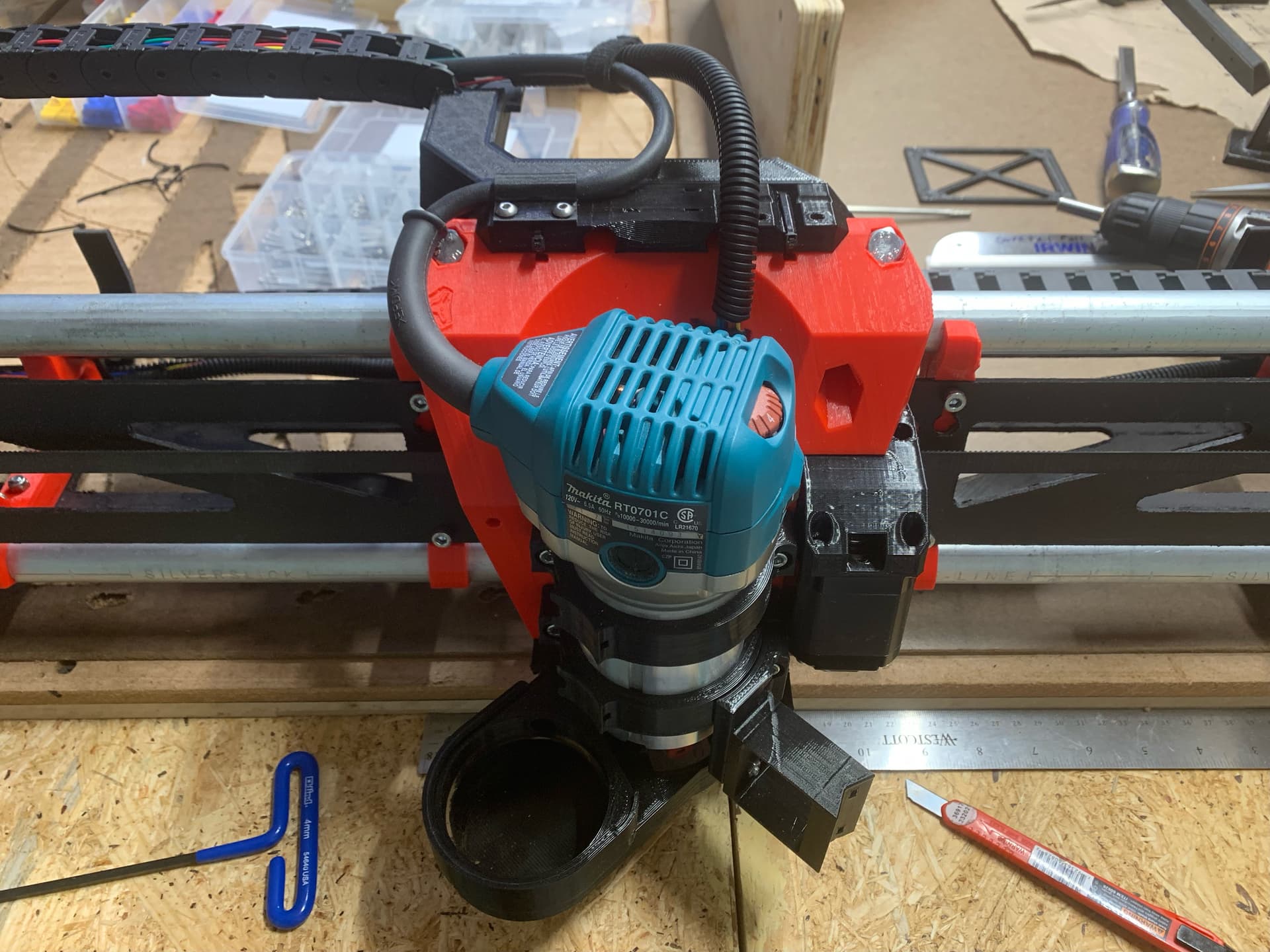
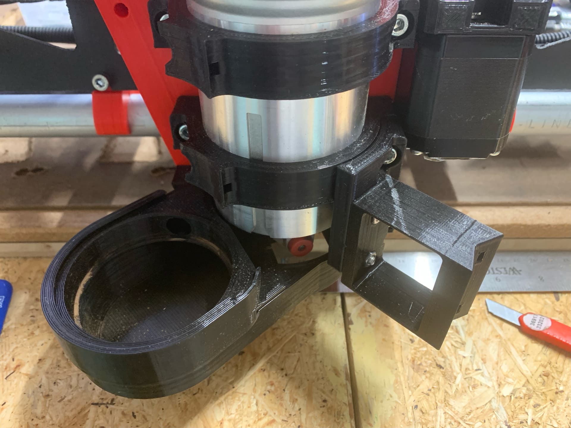
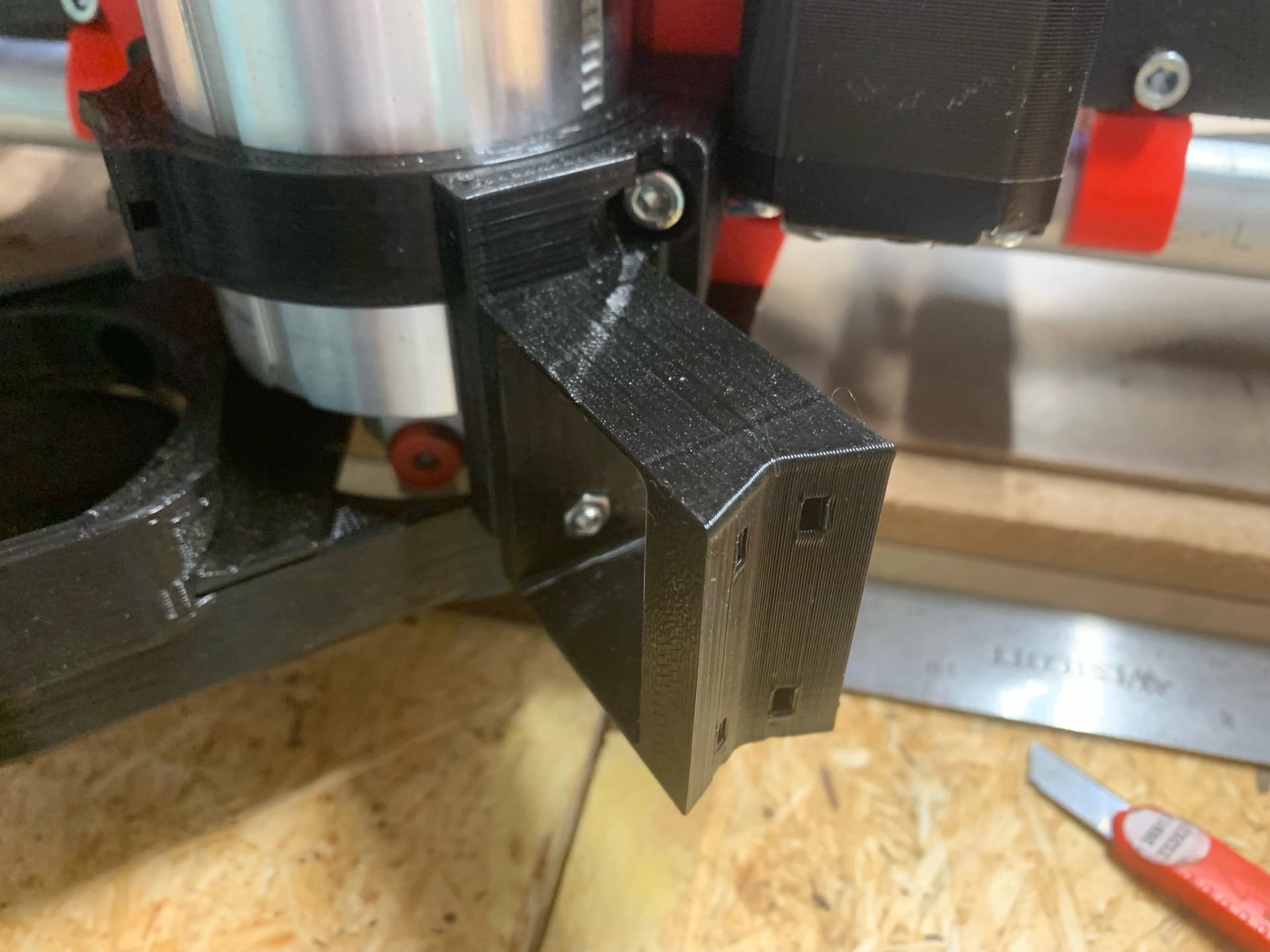
Just updating my build thread here. Got the pen holder / drag knife mount conceived, modeled, printed, installed, and posted for others in case they want to use it.
UPDATE July 3, 2022: in using the pen holder, I think its flex arm needs to be narrower. It takes a little too much force to flex it. Remix coming soon.
Details here:
Download here:
5 Likes