In your estimation, is 1/4” plywood better than 1/8” hardboard? I feel like it would be, and perhaps that would be enough to quash my twist issue/concern.
No I think we all did our testing with 1/8".
1 Like
I think hardboard or MDF is often better for dimensionally sensitive material, provided that it is sealed (painted is fine). Plywood still has some sensitivity to moisture and temperature and is less uniform in its adaptation.
This is one place where I was considering 5mm acrylic, though it’s pretty bendy stuff, I think on edge like this it should be plenty stiff.
I cut my first set of these in 1/8" hardboard, the current set are cut from 1/4" MDF with melamine. Also currently using 1" DOM steel, I think I could sit on the gantry now. Wouldn’t be very comfortable though  !
!
I suppose your beam is longer than mine, mine is 1206.5mm. I did re-do the CAD for it though, so no issues with stretch on the bolt holes. I am not sure that is the issue though, the stretch that you did shouldn’t reduce the screw grip much, which is the important bit.
Maybe a good idea would be to re-do the CAD, and cut your 1/4" struts first see if that resolves it, if not start printing your braces for the 1" steel. Flexibility is a geometric progression, so maybe there really is that much difference between my 1206mm and your 1425mm…
2 Likes
So I gather plywood not as good if comparing 1/8" to 1/8" — but what about 1/4" plywood to 1/8" hardboard? Still no better?
It’s also going to depend on what kind of plywood. Going with something “soft” like subfloor isn’t going to be as good as going with a close-grained hardwood like birch. Paint or stain will also change the properties quite a bit (Better in almost any case I can think of) so it’s difficult to make broad range comparisons. Keep in mind that many “hardwood” plywood also only have one ply of the specified hardwood on the outside for appearance purposes, and have different wood in the core. This means different properties dealing with heat and humidity as well as possibly reduced overall resistance to flexing…
But… It’s not really as bad as all that. 1/4" plywood is probably going to be superior to 1/8" hardboard in any functional respect that we care about. Regardless, sealing it is probably a good idea for any plywood under 12mm to keep it from wanting to warp on its own.
Be careful in what you’re getting. 5mm is probably ideal, actually. Full 1/4" (6.35mm) is the maximum that the machine will take without clearance issues on the front, and also the maximum that you’ll get an unmodified LR3 control board case to fit onto, and at that, it’s tight. While thicker material ont he bottom is possible, keep in mind that any thickness above 1/8" on the bottom starts to reduce available Z clearance, as it begins to stick out past the indentations in the braces. This isn’t likely to cause much grief, honestly, but I felt that I should add it for completeness.
2 Likes
@SupraGuy @vicious1
Thanks Dan, and Ryan, and all.
Dan, that explanation is helpful. I bought the plywood months ago at Home Depot, and as illuminating as the explanation is, I don’t remember enough about what I bought to get full help from it. I think it was some decent quality, so-called “cabinet grade” stuff and it has a decent finish on both sides. I have managed to keep it and other plywood I bought straight. I have some various different cans of stuff I could use for sealing it, including some oil-based enamel flat black paint. I had intended to use the black to match the “look.”
This plywood measures 5.17mm thick.
I just found a local Home Depot listing for 3/16" Tempered Hardboard Panel. I may do that. Or I may double up the 1/8" hardboard. 
@vicious1
You are a genius and the LR3 is amazing. I have no doubt that if mine has some issue, it’s due to me going off-script somewhere and not properly following the steps. I don’t for a moment think it’s the design.
Most of the plywood you get at either the blue or orange chruch is garbage. It’s full of voids.
I’m sure it’s true. I am not getting any voids with this 1/4" though.
Just to frame this in, you feel your twist in the center is worse on this as compared to your LR2?
2 Likes
My LR1 (which has a similar gantry to LR2) always was easy to twist in the middle. It never affected my cuts (AFAIK). But it also had a natural tendency to be level.
1 Like
Honestly, twist was not really on my radar before when I was using the LR2. What put it onto my radar was — due to the fact I mistakenly only cut one LR3 strut before I dismantled the LR2, I wound up having to do some cutting with only one strut. Lots of twist of course. Once it was on my radar, I checked for it even after I got the other two struts mounted. I saw a little (though not nearly like when I had only one strut). I may have had some twist on LR2 and just didn’t catch it.
That said, I still would like to get my LR3 as rigid as reasonably doable. I just now did a side by side comparison of a 1/8" hardboard strut and a 1/4" plywood strut. Just from a standpoint of “flexing” I think I’d be ahead to switch to the plywood. And I have these SS tubes leftover from LR2. And I really could use another 10mm on my beam’s length, which would require rebuilding it anyhow…
1 Like
No way to know for sure until you try it.
2 Likes
It’s a shame about the ¼" limit. I was thinking an 8mm laminate flooring plank could have been a perfect fit here.
2 Likes
I am making progress on extending my beam by 10 more mm.
I have the new struts cut and cleaned up (light sanding, removing furries). I just spray painted my new struts (black oil based enamel) and waiting on them to dry.
Coincidentally, the switch to a longer beam will also involve using my 25.4 stainless steel tubes from the LR2 (cutting them down now).
I have almost all the new braces printed.
Note: I know there are pros and cons to using capture slots for nuts on the braces. The main pro is ease of assembly. The main con (I think) is the potential for the capture slots to “strip out” and lose their grip on the nuts. A secondary con is if the nut is crooked the threads can get fouled. All that said, I keep the nuts straight by having a bolt through them while I insert them, and I plan to put a little epoxy on each nut to help prevent the “plastic strip out” issue. Thus, I am using braces I tweaked to have nut capture slots on all three sides. I will report back how it goes.
I am also still pondering (pretty intently) on whether to switch the X and Y axes with each other and if so by what means exactly.
I am seeking to document here my firmware edits & hardware changes, in my successful process of …
…swapping X and Y axes on a Lowrider v3 with dual end stops, with an SKR Pro 1.2 main board and BTT TFT35-e3 v3.
MARLIN FIRMWARE EDITS
In configuration_adv.h, there were five (5) edits. I changed the following:
- Uncommented “#define X_DUAL_STEPPER_DRIVERS”
- Uncommented “#define X_DUAL_ENDSTOPS”
- Commented out: “#define Y_DUAL_STEPPER_DRIVERS”
- Commented out: “#define Y_DUAL_ENDSTOPS”
- Changed “#define X2_USE_ENDSTOP _XMAX_” to “#define X2_USE_ENDSTOP _YMAX_”
Here are the “before and after” code sections:
BEFORE:
//#define X_DUAL_STEPPER_DRIVERS
#if ENABLED(X_DUAL_STEPPER_DRIVERS)
  //#define INVERT_X2_VS_X_DIR    // Enable if X2 direction signal is opposite to X
  //#define X_DUAL_ENDSTOPS
  #if ENABLED(X_DUAL_ENDSTOPS)
    #define X2_USE_ENDSTOP _XMAX_
    #define X2_ENDSTOP_ADJUSTMENT  0
  #endif
#endif

#define Y_DUAL_STEPPER_DRIVERS
#if ENABLED(Y_DUAL_STEPPER_DRIVERS)
  #define INVERT_Y2_VS_Y_DIR     // Enable if Y2 direction signal is opposite to Y
  #define Y_DUAL_ENDSTOPS
  #if ENABLED(Y_DUAL_ENDSTOPS)
    #define Y2_USE_ENDSTOP _YMAX_
    #define Y2_ENDSTOP_ADJUSTMENT  0
  #endif
#endif
AFTER:
#define X_DUAL_STEPPER_DRIVERS
#if ENABLED(X_DUAL_STEPPER_DRIVERS)
  //#define INVERT_X2_VS_X_DIR    // Enable if X2 direction signal is opposite to X
  #define X_DUAL_ENDSTOPS
  #if ENABLED(X_DUAL_ENDSTOPS)
    #define X2_USE_ENDSTOP _YMAX_
    #define X2_ENDSTOP_ADJUSTMENT  0
  #endif
#endif

// #define Y_DUAL_STEPPER_DRIVERS
#if ENABLED(Y_DUAL_STEPPER_DRIVERS)
  #define INVERT_Y2_VS_Y_DIR     // Enable if Y2 direction signal is opposite to Y
  // #define Y_DUAL_ENDSTOPS
  #if ENABLED(Y_DUAL_ENDSTOPS)
    #define Y2_USE_ENDSTOP _YMAX_
    #define Y2_ENDSTOP_ADJUSTMENT  0
  #endif
#endif
Firmware Download:
-
If you were using the V1 Engineering LowRider Dual Endstop firmware.bin file, and you are OK with a precompiled copy of it that has the changes for swapping X & Y, as detailed above, then you can use the firmware.bin file provided in this listing (link below). If not, you may tweak the included editable source Marlin folder provided. It was made based on “Marlin_V1CNC_SkrPro_DualLR_2209_2.0.9.2_513-src.zip” which was downloaded from V1 Engineering, and is renamed as “V1CNC_SkrPro_DualLR_2209-2.0.9.2 (SWAP X & Y) 2022-06-21.zip.”
-
Firmware Download Link: http://design8studio.com/files/V1CNC_SkrPro_DualLR_2209-2.0.9.2-SWAP-X-Y-2022-06-21.zip
HARDWARE CHANGES
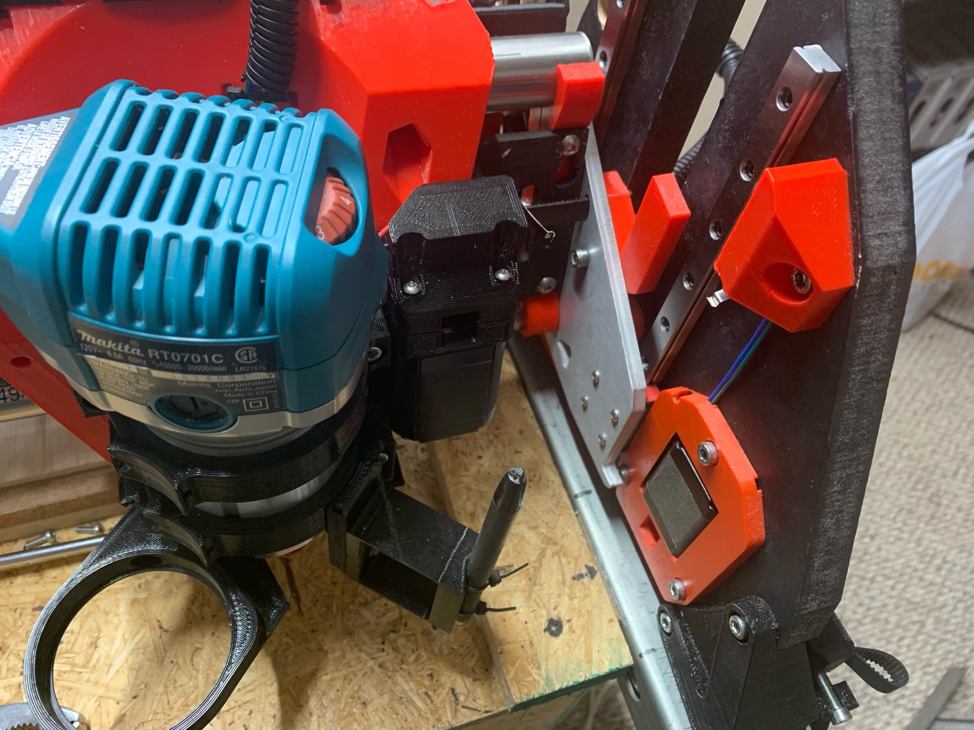
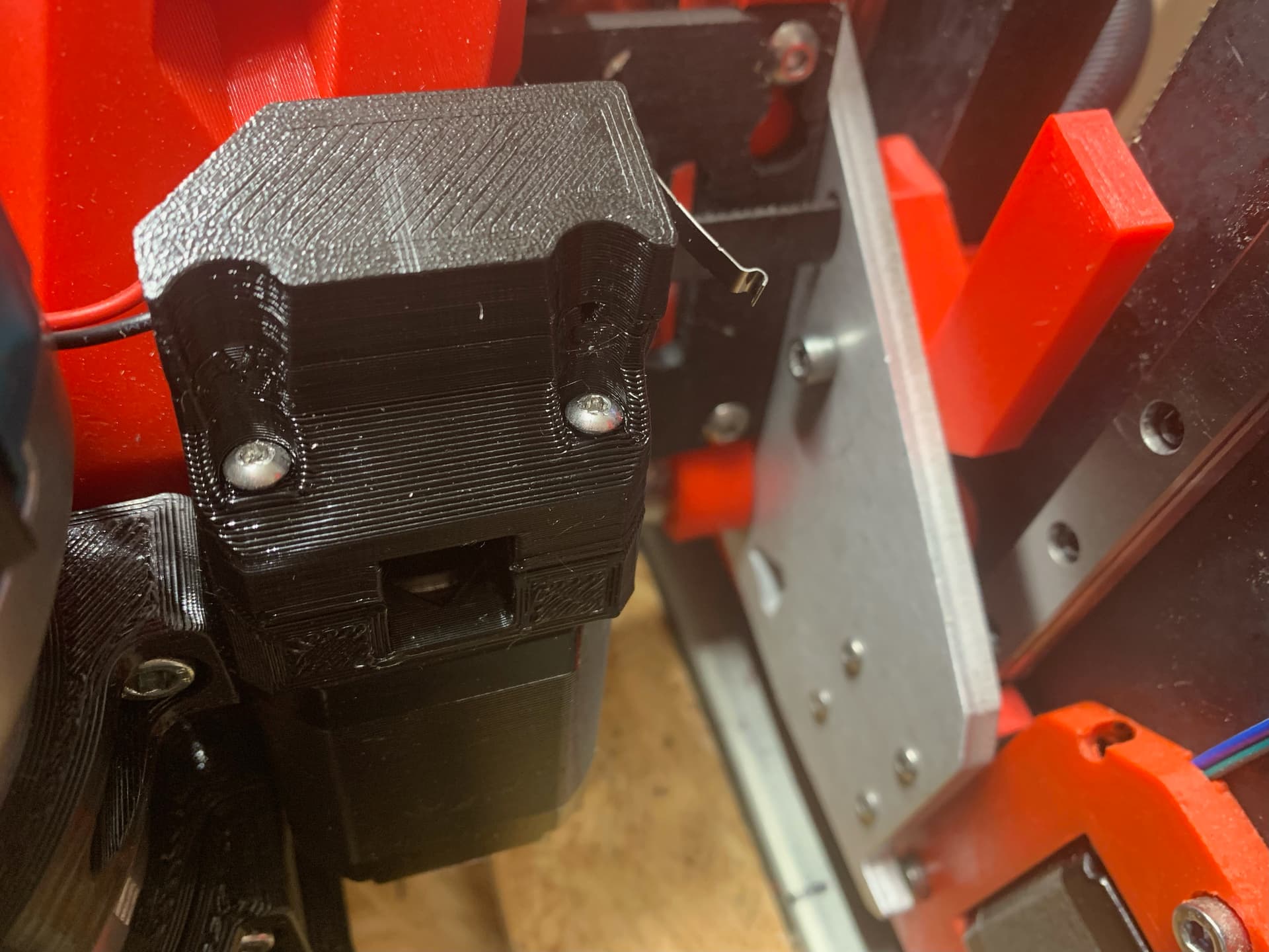
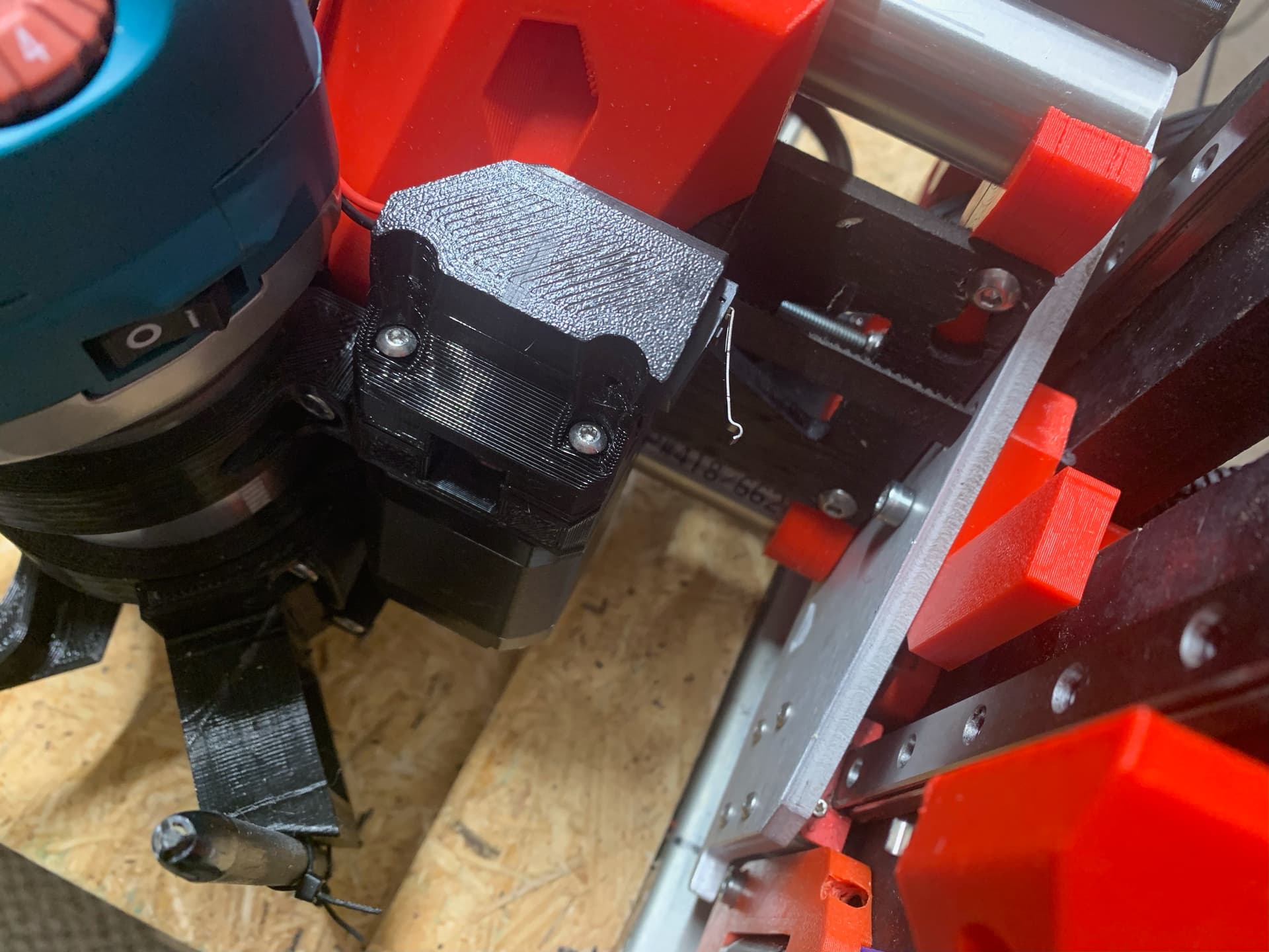
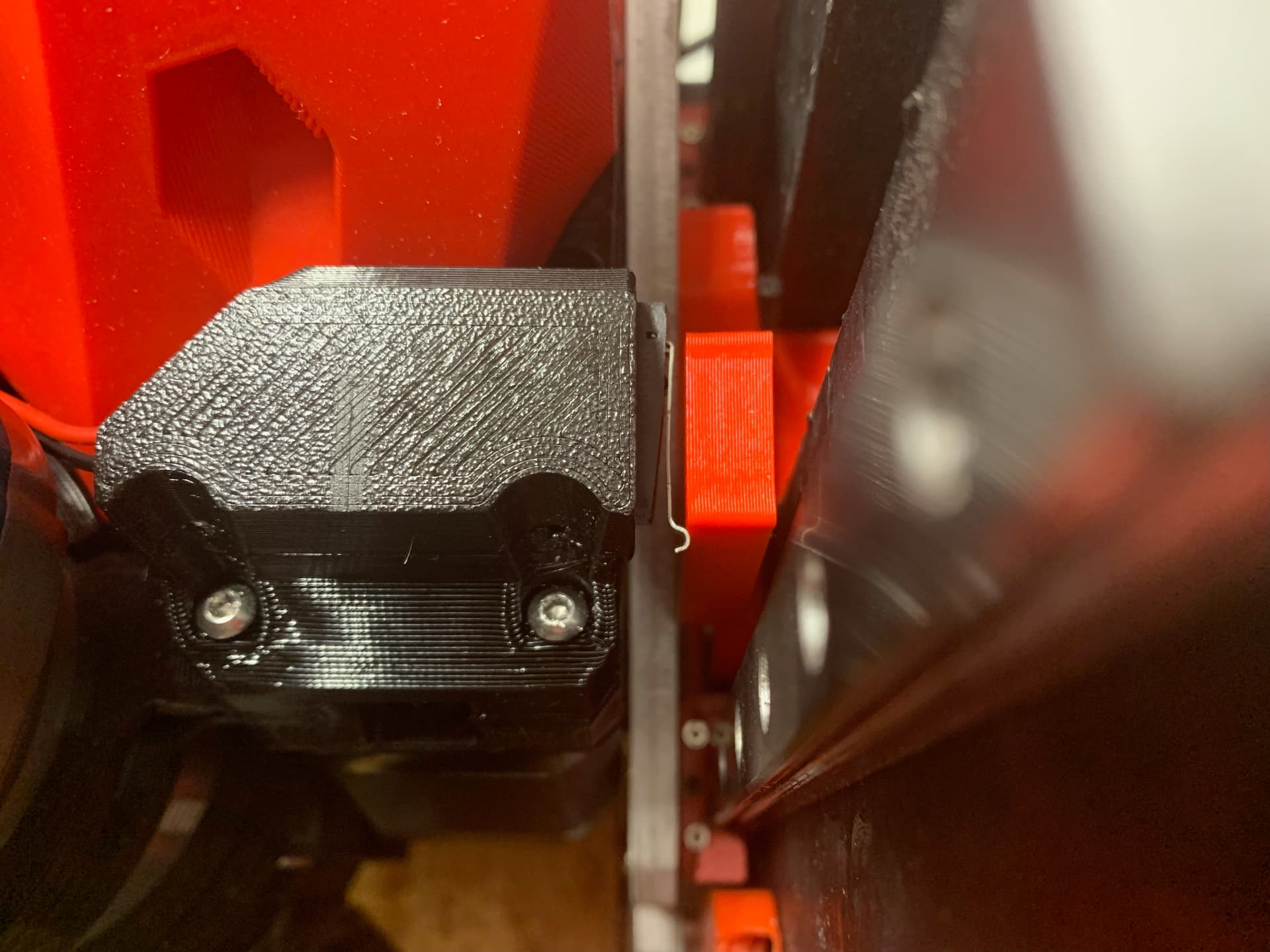
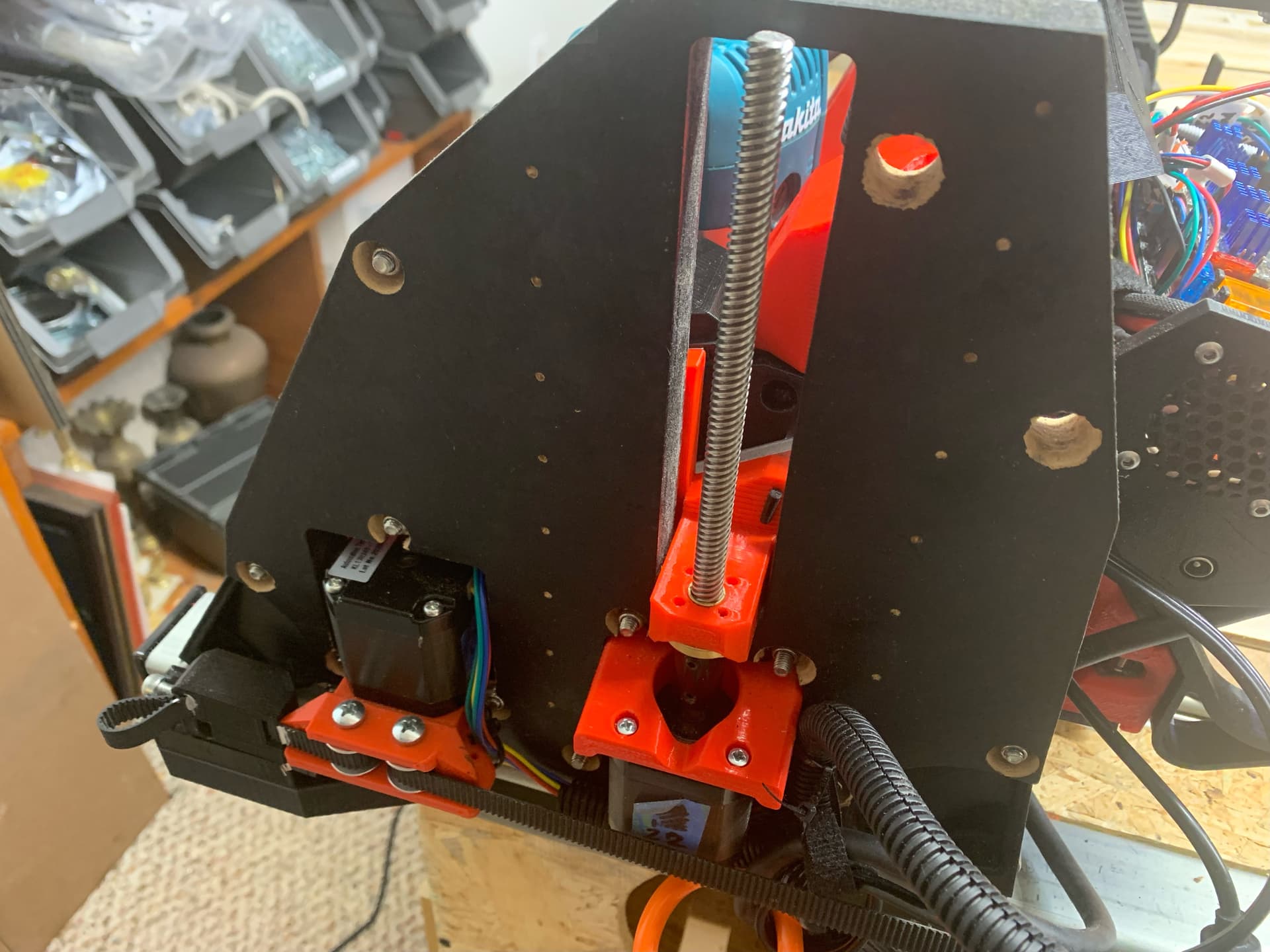
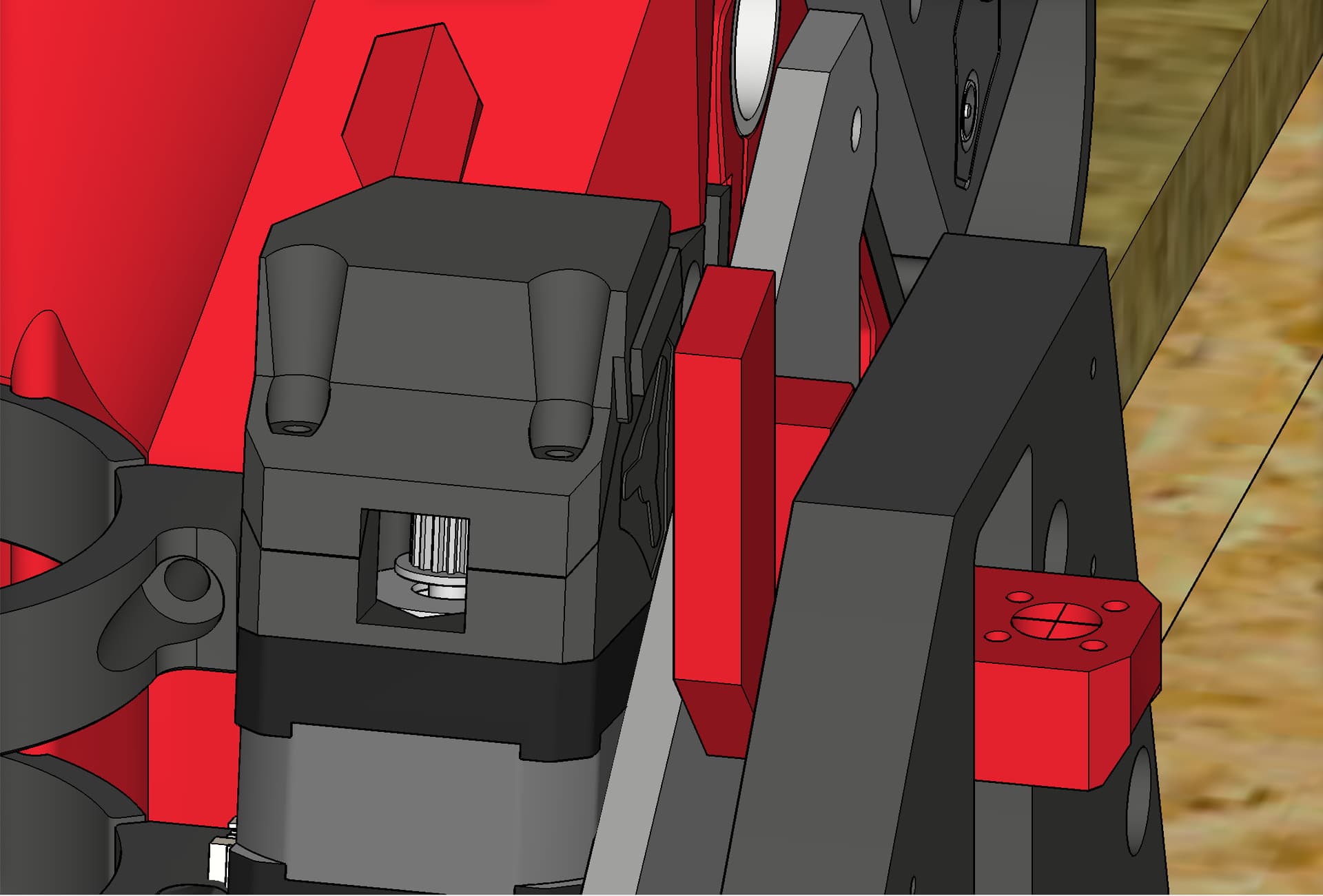
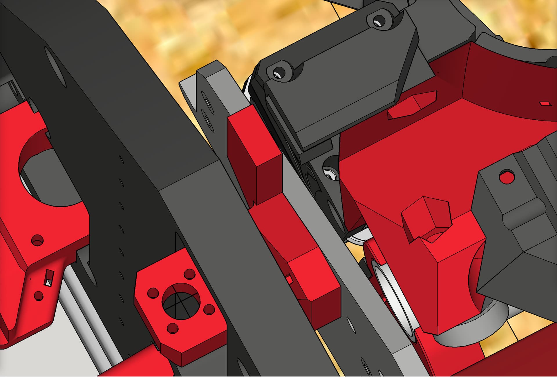
- I moved the former X end stop switch (which is becoming the new Y end stop switch) from the left side of the LR Core to the right side of the core, attaching it to a newly designed & printed end stop mount that attaches to the former X stepper motor mount, which is becoming the new Y stepper mount. I also re-ran its wiring accordingly.
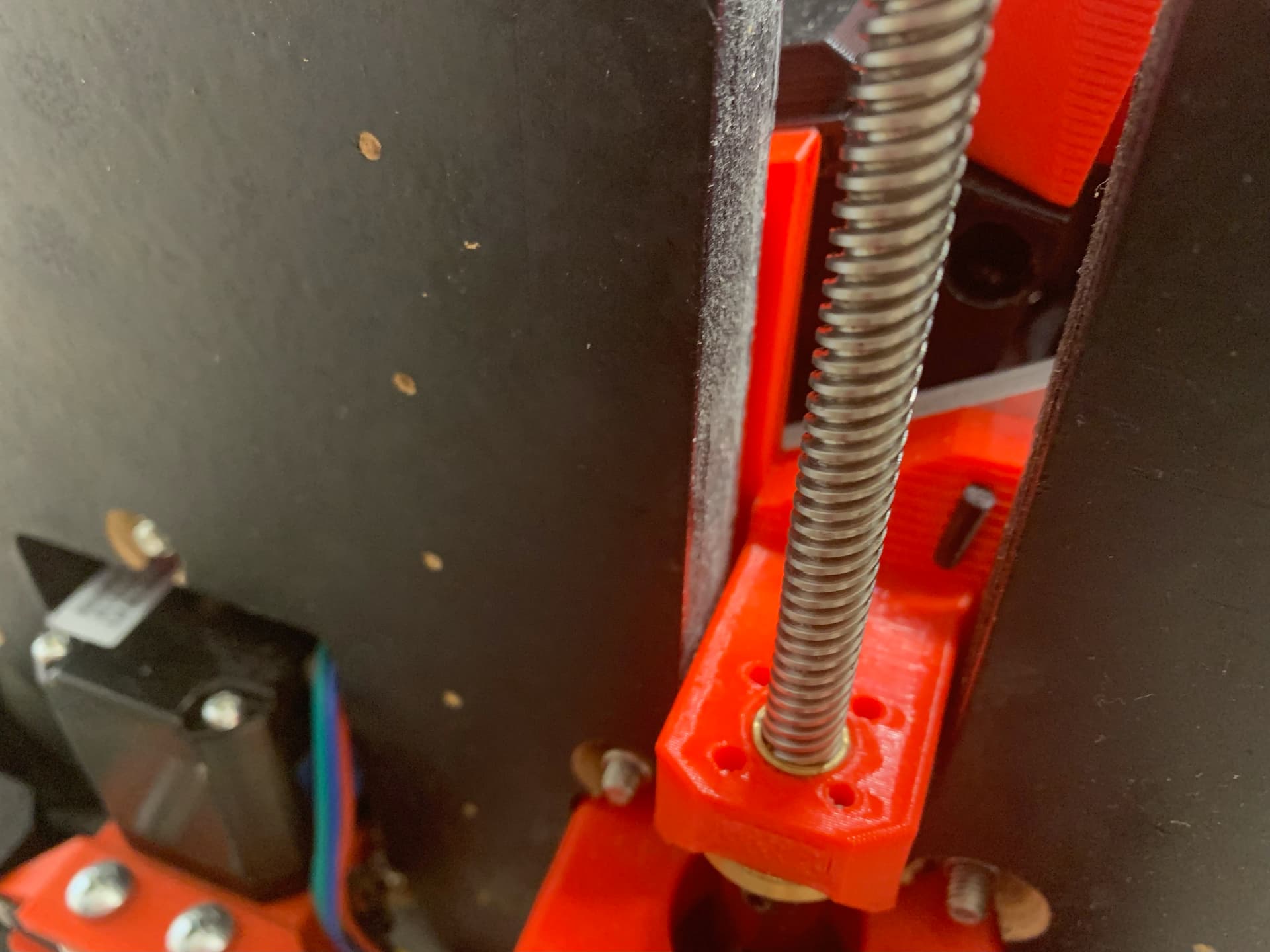
- I designed, printed, and installed a newly remixed “stub” on the right side of the old X axis (new Y axis, on the new Y-min side). The only change was to add a “stop” bar for the relocated X end stop (new Y end stop) to press against and trigger its switch. This stub is the part that the X belt (new Y belt) attaches to, and which also attaches to the lead screw on that side.
- In control box, I swapped the wires for X1 driver and Y1 driver with each other and re-labeled accordingly.
- In control box, I swapped the wires for X1 end stop and Y1 end stop with each other and re-labeled accordingly.
- In control box, I re-labeled the Y2 end stop as the new X2 end stop while leaving it plugged into the same pins, at E1 (on the SKR Pro 1.2).
Note: Some of what needed done could have been accomplished more than one way, such as firmware changes only, or physical rewiring only, and where I could, I chose to physically move wires and relabel them. This limited the number of needed firmware searching and edits.
Q. No ‘mirrored’ projects? You didn’t have to remap the coordinate system?
A. Correct. It works exactly as intended and expected, without any need for ‘mirroring’ projects or remapping of coordinates.
Check out a few seconds of video showing that no mirroring or other headaches are needed:

DOWNLOAD PRINTED PARTS
https://www.printables.com/model/229940-lowrider-3-cnc-reversal-of-homing-on-short-axis-fo
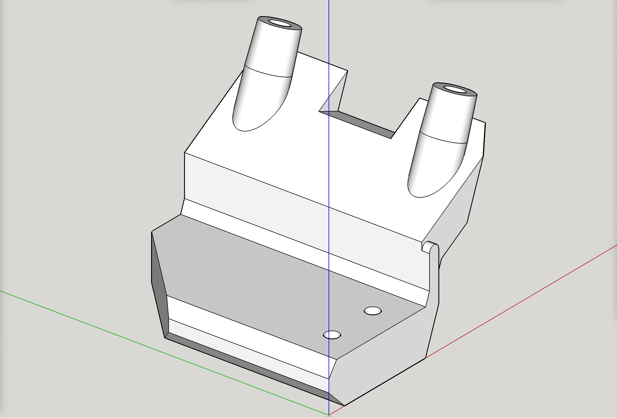
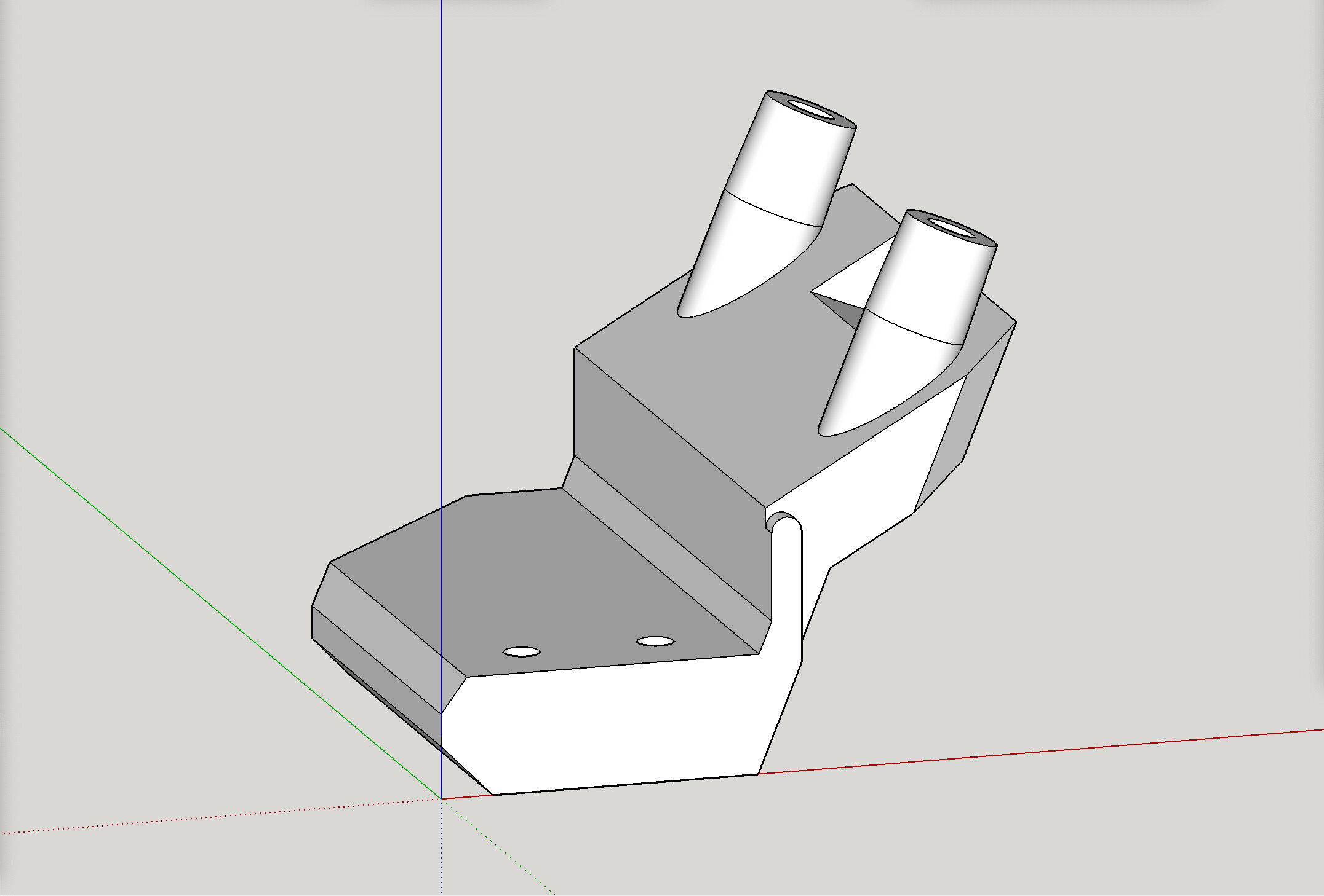
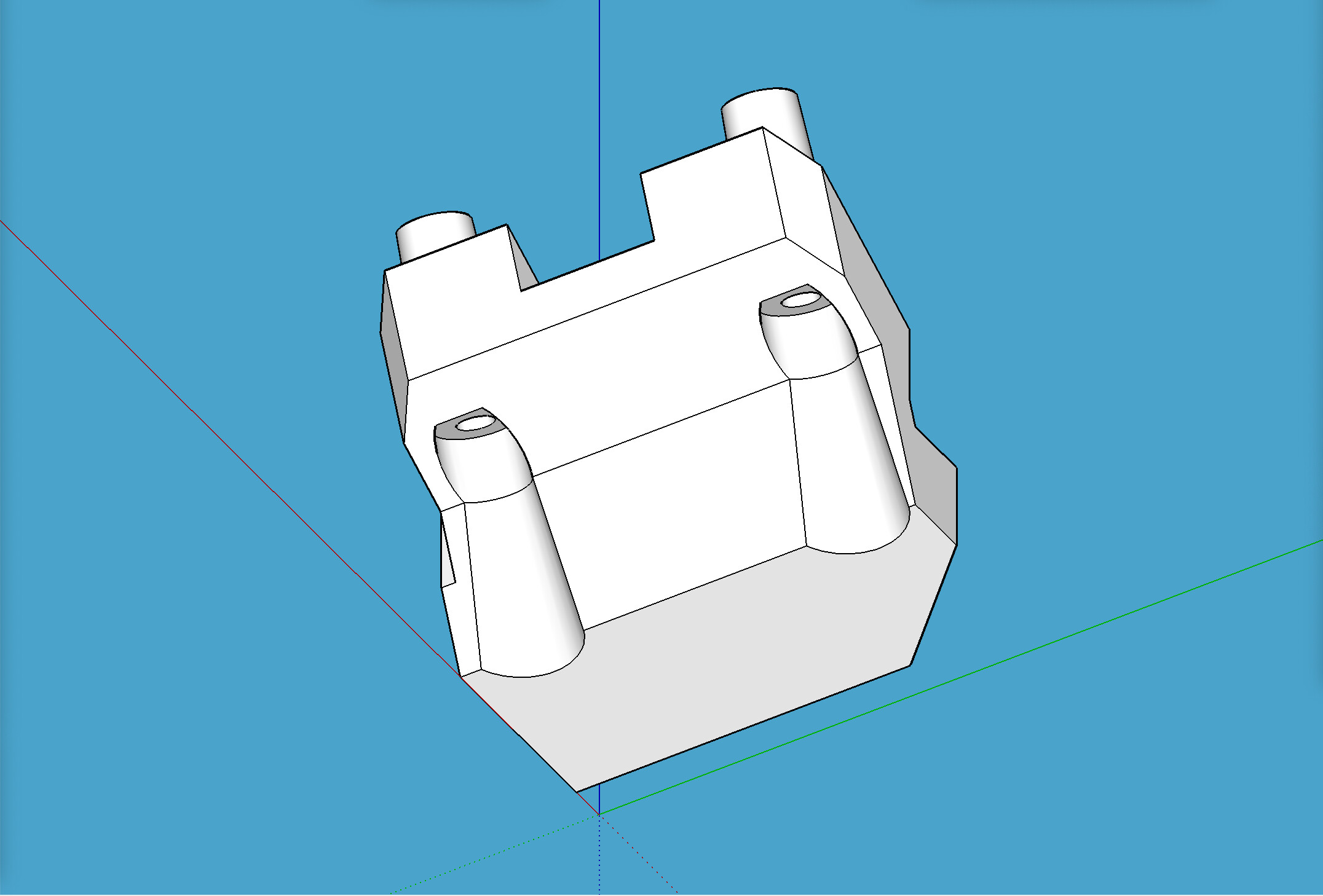
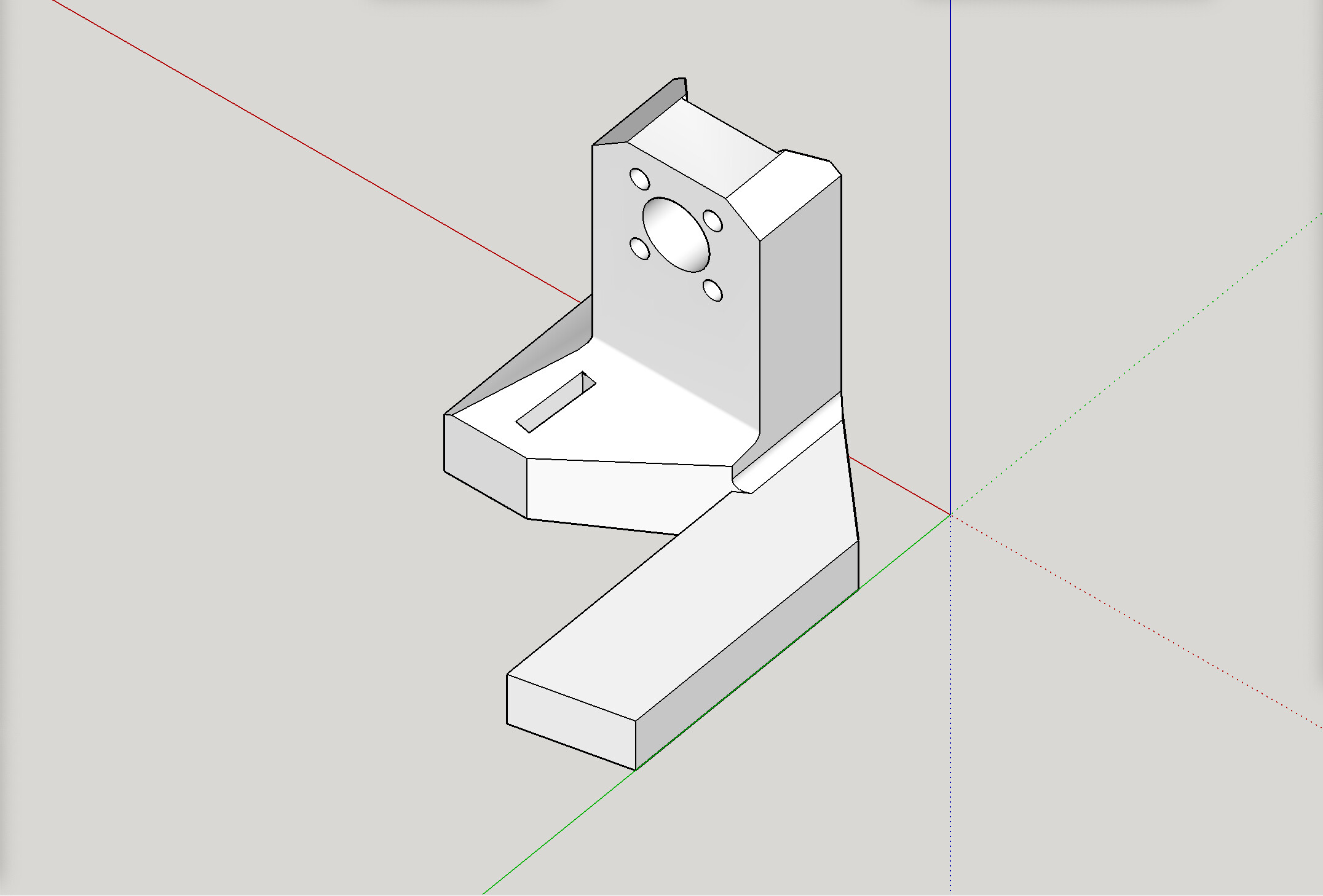
Aside from moving the end stop, it was as simple as adding on a “tab” onto the stub-right, for the end stop switch to touch for triggering. Here’s a pic of the modified stub. More pics below.
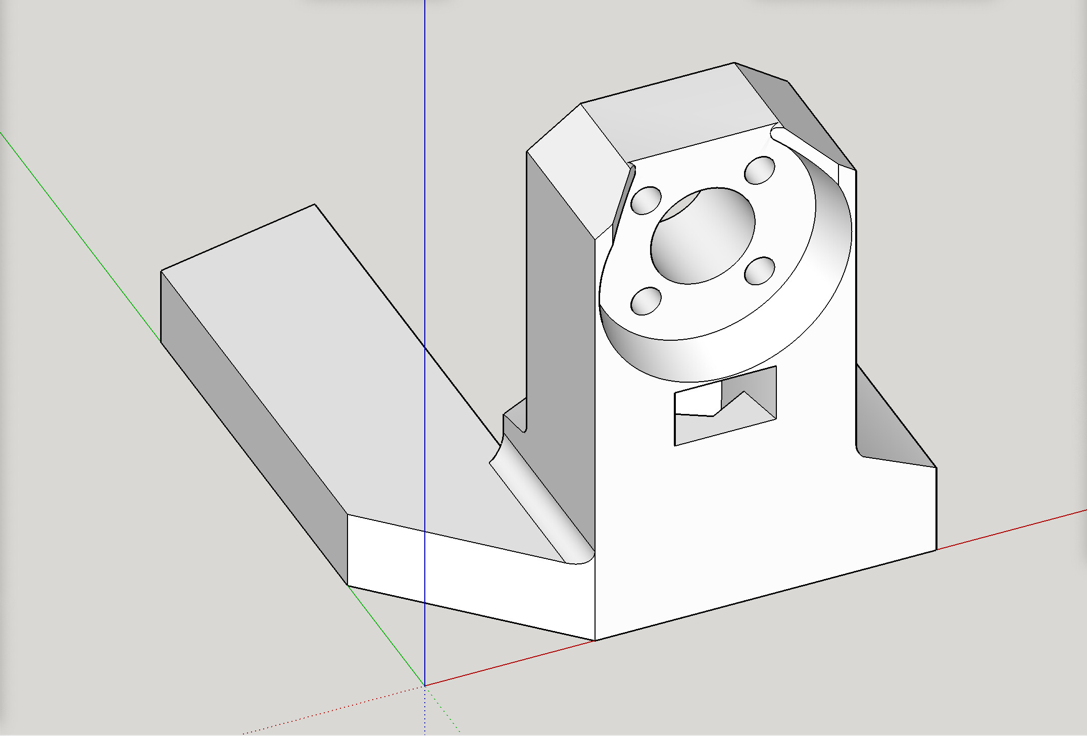
Why add it to the stub?
The stopping point for the switch to touch, has to be “part” of the whole assembly that raises and lowers with the beam itself. It’s likely unworkable to try to use the YZ plate’s flat side as the stop point, as you’d likely see the end stop switch get higher than the side plate itself while the beam is Z-homed to the top max, and then snap off your switch’s trigger finger when then moving back downward.
Here are some pics, including some of the modified stub:
2 Likes
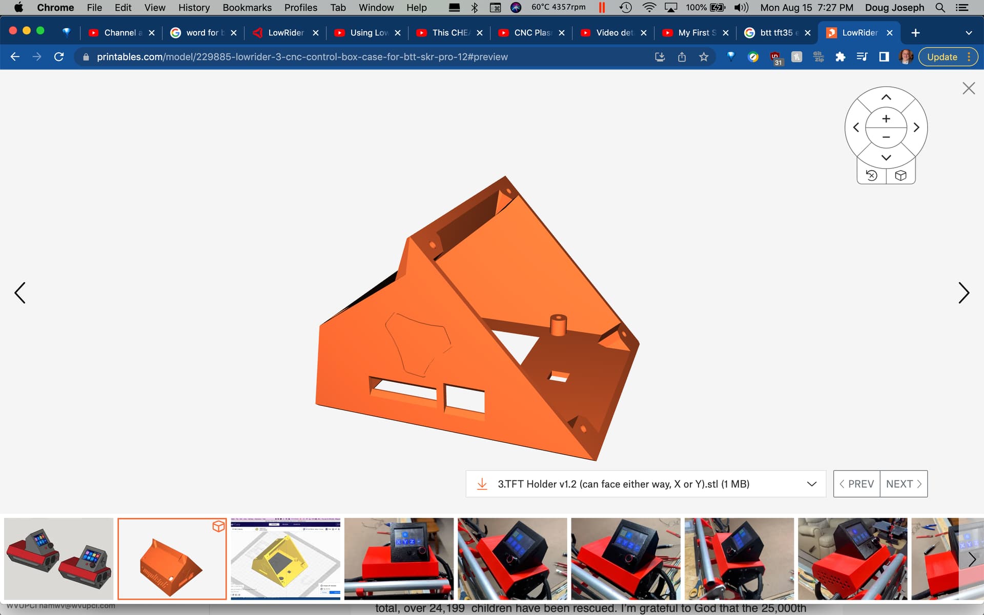
OK, good news. I have now added USB port opening in the E3 version of the TFT holder v1.2.
https://www.printables.com/model/229885-lowrider-3-cnc-control-box-case-for-btt-skr-pro-12
2 Likes
Hi there Doug
Your build is looking great!
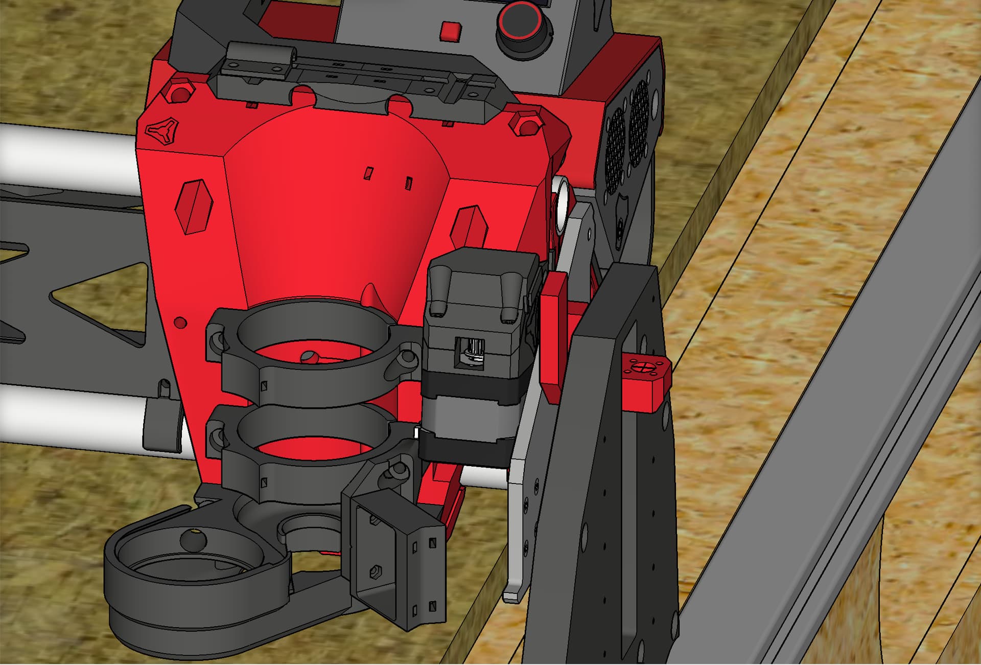
I used your remixes shoe and hangers for 2.5” hose, but my particular routing and machine location is causing issues with the regular hose routing path.
I’m planning to mount an overhead boom arm and suspend my hose- I believe you do this also? Any chance you have some pics you could share of that aspect?
Thanks so much!