I took 3 new videos to try and show as much as i could. I uploaded them to the fb group
In an attempt to keep everything here for future knowledge base, and to make it easier to find…
5 mini-videos smashed together into one. I think I found the problem, and now I just need to work on the solution (mentioned in the next post)
here is the second version of my youtube video

I think I found it. I ran $Limits to test if the signal was actually getting to the brains. X and Y0 both reported when being triggered. Z0 never reported anything.
At this point I am thinking that maybe I go into the config and tell it to use the empty io pin and then swap from 32 to 39. I have (in my nid anyway) ruled out the firmware, config, driver, and wiring. The only think I can think of is that for some reason IO32 is triggering the light but not actually sending the signal. I’m at a complete loss on this one. I could just swap the board, but I dont think that is the answer at this point unless I was trying to use all of the IO pins for other switches and stuff.
This will show if you…
it doesnt stop. Thats been the issue from the beginning.
I updated my video which means I need a new link. I’ll edit that post and update once Youtube is done taking its sweet time.
**** new video is loaded. post has been updated.
Interesting.
So that could actually be the esp32 with a bad pin, the inputs are one to one wired to an esp32 pin.
On the bad input if nothing is plugged in to the port is there a super faint linput light? Trying to figure out if it is the esp or the jackpot.
This sounds like the same issue I had with one of mine but on the probe pin. Difference is the light would not even flash when the probe was triggered for mine. His the light is changing but the ESP isn’t seeing the change. For mine I had to move it to the spare endstop port to fix the probe.
Just trying to be clear on the process here.
Unplug the endstop from gpio32, power up and turns out the lights. Look for light on io32?
What pins on the esp would be the right ones to take continuity checks?
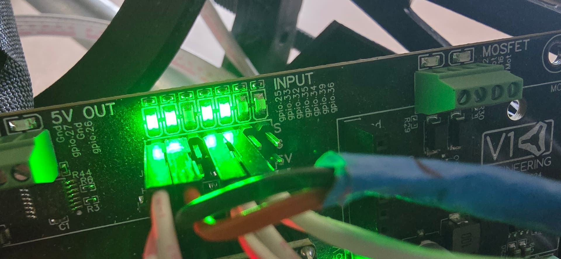
Really hard to tell but looks like maybe a faint light
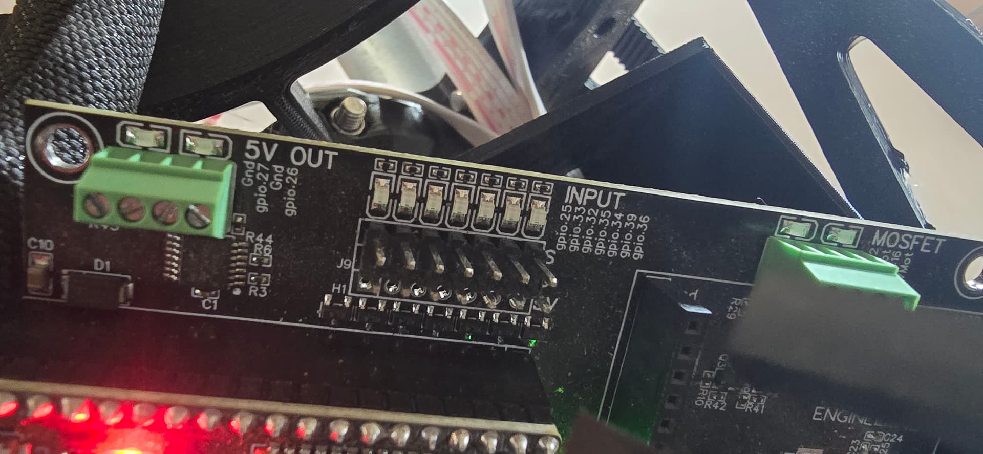
Unplugged the rest to see it better and i don’t think there is any light
That seems like an ESP32 issue then, really odd. Any chance that something weird got plugged in for a second to that port or some static discharge? We have never seen this issue before, other than an accident.
Easy enough to just change the config either way to use the empty port.
No chance of anything getting plugged in. Static is possible, it’s not like i wear my little esd wrist band and smok etc. Most likely cause of unknown voltage is back feed from the motors. The machine falls when the motors aren’t powered and i have seen it light the leds.
So i just need to go into the config and change gpio32 to gpio39 and move the plug to the spare port?
this is where the gpio.32 used to be.
motor0:
limit_neg_pin: NO_PIN
limit_pos_pin: gpio.39:high
Now I just need to try it and see what happens
1 Like
IT WORKS!!! Homed all 3 axis, moved out to 1150,2400,-70, then homed all 3 again.
2 Likes
That doesn’t affect the inputs.
Be interesting to know if there’s continuity on the traces from the non working input to the esp32 headers. Or if a different esp32 worked.
Bit glad you solved the issue regardless.
2 Likes
Sounds like what I had with an mpcnc i bought assembled.
The problem was the builder used Dupont pins/housings to connect the limit switches to the control PCB. Problem was the control PCB expected JST pins/housings.
The Dupont pins are 0.25" square post. The JST pins are thinner. Both use 0.1" pin to pin spacing so the dupont female housing/pins plugged onto the control board but the smaller male pins on the controller didn’t make good contact with the limit switch. One side worked while the other didn’t. Hope this helps.
Uh, probably doesn’t. If you are moving the motors with the drivers disabled and generate enough voltage to back power and light up an LED, you don’t really know what ESD diodes or other components are providing sneak paths for current to flow. Nor what that might hurt in the electronics.
Blowing up the board with manual/ unpowered stepper machine motion is rare, but NOT impossible and we’ve seen a few like this recently. Blowing a pin with ESD is also a real possibility.
There shouldn’t be straight continuity. Those inputs are at least mildly hardened with a diode, have a 50 ohm series resistance and a moderately sized (10K) pullup ahead of the GPIO.
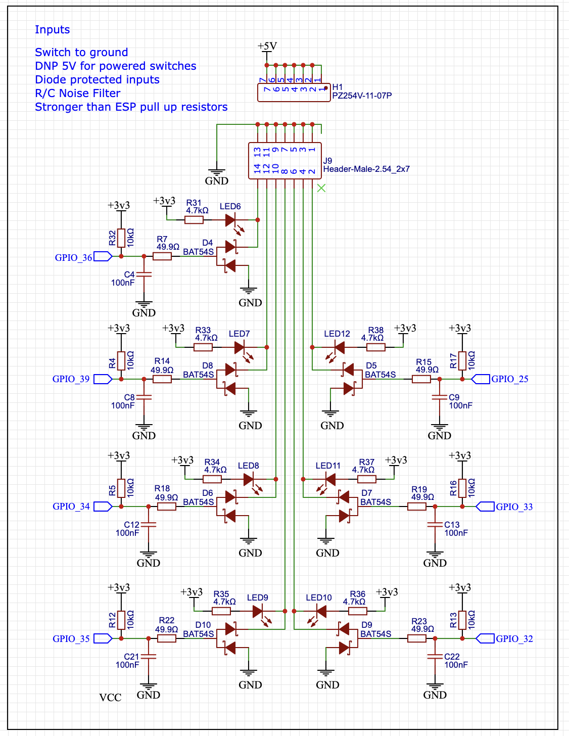
Edit: Yes, I would be interested to know what is measured for the bad (and good) input pins back to their ESP-32 Pins on this particular board.
After i cut my strut plates and have to run all the wiring and mount my stuff to the strut, I’ll take measurements.
If you have a list of things you’d like to see tested I’ll check. But I’m not well versed in what pin goes where. So if for instance you want to know pin 6 on the esp to pin 2 on the io port, I’ll need that level of information. I can take voltage drops too as that is likely a better measurement than just resistance. I just need to be spoon fed locations because i don’t know what goes where on this board.
1 Like