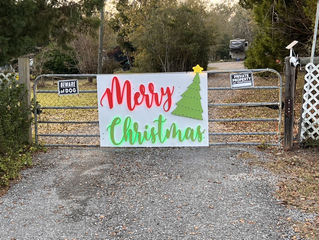
Putting it together was a nightmare between having stand offs and getting all the LEDs routed and attached. I have a few people that want one for their property so Im hoping i can figure out how to make assembly easier this time around.
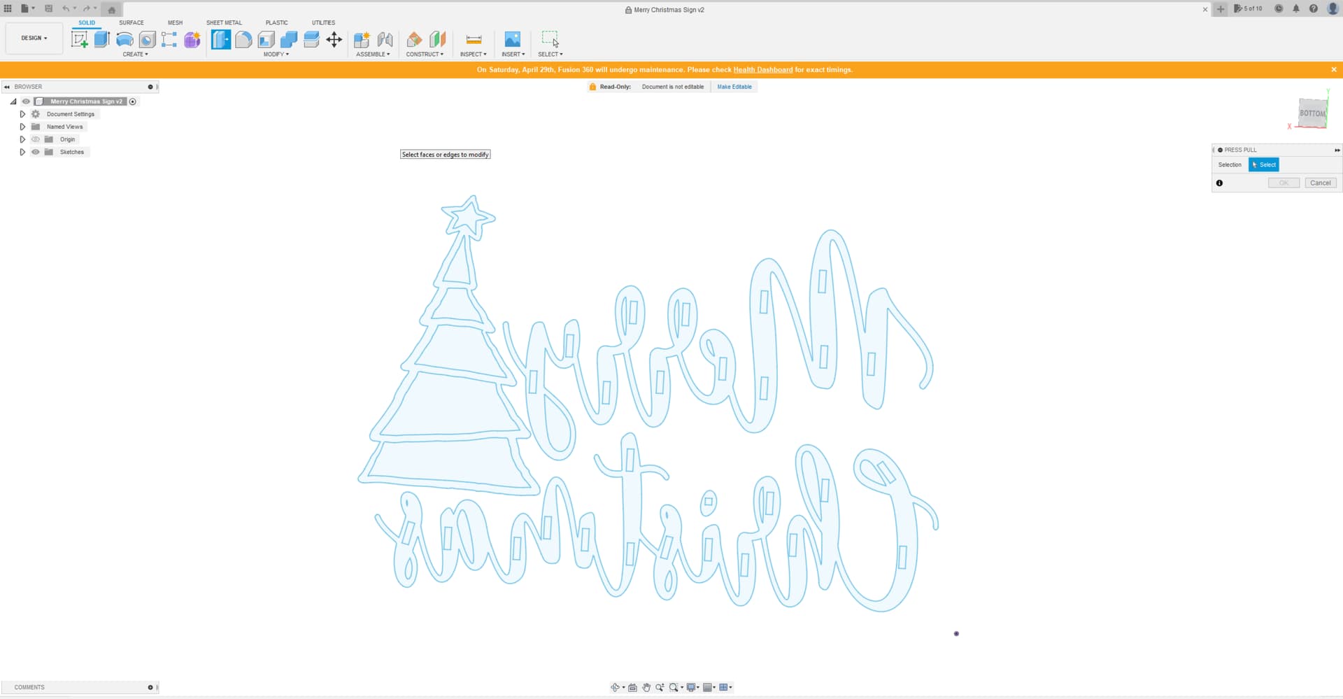
What im hoping to do is to import the SVG i have of the sign. Get it all arranged how i want it. Then be able to put some kind of groove around that i can then mill in for all of the LEDs. I would also like to place and make a cut out or something for all of the stand offs as well. Anything i can do to make the assembly easier LOL. Last time i laid out the words and got them all situated how i wanted them then took a marker and traced aroud them. Then took some 3/4" x 3/4" roughly 1 1/2" long and attached them to the base. I had to take special care not to run the LEDs where a stand off was when i was attaching them to the back side of the words.
Is there any way to easily take and make a 1/4" grove in fusion that will follow the path of the letters? then i can go in and manually add the stand offs. I have searched and searched google and youtube and i cant come up with anything like what im trying to do. Im sure im just not asking the right questions. Hoping you fine folks here will be able to understand what im trying to do better and be able to point me in the right direction. Any help with this would be awesome! Trying to get a jump on Christmas orders early this year and of all the ones i have to do this one Im dreading the most so may as well start with it. Only dreading because i know what i went though last year making mine LOL. Thanks in advance for ANY help!!!
Anyone have any ideas? Im half way tempted to just set estlcam as a large bit and have it cut out another run that will be smaller and use that as the standoffs and put the LEDs on the sides. My only downside is that in the spots where the words are thin i wont have any lighting there.
I somehow missed your question when you originally posted it. I look at the forum posts sorted by “Latest.” Once in a while, I see a post I “missed” and suspect that somehow the time was “wrong” on the post, and it was sorted below the “Latest” posts.
As for your question, I’m unclear about your specific issue. You mention “fusion” in one place and “estlcam” in another. Are you authoring your curves in Fusion 360 and then exporting the DXF for use in Estlcam?
In Fusion 360 you can right click on text and then select “Explode Text.” This will convert a text object to paths/curves. The curves will be “Fixed” so you will need to select the curves and do a Fix/Unfix if you want to edit them. Text objects can be copied from one sketch to another if you want to preserve the original text but have a curved one that you can manipulate. Unfortunately, offsetting these curves as a whole likely won’t work (hang Fusion 360). Fusion does not handle complex curves very well (likely due to Fusion’s support for constraints). In addition, offsetting curves that cross will generate “clipped” paths, so that is probably not what you want.
If I understand your problem correctly, this is what I would do:
Author your sign, to scale, in a Fusion 360 sketch. This sketch can be used as paths to cut out the lettering and decoration.
Start a new sketch on the same sketch plane as the original sketch.
Project the outside boarder of the sign to the new sketch (for alignment)
Author a fit point spline that represents the centerline of the lights. The Fusion 360 spline tool can be a bit frustrating when you first start out, but works well with a bit of practice. It has a few “hidden” features like the ability to add additional points after the line is drawn.
Author the outline of the standoffs (slightly smaller than the real standoffs). Note you can use the measure tool to verify that you’ve left enough space between the lights and the standoffs. Assuming you are using strip lights, the distance should be more than 1/2 the width of the lights.
Optionally add the bore holes (or at least marker lines) for the wires to come through the back board.
Export this new sketch as a DXF (assuming you are using Estlcam for the CAM).
Do a shallow cut with a small bit on the back board using the exported DXF.
What kind of lights did you use? Are you using 10mm LED strips or Christmas lights or…? If using strips, how did you handle the places where letters cross over themselves?
As I re-read your question, I’m trying to understand the problem. You show the position of the standoffs in your Fusion 360 file. Are you milling the outline of these standoffs on the back of the words? If you are not currently milling the standoff outlines, would doing so give you enough information to string your lights around the standoffs?
From a Fusion 360 perspective, in 5 or 10 minutes per word, I can hand draw a fit point spline down the middle of the writing. That spline can then be used to cut a groove.
When originally made I just cut the words out. No standoffs or grove. Which was a royal PAIN. Hoping by cutting the grove i and save my self a lot of headache. Here are the LEDs i plan to use…
The groove is not just above placement. You want the groove as a physical way of mounting the lights.
You want your lights to outline the outside of the text and graphics.
You have a router bit that is the width of the channel you want to cut
You are using Estlcam for the CAM
I’m not an Estlcam user, but looking at the tool tips, an “Engraving” toolpath set up to cut either to the left or right of the path should do the job. From a graphics point of view, all you need is a path that is a bit inside the outline of text and graphics.
On my desktop machine while editing the sketch in your Fusion 360 file, I was able to double click to select the outline of the text or graphics and create an offset (Modify/Offset). Fusion 360 had to think for a bit (probably close to a minute for the “Christmas” text), but in the end, it allowed me to create the offset line.
Fusion 360 struggles with complex paths…probably because it is calculating constraints and intersections. If Fusion 360 fails at the task, Lightburn will do it easily. Lightburn is not free, but it is also not a subscription. If you don’t pay the yearly fee, you don’t get upgrades, but your tool continues to function, so you can treat it as a one-time purchase.
Hack Alert: Here is something that might work. You might be able to fool Estlcam so that it does the work for you. You could use the outline of the text as the reference for the toolpath, setup to cut inside the path, then set the bit diameter larger than the actual bit. For example, if you were going to cut a 1/4" groove, and you specified, in Estlcam, the bit as 3/4" instead, Estlcam should cut the groove 1/4" inside your text.
You assume mostly correct. I have to measure the LEDs again and see if they will fit in a 1/4" groove. If not by using the offset line you created in fusion i should be able to engrave on the line and then again next to the line and get the width I need.
I also had thought about doing the bit larger for the offset. But if its capable of making the offset line in fusion I think that’s the better way. I was sure it was able to do it I just didn’t know how and didn’t know the right thing to put in google to find it LOL.
Thank you for the help!! I’m going to mess with it in fusion and see if I can get it to make the offset line like you did.