I think it is done!!!
The last pieces are getting fillets and heading to the printer. I really hope they work because I only have a spare 3-4 mm if it doesn’t work.
I think it is done!!!
The last pieces are getting fillets and heading to the printer. I really hope they work because I only have a spare 3-4 mm if it doesn’t work.
I’ve been subtly dropping hints with my wife about a sand table for about 6 months now. About how much do you think the electronics/parts and such will end up being (not the things like wood, glass, sand, etc… just the V1 engineering stuff)… roughly speaking?
The controller, two motors, two endstops, wires, a magnet, a power supply (which can be wimpy).
Hardware will add some. Bolts, tubes, bearings, idlers and pulleys.
There are lots of ways to save money on it (I used a 12V 1A PSU from an old router). The controller is the big ticket item. After that, the table will dwarf the cost, unless you can get one used.
I am going to say conservatively, $200, but probably less. But with your other hobbies, you might away for nearly free.
Doesn’t sound bad… yeah, table will be the challenge in order to convince the wife to put it in the living room.
Well maybe if this comes out well and a few of us build some nice ones we can help convince her for you. I can say it is one of the projects that I have done that gets the most attention. I have done all sorts of things large and small and that is the one that gets mentioned…go figure.
I think I have to show her I can build something of ‘quality’ for the living room. She’s not into plywood furniture. So maybe I can find a coffee table she likes use it to build a sand table.
You have a mobile robot roaming your house. This should be a no brainer. 
You could always start building it for the office and then, if it works great, suggest keeping it in the living room “for a while”.
Lol… she hasn’t allowed Floyd downstairs yet. I still need to do the skin for it and figure out the docking (think I’m going back try out the traditional docking method of rolling onto a platform with contacts)… the docking arm mechanism has been too unreliable after all the components (wires, etc.) are added to it.
But to your point… I could get her to pick out a coffee table with a glass top from wayfair and assemble it upstairs and then quickly and discretely build the sand table into it and say “what? Isn’t this what you ordered?”
Ohhhhhh I have been busy doing all sorts of small tweaks. Feels like the most intricate, detailed thing I have designed yet.
I have it fully assembled, now I have to figure out how to add it to my table without taking the powder out.
I’ve been using a mechanic’s creeper to work under my table. After so many years working under a car, it seemed like the thing to do. It was so much easier to work on before I added the sand, almost makes me wish that I’d left a way to drop the sand portion out to work on the mechanism.
Okay built…bummed it was not perfect on my first attempt…back to CAD…happy but I have one last issue that I need some voices on.
The magnet.
I have it in a round hole and a screw under it to adjust it. If I go back to just a hole and shims the build would be centered and ideal.
I know some of you are not using the exact magnet I am so the hole would be problematic for some of you anyway as it is more constrained (I do plan on carrying them in the shop for easier access). So if you all have access to the solid files you could easily edit the part to fit your magnets, and shim to fit your build.
The screw is easy but forces and asymmetric work area. Shims are kind of a bummer once…but you never touch them again. This would allow for symmetry and a larger overall centered useful area. Symmetry just means an easier build…calculator, and instructions.
So I think I am going for the shims like it has been. Although I do believe it will be easier this time due to a much more constrained system, so measurements are far more exact and stable. The current zen can shift and cause the magnet to hit. The new one can not.
Well I just think I talked myself into it. I wanted adjustments because it moved before. Now that is does not so they are not really needed.
I would go with the shims, and then add a 3d printed shim model. 
A 3D printed shim (even if it is literally a cylinder) would be able to be scaled in the slicer to fit. But even without that, there are washers or spacer models or just scrap paper or plastic.
I was just drawing this up yesterday.
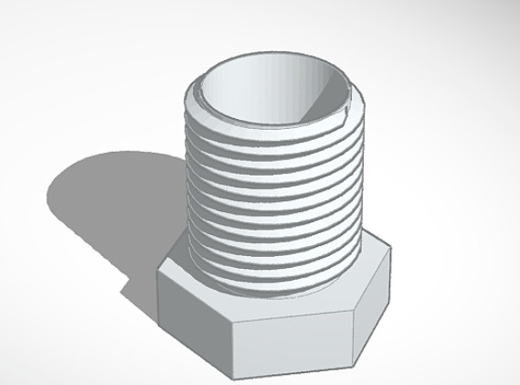
I went with something a little different. A “bolt” slightly oversize for my magnets (1/2" diameter) 3D printed, and fit into a threaded hole. I chose 5/8"-18 as the basic thread for this. I planned to clean up the threads (and the threads in the center shuttle) with a tap and die set, because I happen to have them.
This gets around the offset angle of the screw, because the whole assembly is centered. It also allows for adjustment at any time, or fixing it permanently by staking it or melting in the threads. It’s easily adjustable for different magnet diameters, shapes or lengths, if you do any design stuff at all. The tricky part is having the tap and die set, but with a good enough printer you shouldn’t even need that.
All that said, I’m probably overthinking it because my magnets are a set of discs instead of one piece, and just sucking it up and paying for the shipping is probably a reasonable solution.
Yeah so I can add a mag shim, easily Z scaled. I used a nut and paper on the previous one.
I do plan on supplying shims for the corners since this version is lower profile, ~4mm clearance. So They can be Z scaled as well. Supply them 1mm thick so the math is easy.
I will try to CAD it up and test it after the boxes today. I don’t have any fasteners on the magnet though so that could be an issue. I will see if I can sneak a screw in even if it is just to stick to. Hard to describe how tight everything is to make it fit the old footprint.
TLTR I think I got it. I have to print out a full set of parts and rebuild it to test. 0.5mm to spare.
I spent some time this morning and tonight in CAD.
I have a new idea. I kept the screw adjusted magnet not 100% sure it will work, so I need to print it. The screw is at the edge of the magnet, so it might push it funny, but I doubt it because it will stick to the screw.
The build is asymmetric but to offset that I am just going to add some small offsets so it will align with a perfect square. And easy enough to cut off in CAD with the Step files if you really want to have max area. It is off (asymetric) by 1.65mm on the X axis and 29.8mm on the Y axis.
With that said it fits in the previous build with 0.5mm to spare on the X and a lot on the Y~34mm (x2). So it actually has a rectangular build area that is why I will add the offsets.
That will make a lot more sense when I let you at the files I am sure.
Okay, now I’m champing at the bit here. I want to get started!
I’m hoping that I have the hardware, you mentioned small nylon wheels, which I’m sure that I do not have, and different sized conduit (Which I’m sure that I can pick up on short notice.)
I might end up without the sand table portion when I test build, just put it on a sheet of plywood to try the motion out, since my second LACK coffee table is being hacked to bits for my testing. Well, come to that, I can probably just make something as a sand table relatively quickly, too.
They are 15.23mm v groove wheels, I am waiting on a bulk order but these are them. https://amzn.to/2ZAxPNb Looks like 17 are needed.
Putting it together right now.
Ok, I ordered 20 of those wheels, another 2560 based control board for now, some more idlers and belt.
I suspect that I’ll need some more nuts and bolts and the conduit, but those should all be available somewhat more easily.