Zip ties might be one of the non-IR opaque plastics. I think I tried using them as flags. Might depend on what color…
I was triggering with a zip tie on my printer for a while, until I moved to one of those aluminum zip tie things with the adhesive backing.
“natural” nylon isn’t really apropriate, but black (or as I tested, red) is okay. YMMV
I like the trimmable aluminum idea, it’s pretty much what I’m using for my table now.
Finally, sat down and really took a look at everything. I like it. Two tiny changes. I am going to extend each trigger 1mm, super quick tweak. The other thing is adding a couple wire anchor points on the motor mount blocks. The wires are super close on the X trigger so it is necessary.
Besides that this homing sequence works swell.
G28 Y F1800
G01 Y-2.5 F600
G92 Y0
G28 X F1800
G01 X-12 F600
G92 X0
So as soon as I CAD that up it will be a RC release (meaning parts will be available but instructions and stuff will be slowly added). Hopefully we get a few more builds happening to really test these new parts out.
Shipping and hardware is really slow and sketchy again so I am having to spend a lot of time dealing with all of that to try and keep some product on the shelf. So I have some Zen parts but will not have a full kit for at least a month maybe even two.
Looking forward to the RC release, looks like I’m going to need to find those endstops, since they’re different from mine.
I ordered a bunch of them with different wires but they are not here yet. I think I have two more of these though, you just need to shuffle the pins on the plug side. I will check and send them out if I do.
Pretty sure the CAD is done. I broke some mates so I am updating the assembly just to be sure.
I found the same opto endstops, but 3 weeks to ship 
I’m going to try to play with the ones I have, since now I have way more than I’m going to need for the forseeable future, even if I change all my 3D printer stops over. I’m going to try to move the wire harness to the same side as the endstop. I might have to do that with regular pin headers instead of the ones it has though.
Edit: Even if I do change that, the mounting holes probably won’t line up, since those have the mounting holes outside the wiring harness location, so I might have only 1 screw holding each endstop. I can probably make do with hot glue or something. It’s not optimal, but I think it’ll work okay.
Oooh. But the parts are too red. They should be black and full of glitter!
I already shipped you some.
I spent all day trying to set up a cluster for rendering…yeeesh

Are we still using conduit?
Yeah. That looks good. Reminds me of q storm trooper.
Yes. 3/4" and some 1/2". With the plastic wheels it is super quiet.
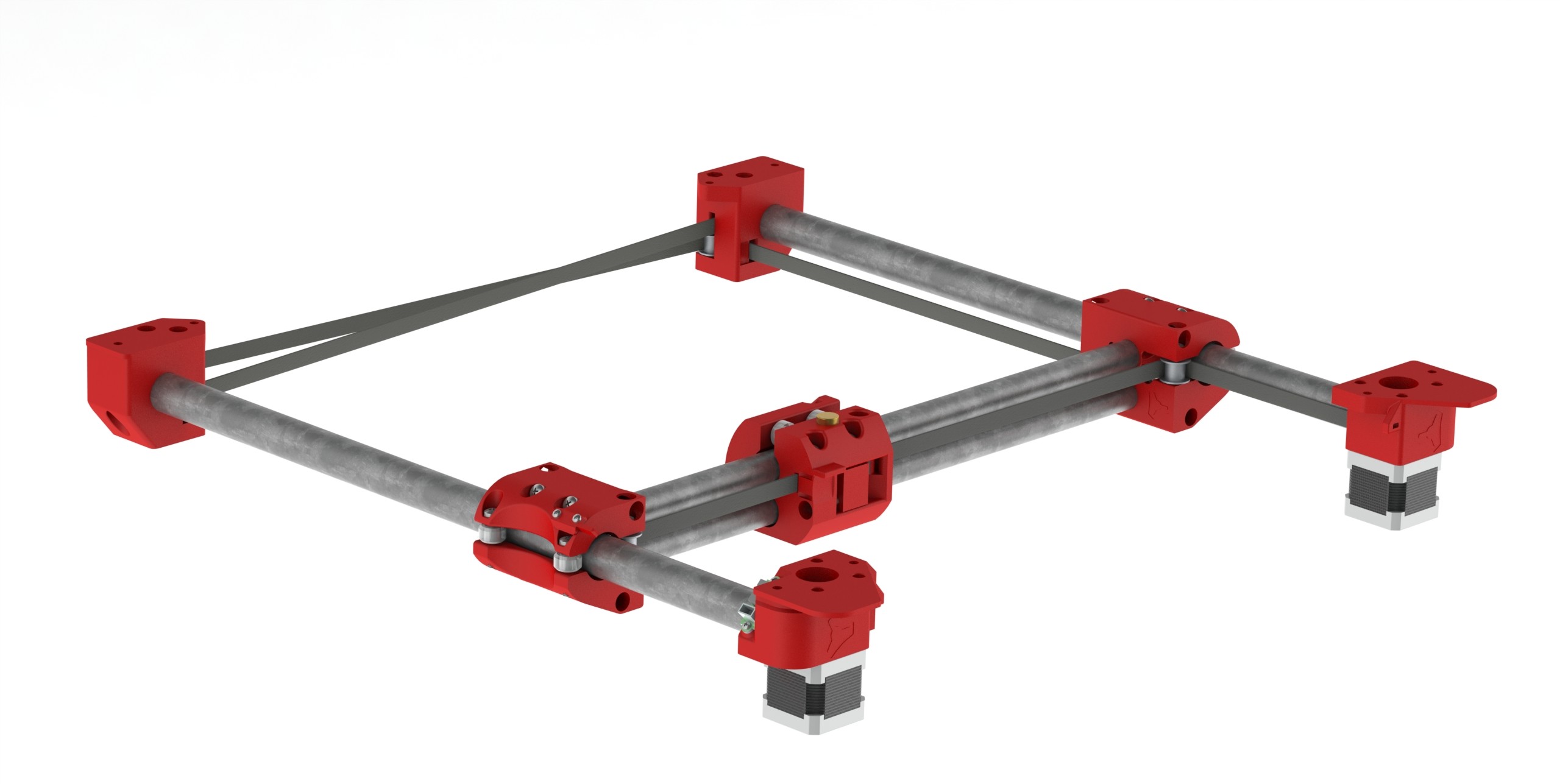
Funky rotation, but I learned a lot. I want to do another with transparent printed parts so you can see how close all the parts and holes are internally.
Ou, Ou, Ou, I want to make one too! Are you ready to post the STL files to GitHub?
Mike
I think so, at least in the current form. It is tough because it brings on the onslaught of questions and need for some instructions and calculators. I have some shipments due (more wheels, idlers, endstops) and I think when they get here I will start posting this.
Please put me on the list.
Mike B.
I’ll also volunteer to be a guinea pig for building the new version. I’ve got my printer warming up now, ready for STLs.
As soon as I get up my outline for the instructions I will release them. I started last night but didn’t get very far.