I did indeed do that. I just did not make any hoopla about it.
I love the mod, and it has been working great for quite some time, and it worked great on the LR3 for a long time.
Your thinking makes sense to me. If you don’t learn the machine’s capabilities before you mess with a hidden belt mod, you won’t have any experience to compare to.
For my own case, I have not noticed any difference between the machine’s capabilities before and after. Moving the belt down can have a detrimental effect that compounds over how much distance it’s moved, so I sought to move it as little as possible to meet the goal. If this mod is costing me any performance, I’ve not been able to detect it. It may be that some expert could devise a test finer than my real-world experience. Anyhow, it’s working great for me.
I think it is an awesome mod and appreciate you making it available to the rest of us. One of my main concerns and hesitation with selecting the LR4 was the perceived difficulty of loading material on to the bed. I am currently planning on using a post into a collet mounted into the bed so the belt can be removed and reset without changing any adjustments so it returns to the same exact location and tension each time it is removed to load material vs hard screwing it down to the bed. With the lowered and protected belt, this will no longer be necessary. I will be able to drive the gantry down the 10 ft Y axis a foot beyond either end the bed and then have zero obstructions for loading 4x8 sheet onto the work surface….unless someone else with real experience (unlike me with just theory) has a better way or knows why this would not work?
My thoughts on delaying the mod is my expectation of having a million questions to pose to this group as I start learning the capabilities of this new tool. However, I have been in IT for over 35 yrs…and I know from hard earned experience is it is easy to blame something that is different or non-standard when there is an issue. If I was having an issue, my concern would be an immediate blame on this mod as the cause of the problem “because no one else has that problem who haven’t made that mod.” That might not be the case with this group, but I have been a moderator on many different type groups over the years and that is a common phycological response regardless of the subject matter and I would like to avoid that, and also learn it as it is built first
As a simpler alternative, you could just add a rail on the non-rail side close to the belt. That’s not actually using the rail. However, this would let you slide material on the rail over the belt.
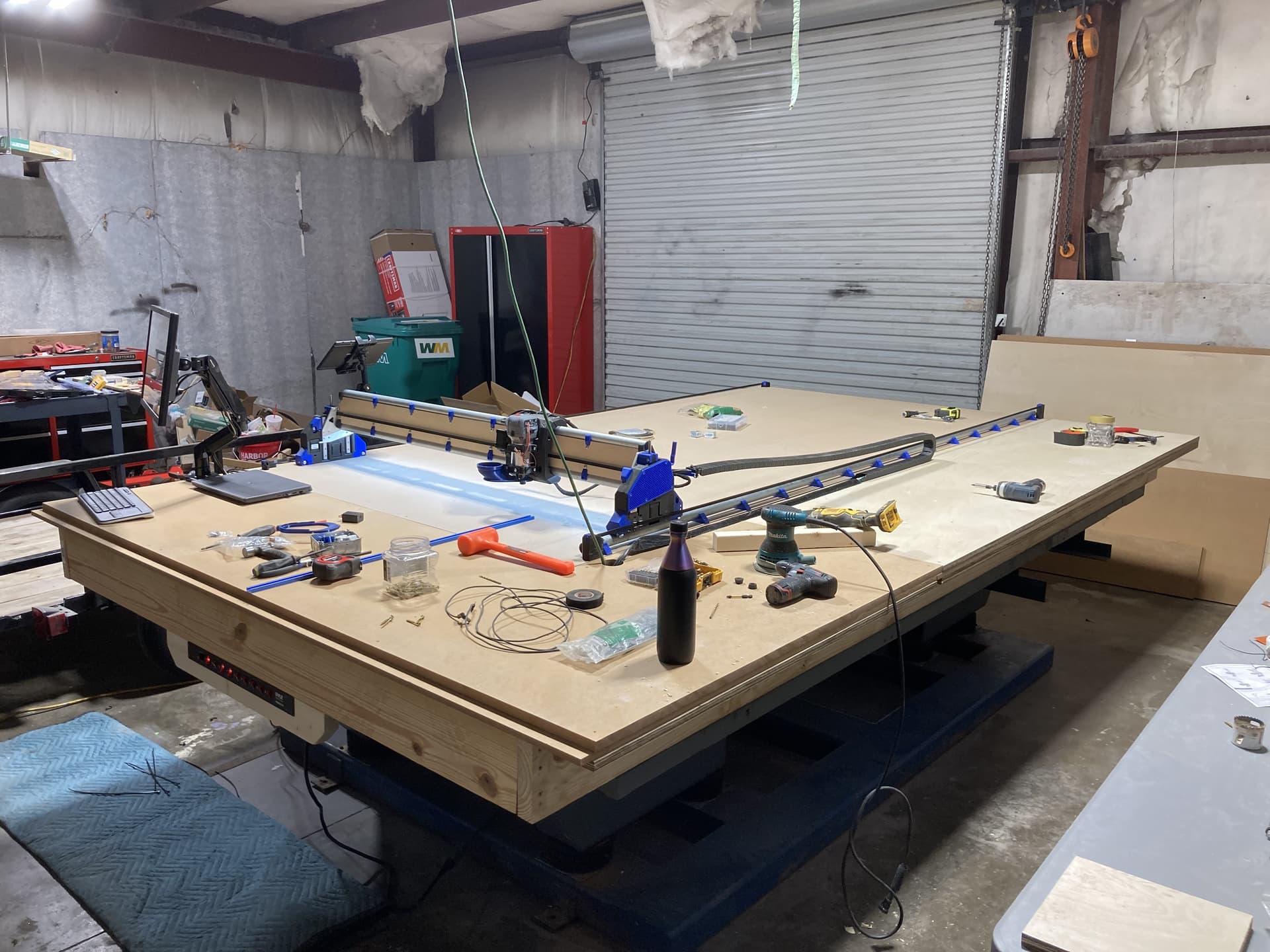
Didn’t take time to snap a quick pic of the progress as I was already late to meet up with the wife for drunkin painting (drink wine and pretend to be an artist for a couple hours…don’t know anything more about it, but I will report back) so I was already in the dog house. But…we managed to get all four belt retainers mounted and the belts tensioned, installed the micro computer, the monitor arm, and the touchscreen monitor.
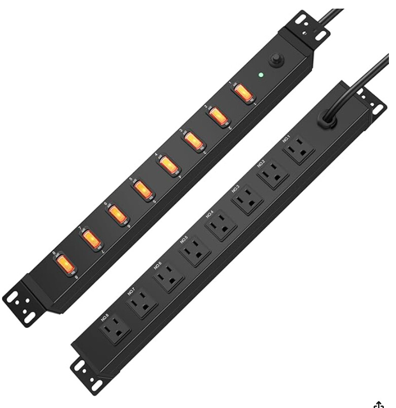
Next I have to drop power to the table from the ceiling. Has anyone used anything like an AV rack outlet controller to manage the power to the various devices, LR4, router, computer, monitor, dust collector etc?
Got the touchscreen operational on a temporary laptop while I finish configuring the micro computer that will be mounted under the table. Have power distribution installed under the end of the table with separate switches for the CNC, Spindle, Computer, Monitor, and Dust Collection.
I have movement on all three axis and will start the process of setting up all the proper configurations tomorrow.
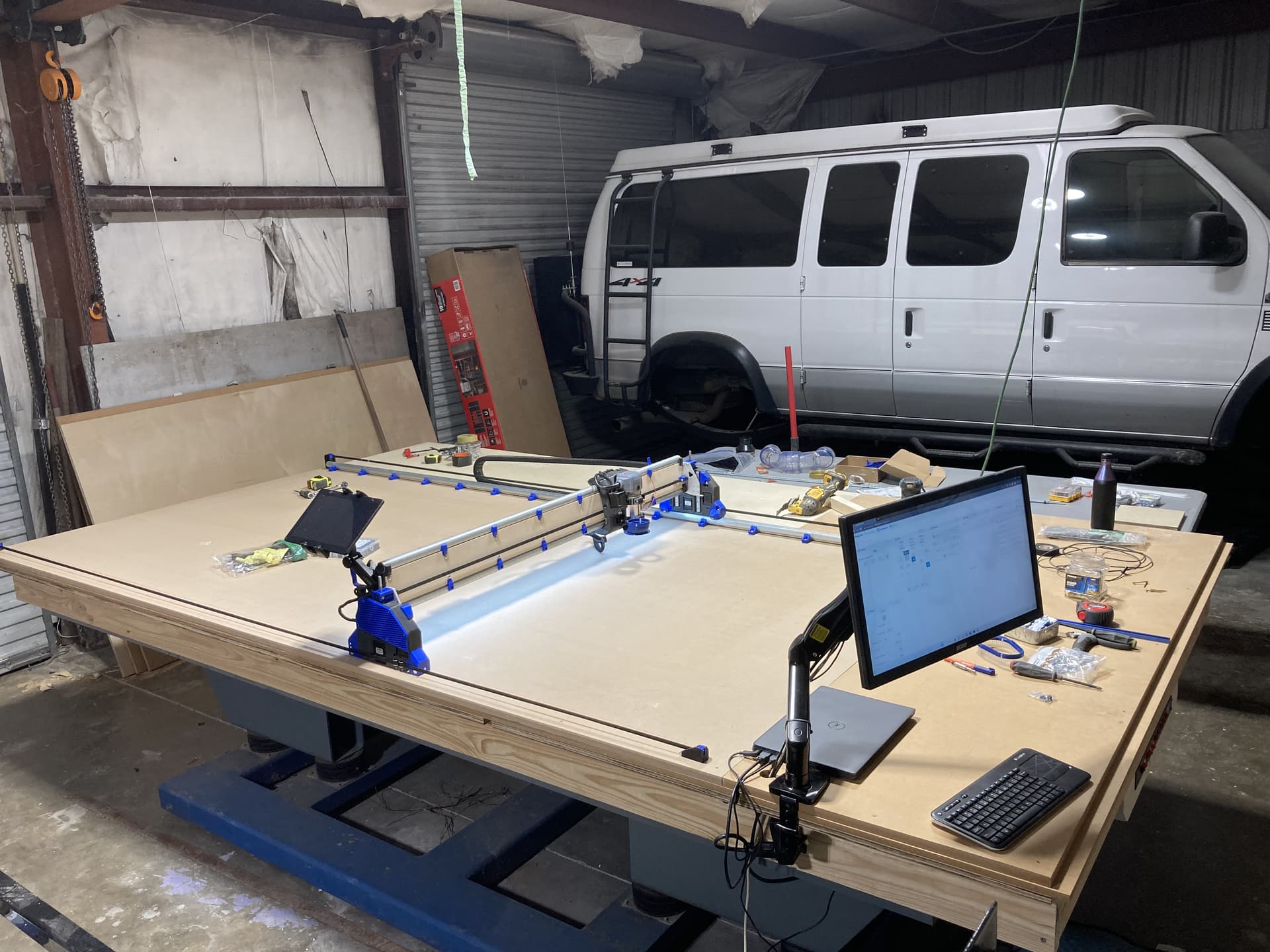
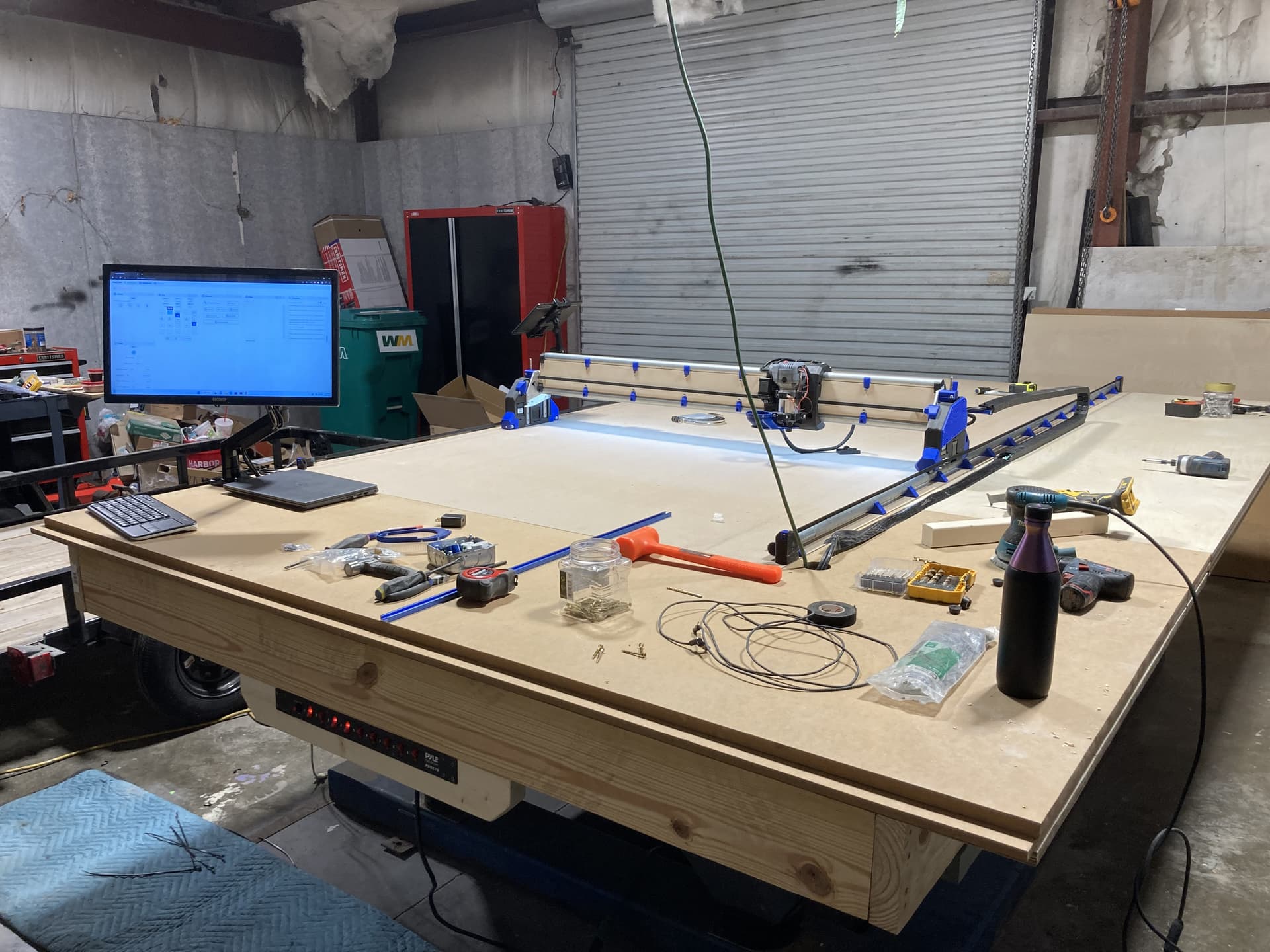
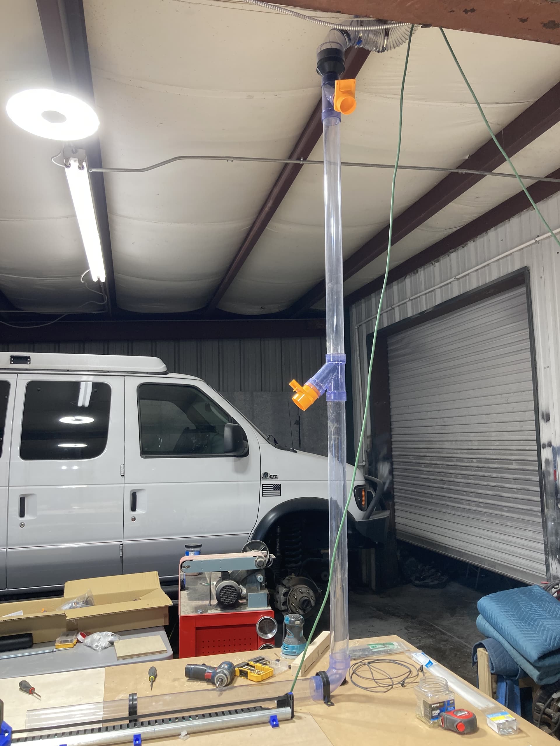
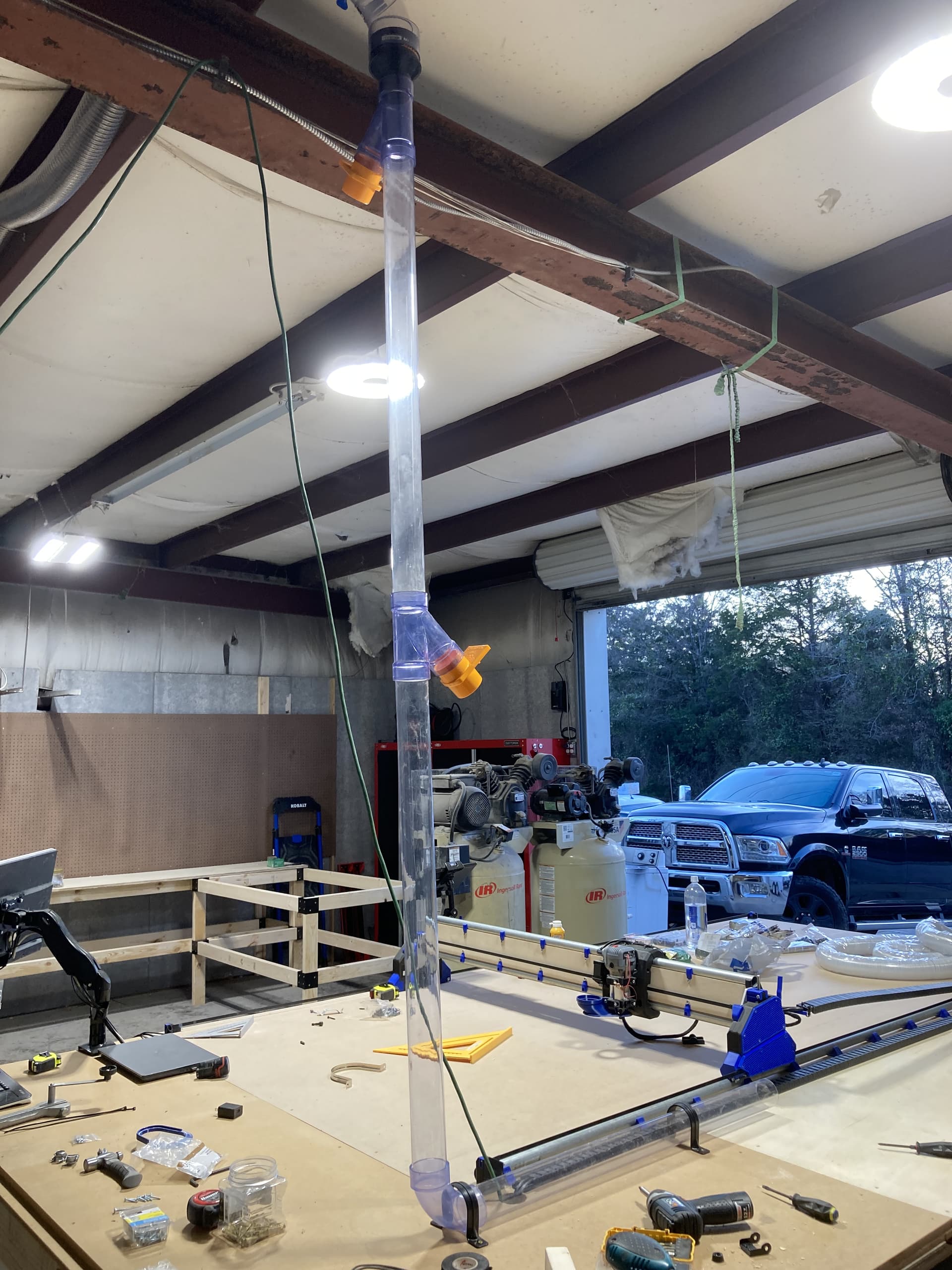
Finally got power run for my dust collector and started my hardlines. I was able to add a remote relay in the dust collection circuit so I can remotely turn it on and off with a keyring remote hanging on my monitor on the CNC table. Hopefully today I will adding in the softlines and figuring out how to get the LR4 to move through full range of motions without hanging up or causing binding.
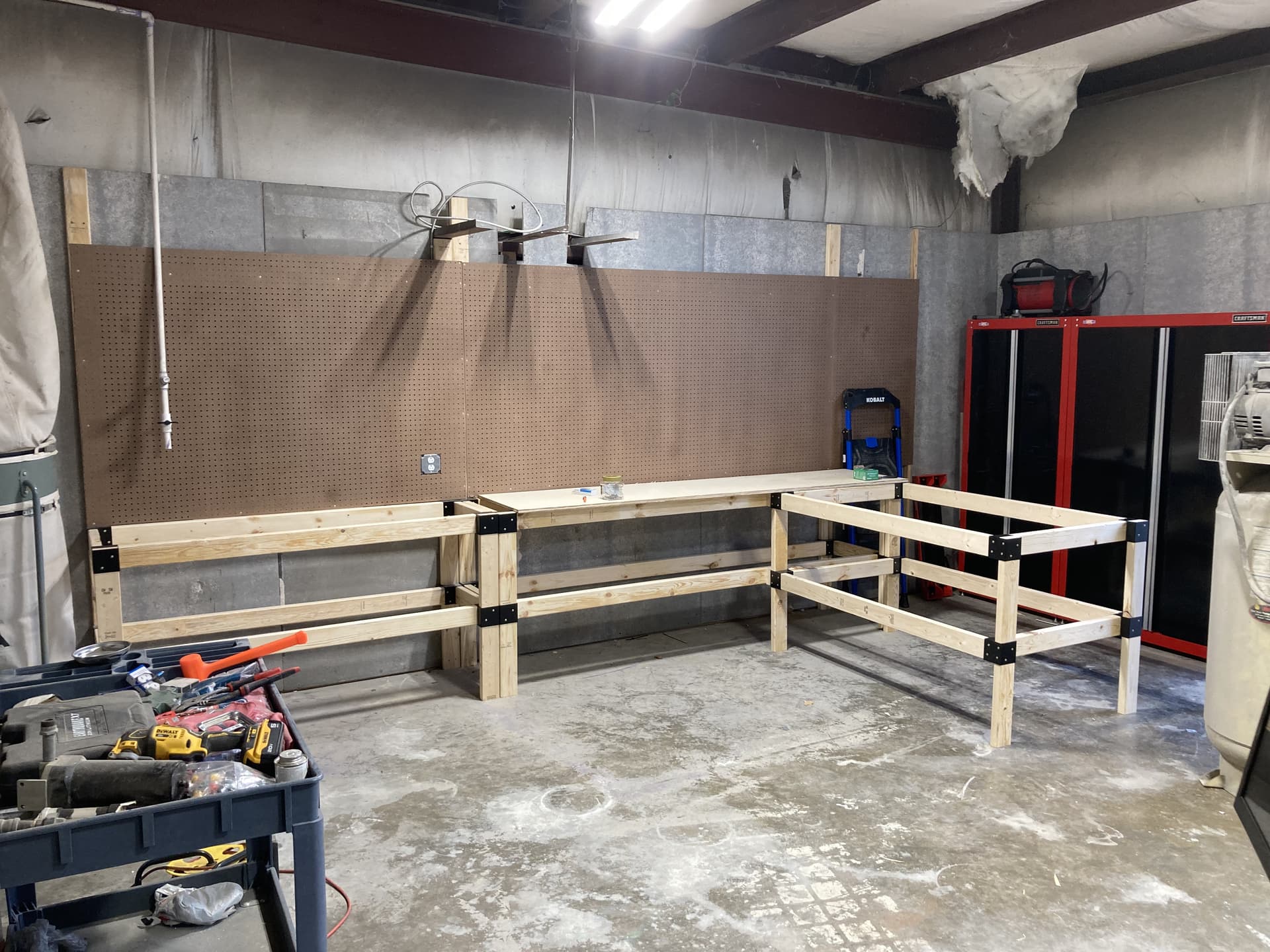
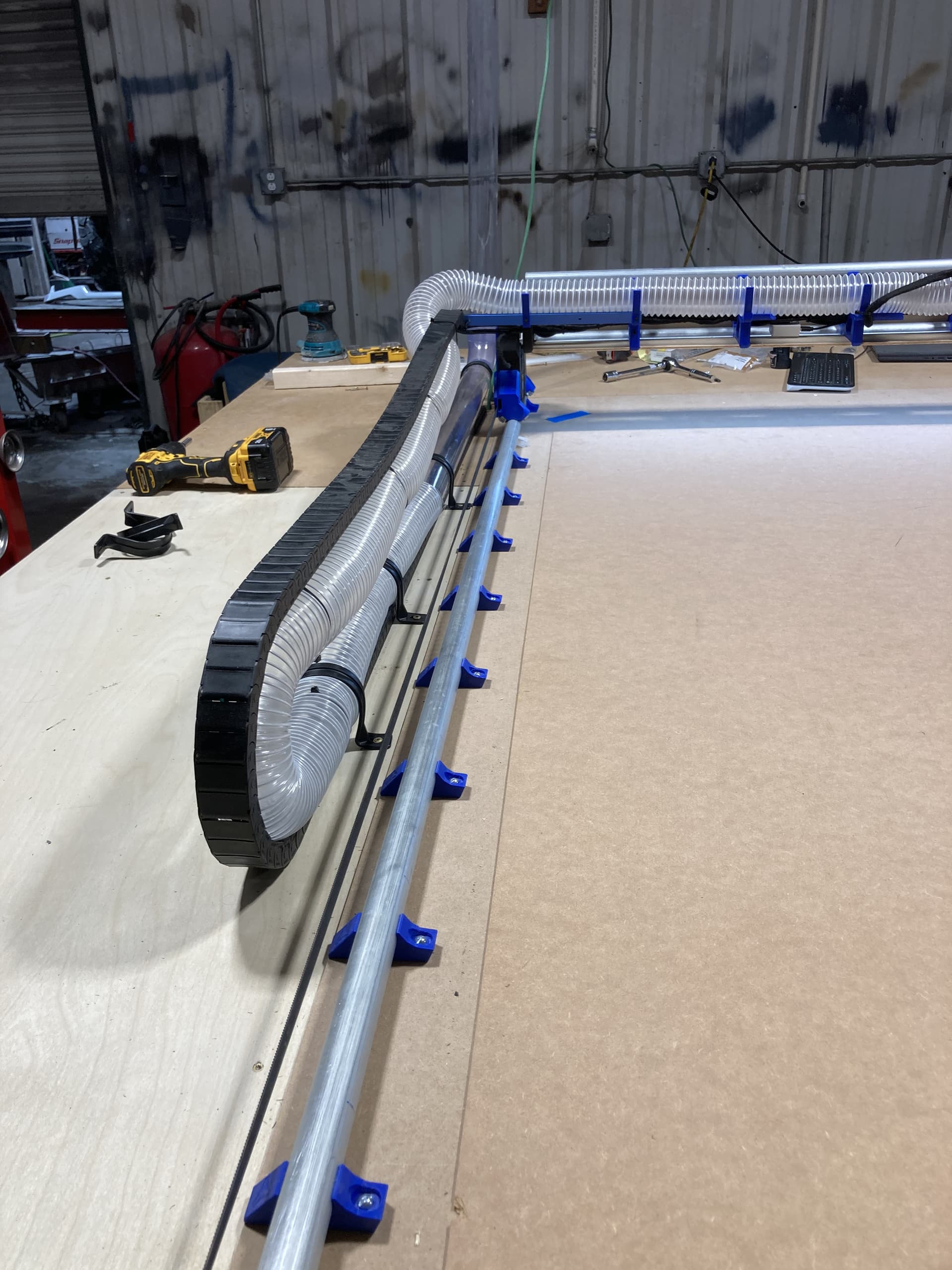
You can see I already have my drag chain mounted and fully functional for power to the gantry, LR4 and spindle. That part already works very well. I bought the 10 gauge wiring and conduit to get power to the table vs the current extension cord. On a side note, has anyone priced copper wiring recently?!!? OMG! Anyway…should have more significant updates later today as I spent much of yesterday building out work benches and routing 4” dust collection trunks around the shop. Next I have to get the air compressor installed and plumbed as I also picked up the wiring and disconnect for it.
The 30” wide extended workbench will have retractable castors that can be lowered and the workbench disconnected from the main bench and rolled around the shop as a work/build table that attaches to the main workbenches when not needing to be mobile. That way I can have an island work table that is not taking up valuable shop floor space when not in use.
So we finally made sawdust…but first a HUGE shout out to Jonathan at NorthWoods for his invaluable telephone tech support helping us get the LR4 squared up and zeroed in today. Our final numbers were less than .02mm difference over the full width X axis and our diagonals were less than .25mm over the full 10 ft table. I think I articulated those correctly. Jonathan can correct me, but these really low numbers are a true testament to the LR4 design and the quality of Jonathan’s build.
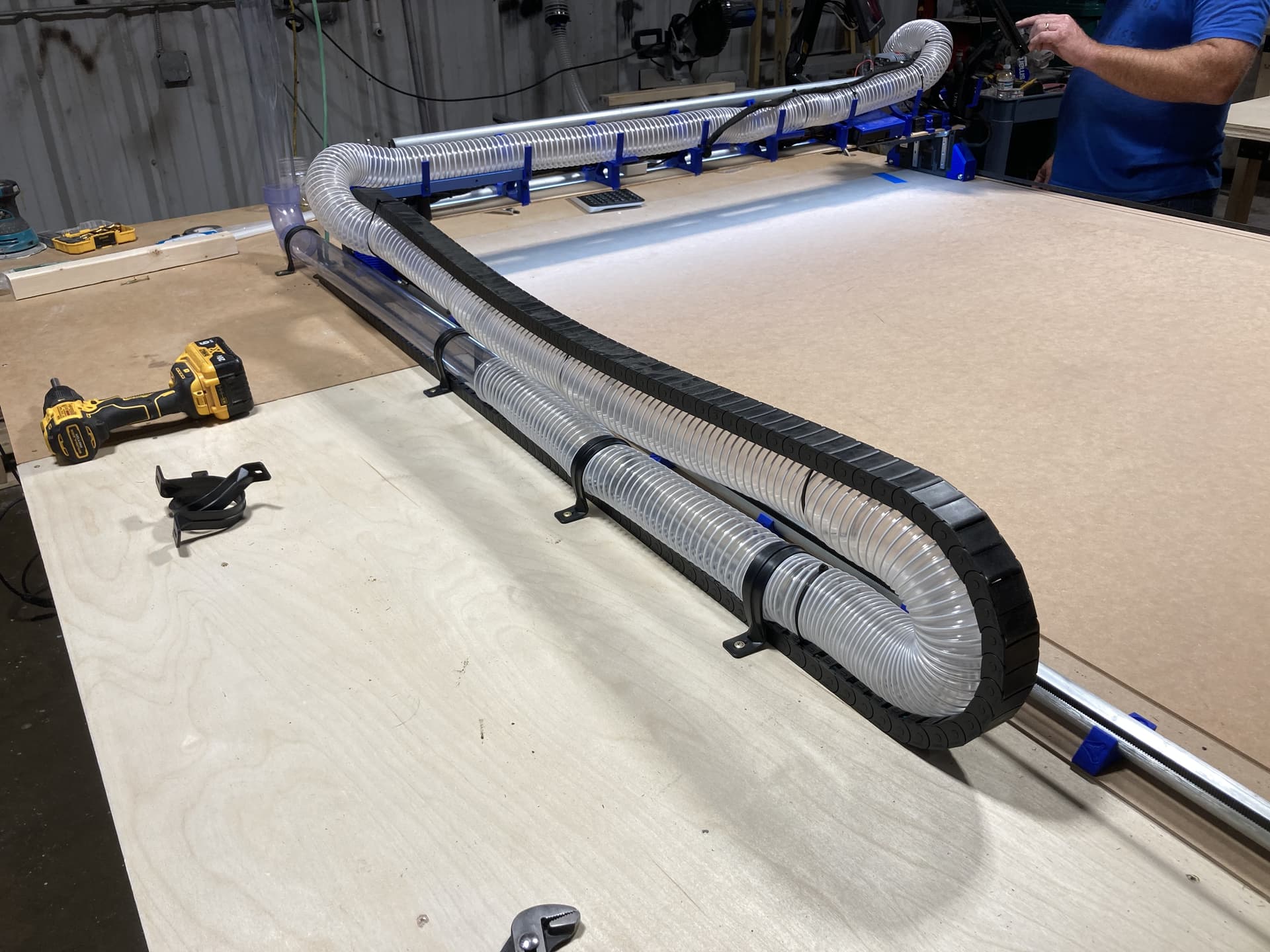
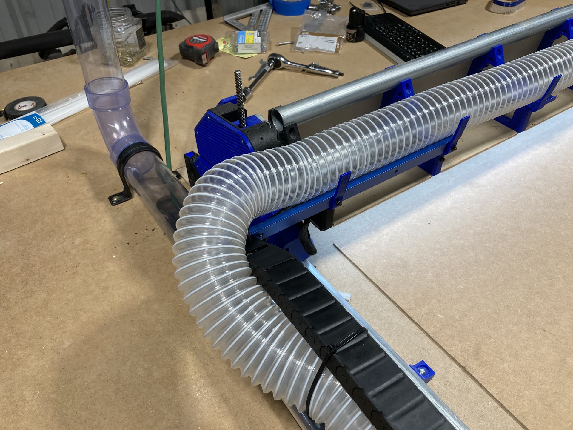
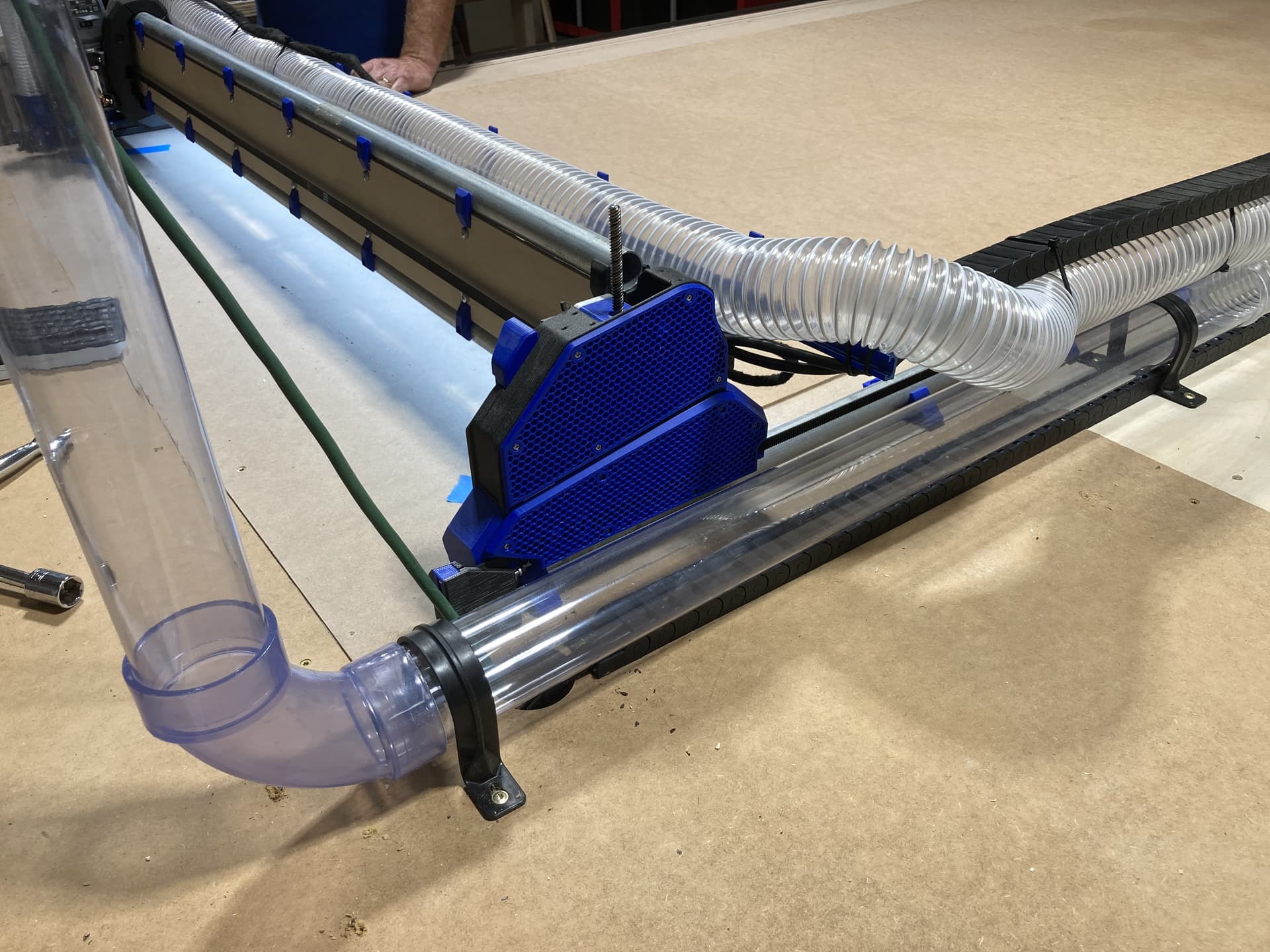
Ok, now lets talk about dust collection and power cable management. I read everything I could find in the forum as well as watching tons of videos. I came to the conclusion that although there are numerous ways to do it incorrectly, there does not appear to be a single solution that works for everyone…so I designed my own.
I used commercially available light weight drag chain and 2.5” duct hose. I purchased a pair of 12 gauge stranded copper extension cords and stripped the outer coating from the section contained within the drag chain so it was much more flexible. I left the coating on the section threated though the LR4 trusses, one for the Jackpot power supply and one for the spindle motor. The other end I plugged into the power distribution mounted under the end of the table so now I can control everything separately.
I fabricated an extension arm from light weight T track (also blue) and bolted it to the X Axis hose supports so it extends beyond the guide rail. This enables the power to be internal to the chain and the dust collection hose strapped to the drag chain without interfering with the Z-axis movement.
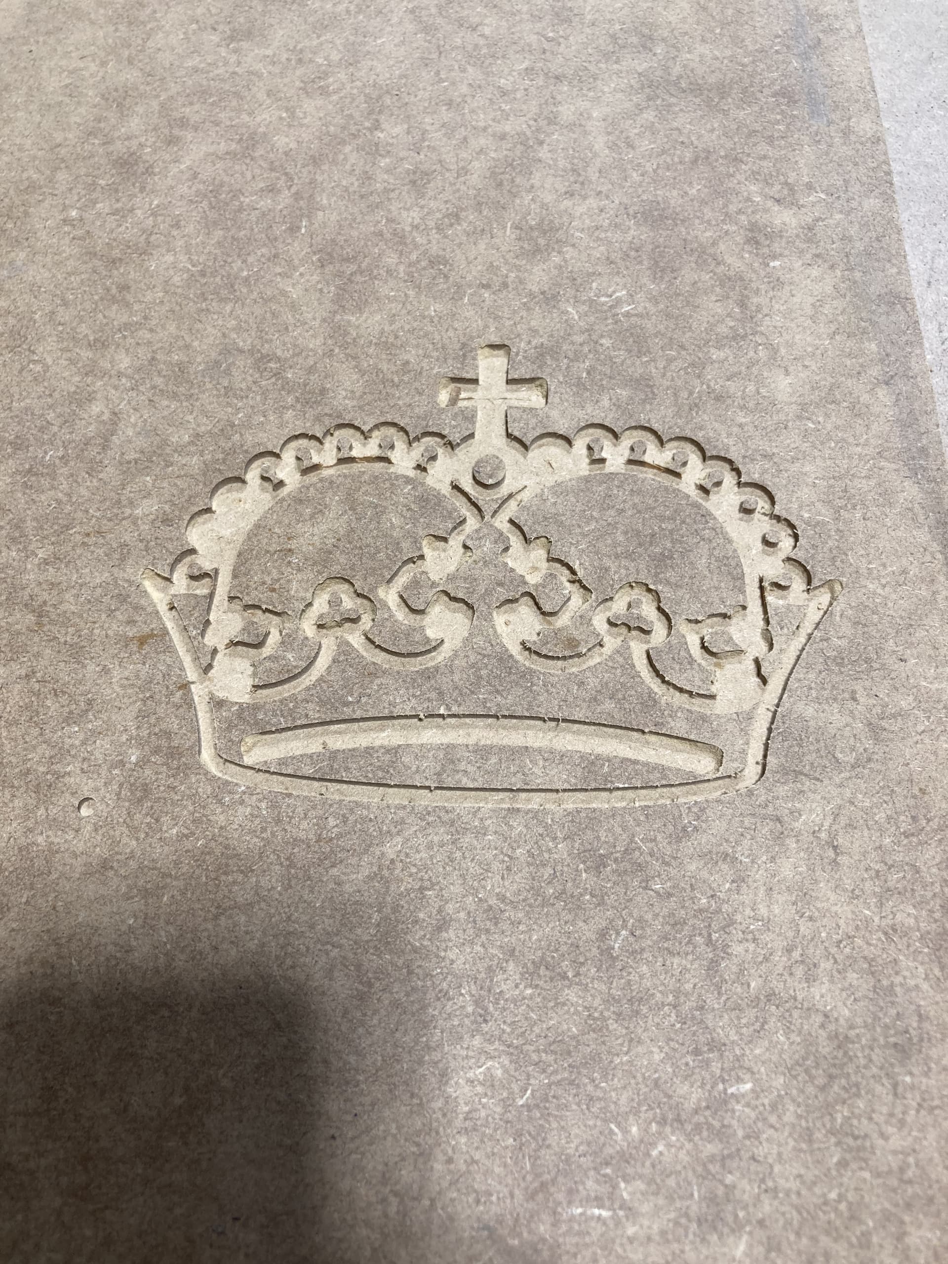
Ok…I am going to need some assistance please as I am a bit frustrated after a quite unproductive afternoon. I downloaded EstlCAM and working through the online config and a call to Jonathan to understand that I was attempting to use EstlCNC vs EstlCAM, we got it configured to what we thought were the correct specs for exporting gcode for the LR4. We then configured a couple tools. Knowing I wanted to carve and having already snapped the tip off yesterday of the only v-bit I had purchased from Ryan, we purchased a 1/4 shank 3/16 taper carving bit with a 7.5 degree angle at the local WoodCrafters. I then purchased a couple pieces of foam in which to play. I added the new bit details into a new tool and saved it (on the the second attempt).
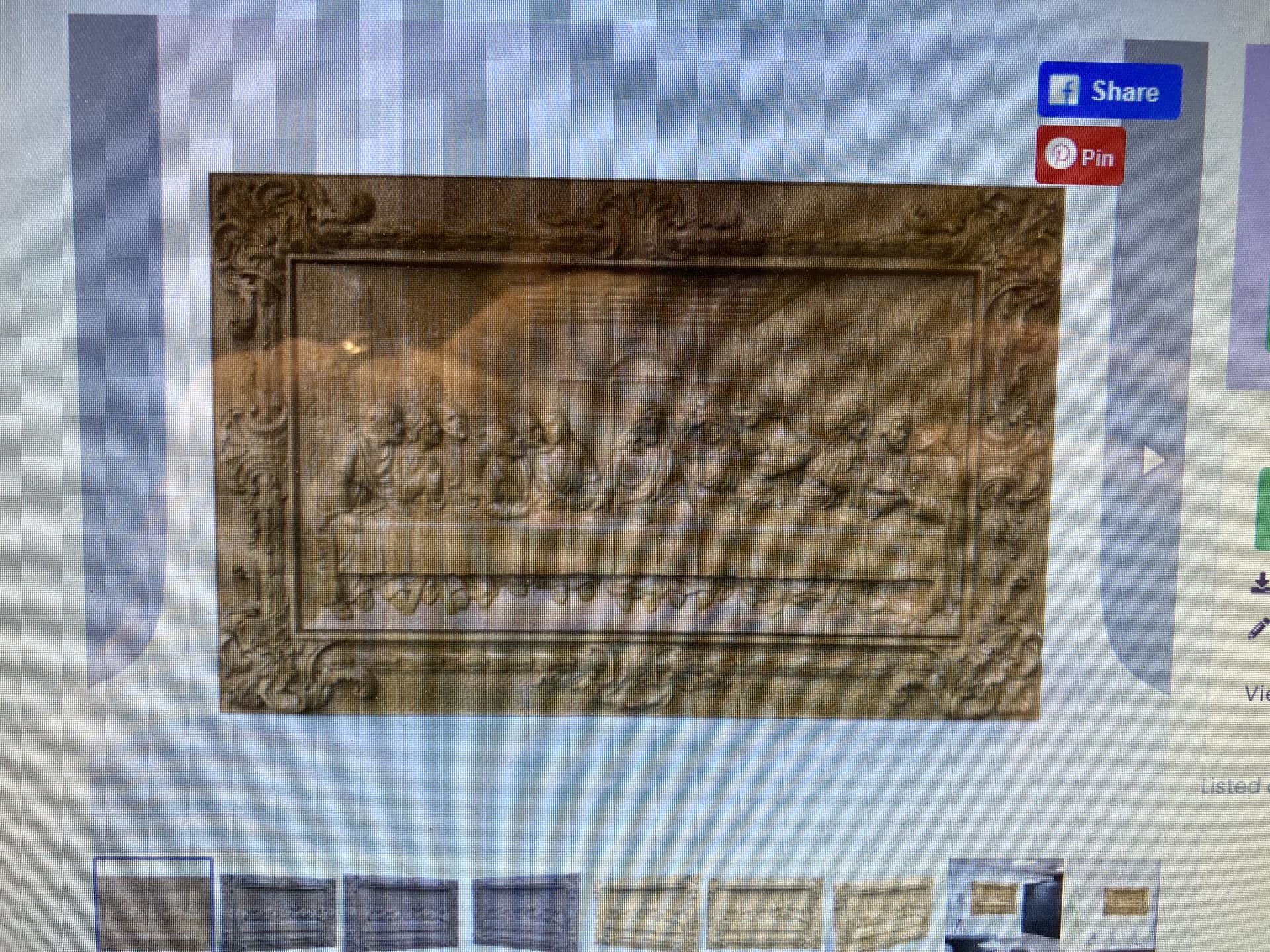
I then logged into Creative Fabrica and downloaded the STL for an image I wanted to attempt to carve. I imported it into EstlCAM and then exported the gcode.
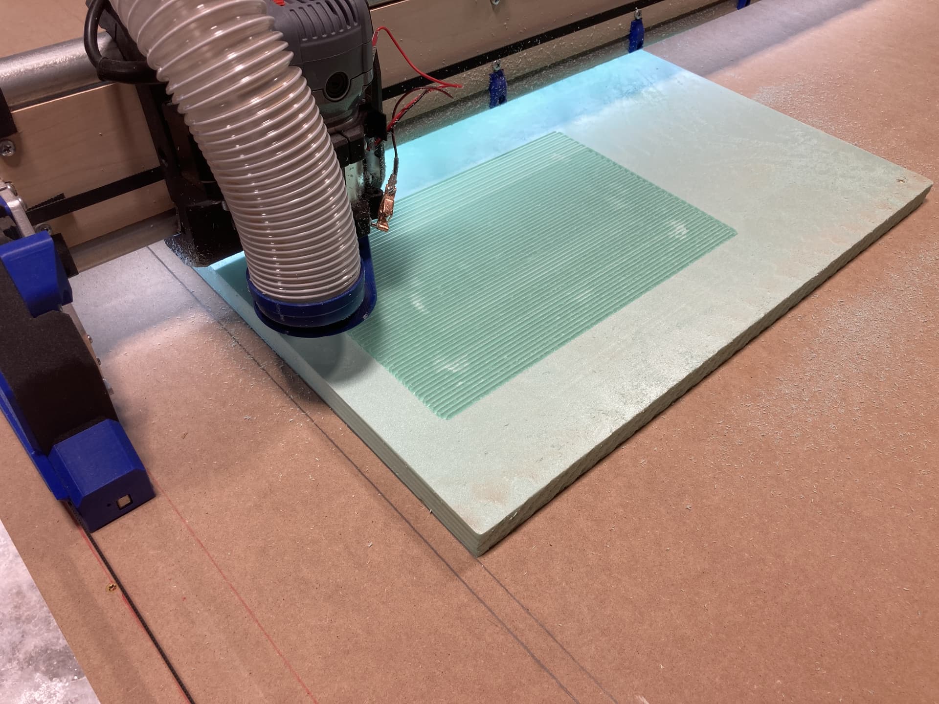
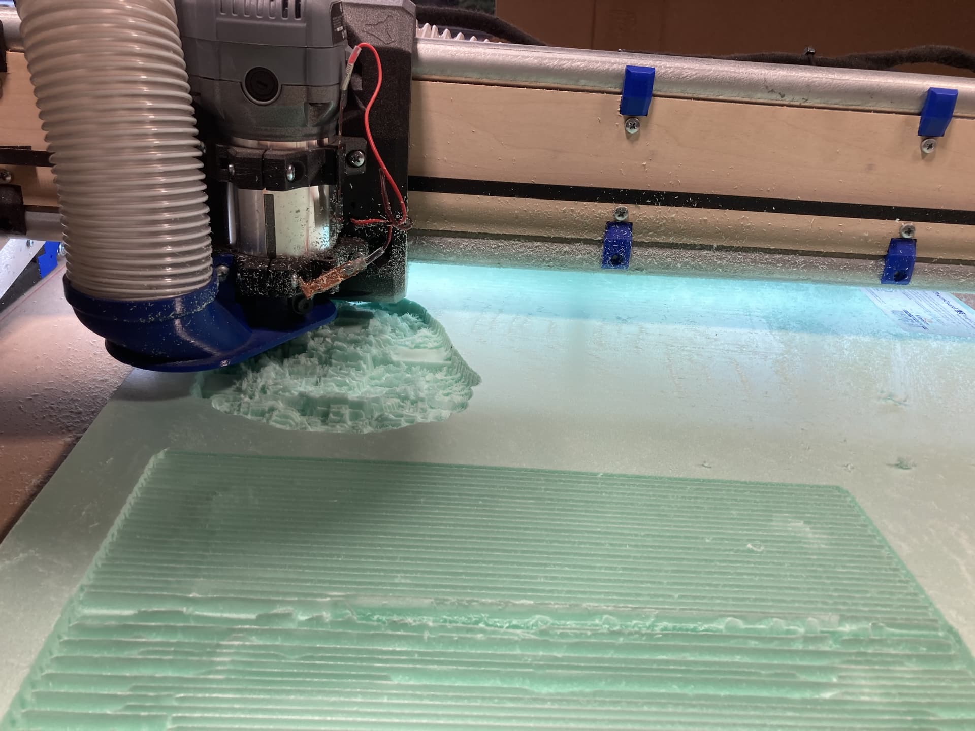
I selected a Predator and adjusted what I thought were the settings, increased feedrate to 60mm and max depth to 12mm and exported the gcode. It said 25 minutes so I uploaded to the LR4, rehomed, established the work home, and probed the bit again to establish Z and started the carving.
Needless to say I am a bit frustrated this evening. I am hoping someone/anyone can provide some assistance even if it is a known good gcode for testing carving as my goal is to do carvings and eventually inlays on this LR4….but after today, that does not look to be in my future anytime soon…and I’m beginning to question my decisions
What’s the Maker site, does it generate .STL or gcode files?
Am confused by “imported it into EstlCAM app and then exported the gcode”, did you import a .STL or gcode into EstlCAM and then export gcode again? I normally see people importing .STL, .DXF, .SVG into EstlCAM.
Asking because opening a .gcode file in EstlCAM ends up launching the “EstlCAM CNC” app which you can use to send gcode to your connected CNC, and control motion. Are you using “EstlCAM CNC” or FluidNC Web UI to control your LR4? Sorry if you mentioned already, I didn’t read entire topic.
You are trying to start out with one of the hardest things to do. Maybe start with a few simple boxes first until you understand the machine and software.
Inlays are completely different from 3D-carving when it comes to machining. I have some tutorials up on it on YouTube.
I was incorrect. I downloaded the STL not gcode. I opened the downloaded STL file in EstlCAM, selected my tool (Carving Bit to I defined in the tool list), edited the feedrate and max depth, and then exported the gcode from EstlCAM (to include the configured start and end code from the EstlCAM setup performed earlier when configuring the EstlCAM) into the exported gcode.
I then copied said exported gcode file onto the Micro SD card (supplied by Ryan to Jonathan with my build parts as not to be an incompatible card) and then ran it (selected the file from the SD panel and pressed the play button) from the FluidNC Web UI LR4 control interface using an android tablet attached to the LR4 gantry and connected to the LR4 via it’s AP. I also mounted a full computer on the table to run EstlCAM and make edits to the gcode files and then transfer them via the SD card as there seems to be potential issues if you try to connect directly to the JackPot board other than through FluidNC Web UI via AP. I plan to work on that issue in the future, but now, the SD card sneaker net works.