Download from Printables: LowRider v3 Jackpot CNC Controller Board case with 25mm added room, and plexiglas window v1.1 by Doug Joseph (design8studio) | Download free STL model | Printables.com
NOTE: This is v1.1. If you were looking for v1.0 - click here.

Changes in this “v1.1” remix:
- Change to the BASE:
- Created some additional space for wiring by trimming out some unneeded thickness leftover from the previous “add 25mm” remix. i.e. “Trimmed some fat.”

- Created some additional space for wiring by trimming out some unneeded thickness leftover from the previous “add 25mm” remix. i.e. “Trimmed some fat.”
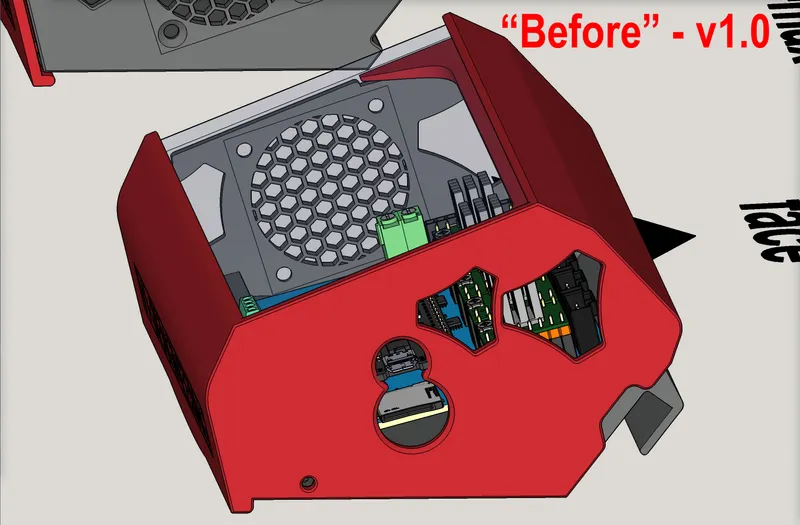
BASE “before” - v1.0:
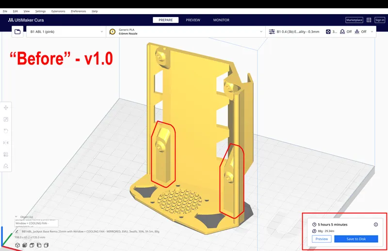
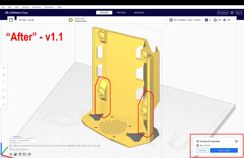
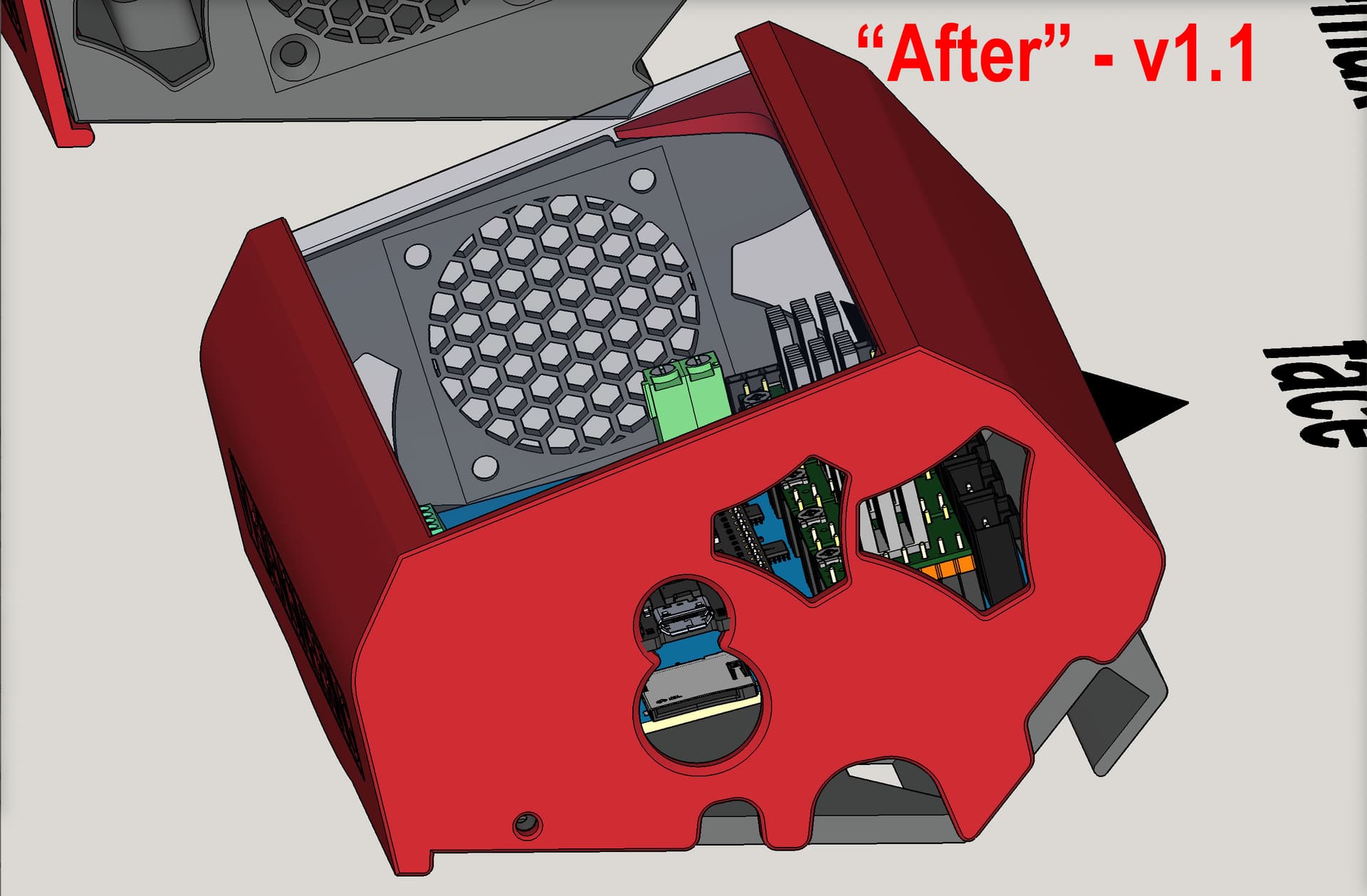
BASE “after” - v1.1:
- Changes to the LID:
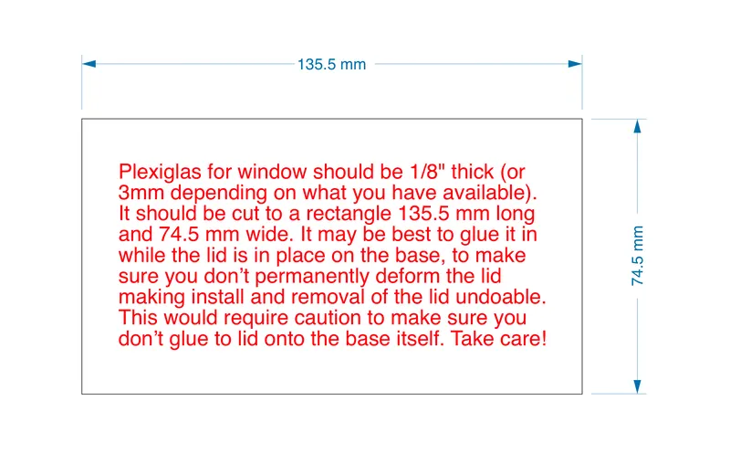
- Made the “window sills” a little bit deeper, to make it easier to hide any unsightly glue that would otherwise be visible after attaching the window, and to allow more forgiveness if the acrylic window piece happens to get cut less than perfectly.
- Added notches at the bottom of the lid, so wiring can pass there instead of being “threaded through a hole” — allowing the lid to be installed / removed without having to deal with wiring in the process, and without disturbing wiring. See my comment below from over here:
In my various remixes for the SKR cases, I notched the bottom of the lid so that it could be removed without threading wires through holes, and just now I had to manually make cuts in this lid to create a notch at the bottom, so that trunk of wires could exit without binding between the Jackpot and the lid.
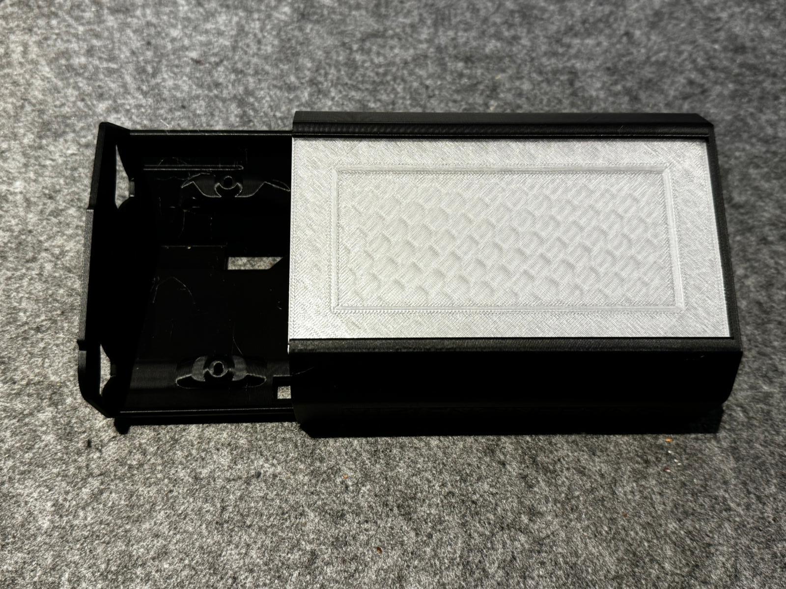
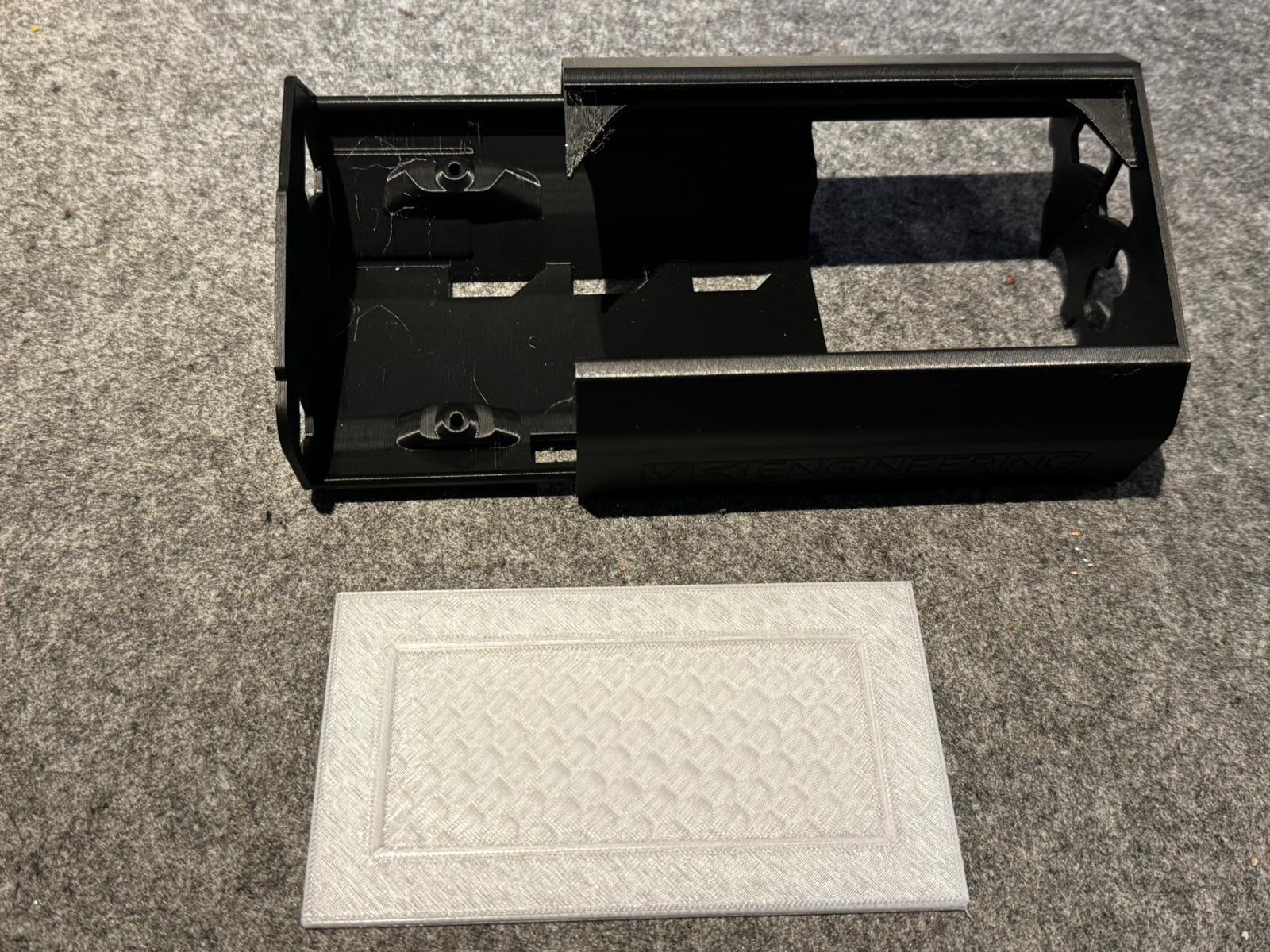
LID “before” - v1.0:
LID “after” - v1.1:
All the remaining info is copied and pasted from the “v1.0” release (except the photos / renders are updated):
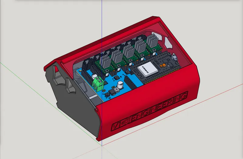
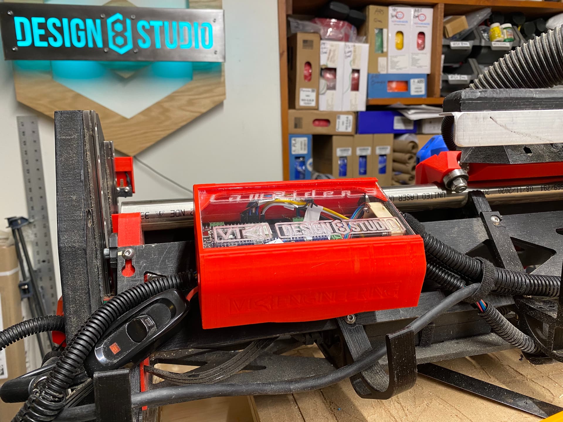
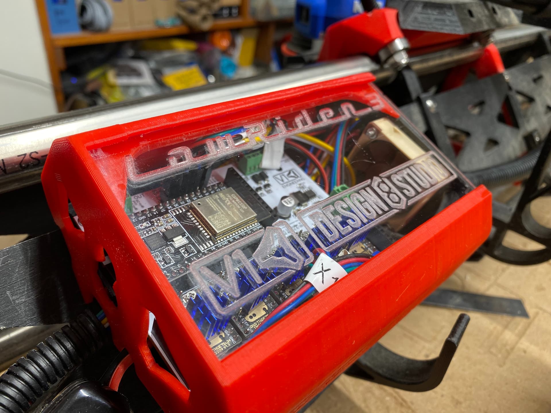
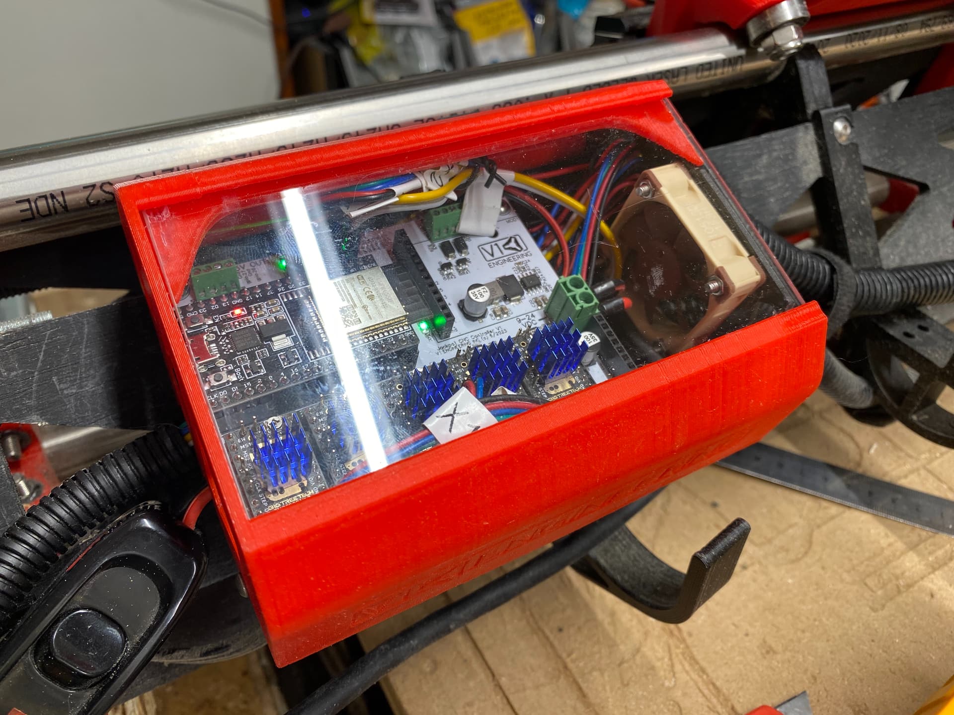
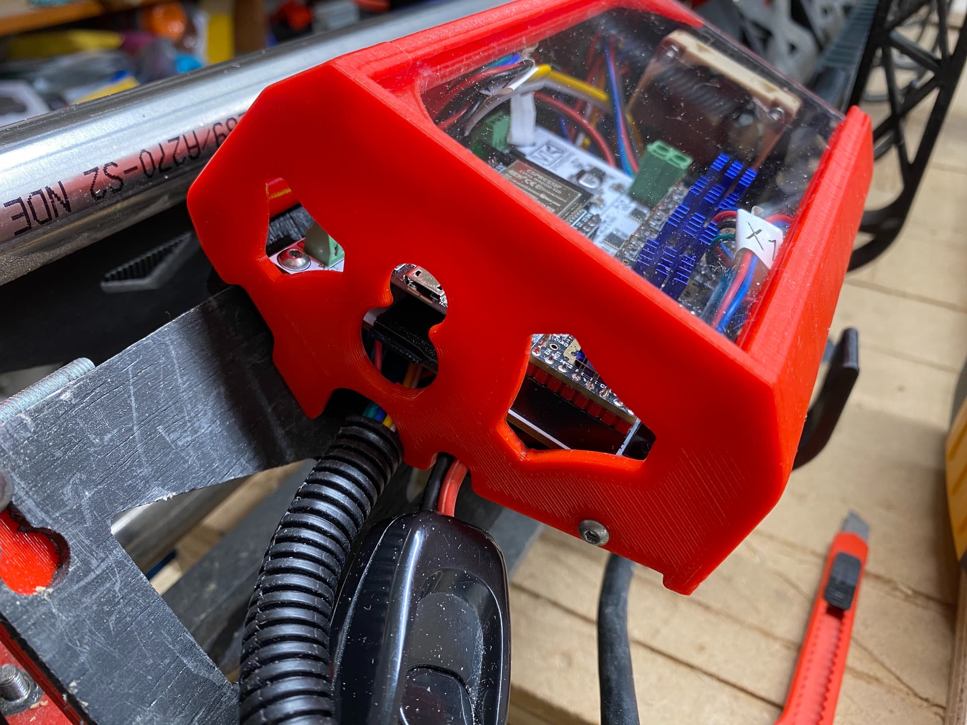
LowRider v3 CNC: new Jackpot board getting its heat sinks installed:
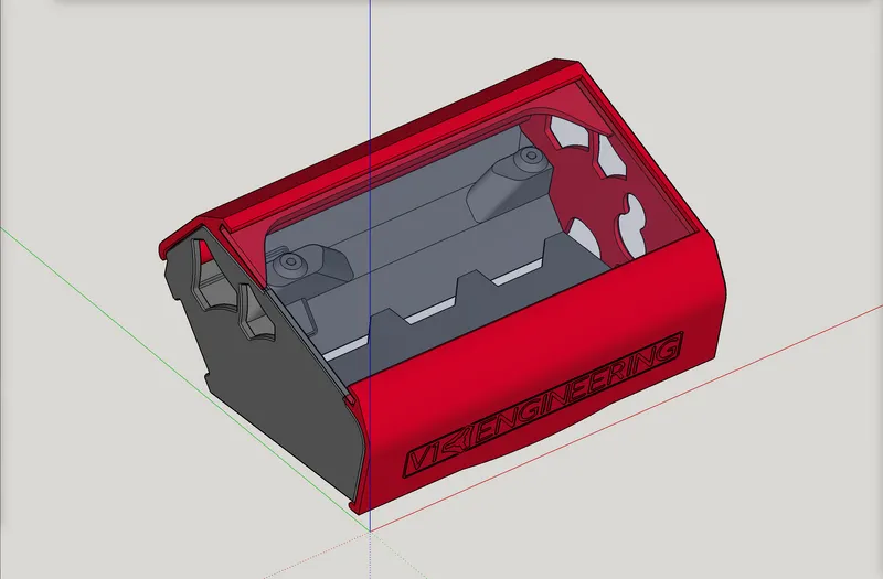
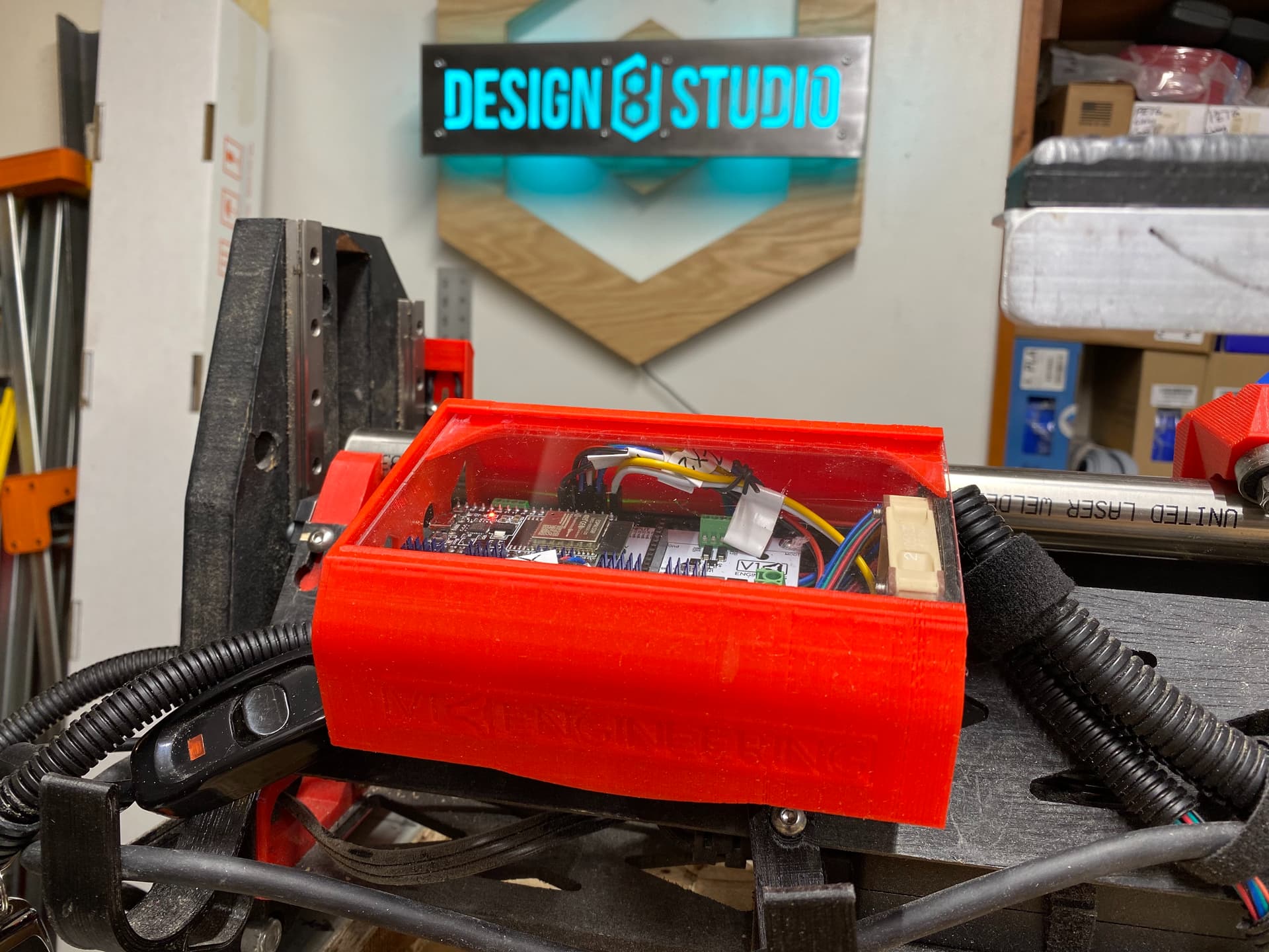
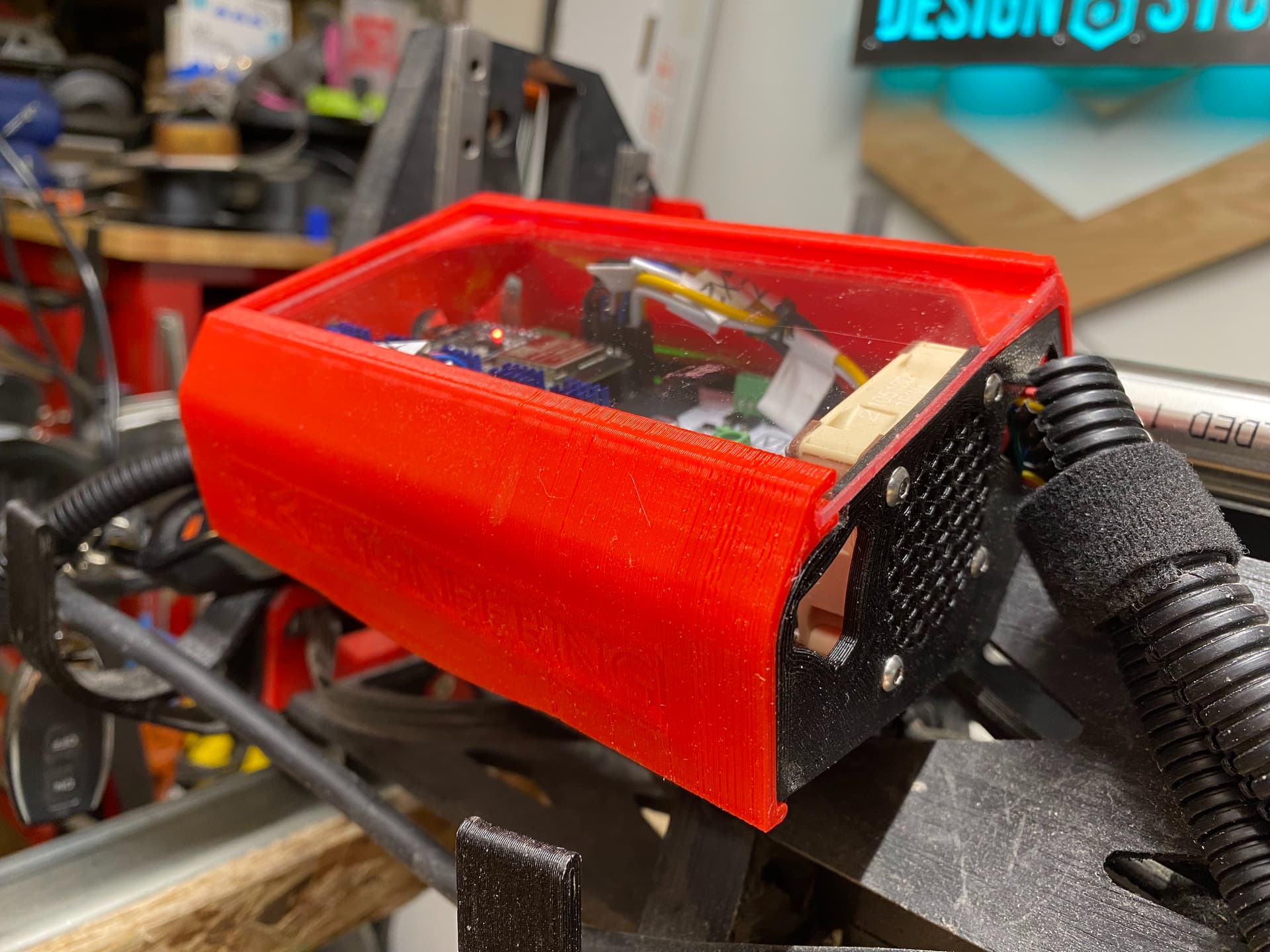
Just finished my remix work on a Jackpot case / control board box that combines Ryan’s @vicious1’s excellent design, with @Tokoloshe’s great idea of a plexiglas window on the lid, combined with @Jonathjon’s great idea to extend the length by 25mm for room for his add-ons.
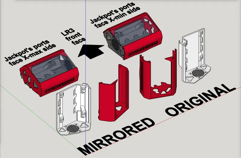
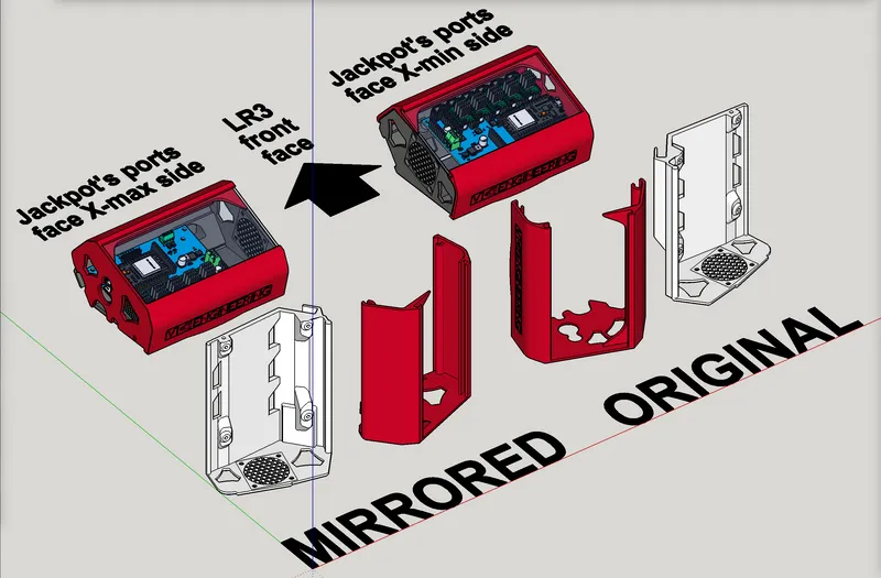
A couple of bits of extra work I did is that now it no longer needs a corner ground off as with @Tokoloshe’s original, and I went ahead and made a mirrored version since I will need mine to have the board’s ports facing the X-max side instead of X-min. Also, because the “hanger” on Ryan’s original was a teensy bit too tight to fit on my ¼" plywood strut (which is probably thicker than it‘s supposed to be), I widened the hanger’s reach by 1.5mm.
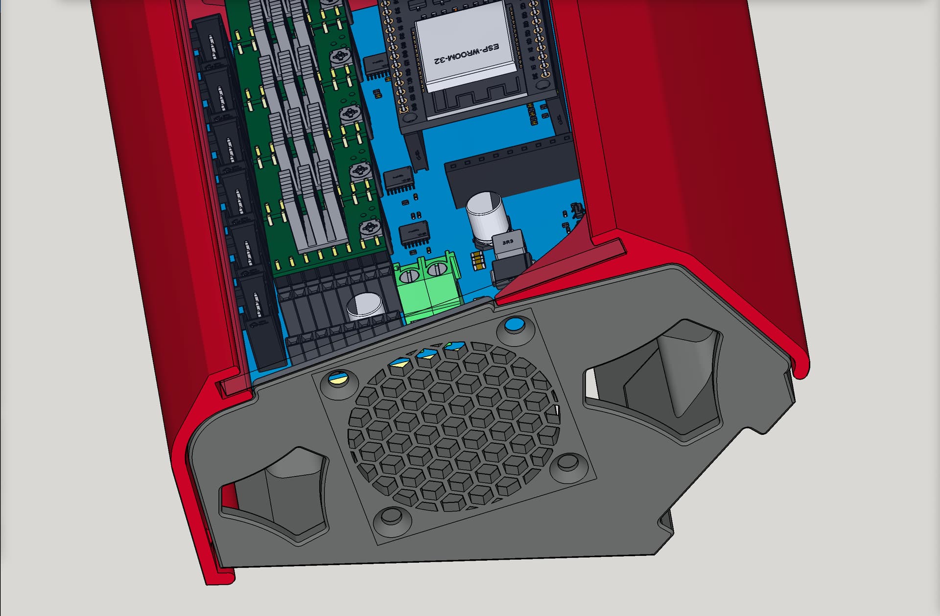
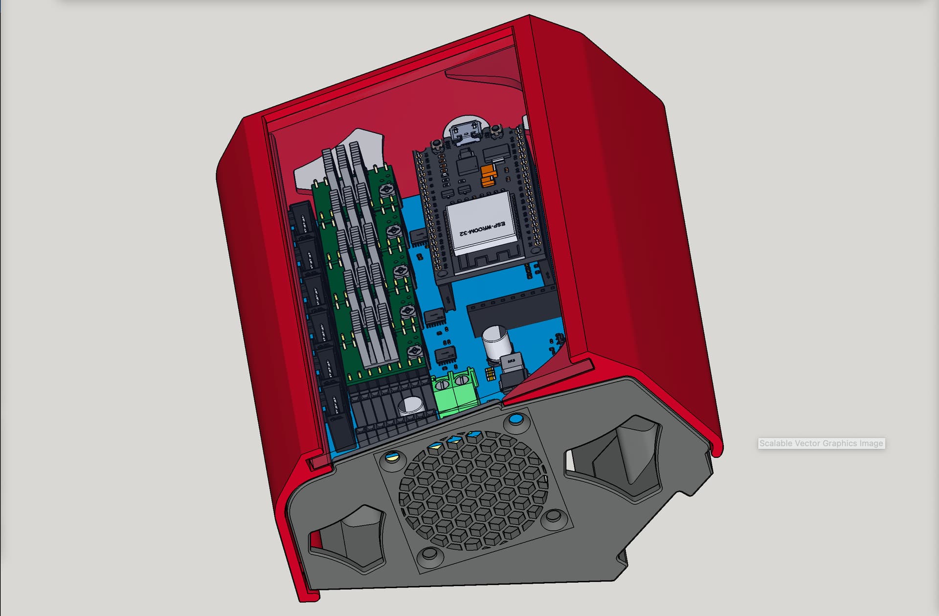
Also, I have added a choice of bases — one with and one without accommodation for a 40mm cooling fan — in case someone already has one on hand to use, or considers it important enough to get one and add it.
I am astounded with how much smaller this case is than the ones for the BTT SKR.
I’m currently printing mine, but below is a preview from 3D renderings.
FAQ:
Q: Where can we buy the Jackpot CNC controller board?
A: You can buy the Jackpot CNC Control Board (a FluidNC board, which is GRBL compatible) here: Jackpot CNC Controller – V1 Engineering Inc
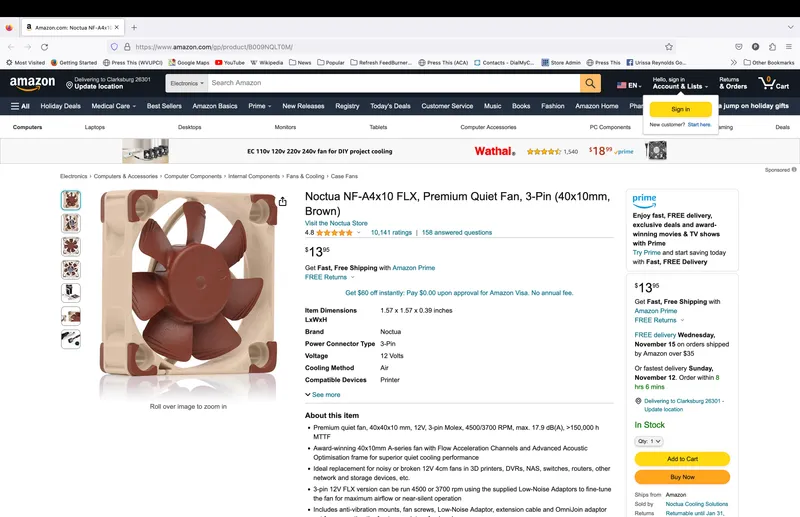
Q: Which cooling fan did you use for this board?
A: I used a super quiet Noctua brand 40mm cooling fan. Here is an affiliate link to the one I am using: Amazon.com: Noctua NF-A4x10 FLX, Premium Quiet Fan, 3-Pin (40x10mm, Brown) : Electronics
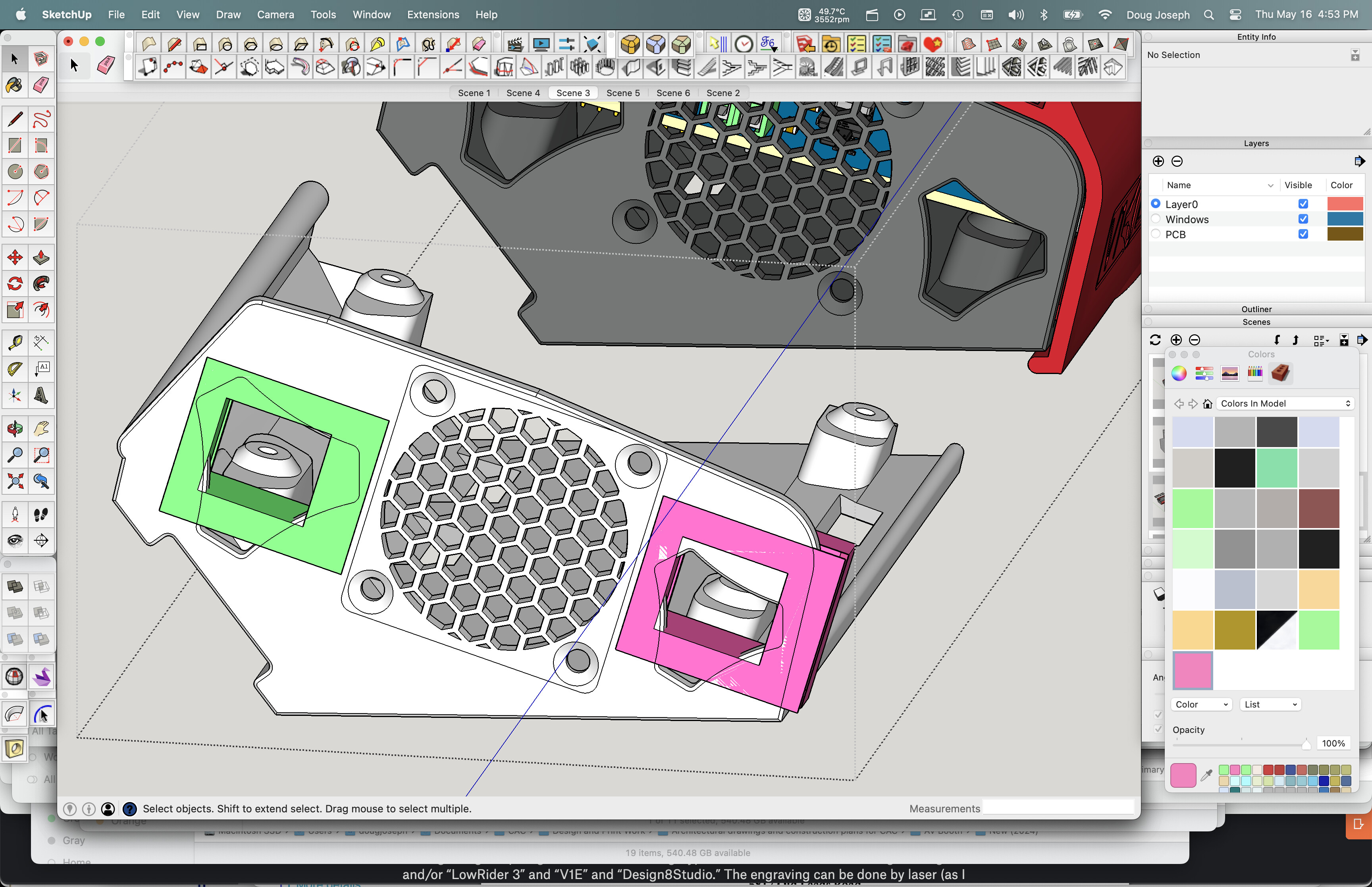
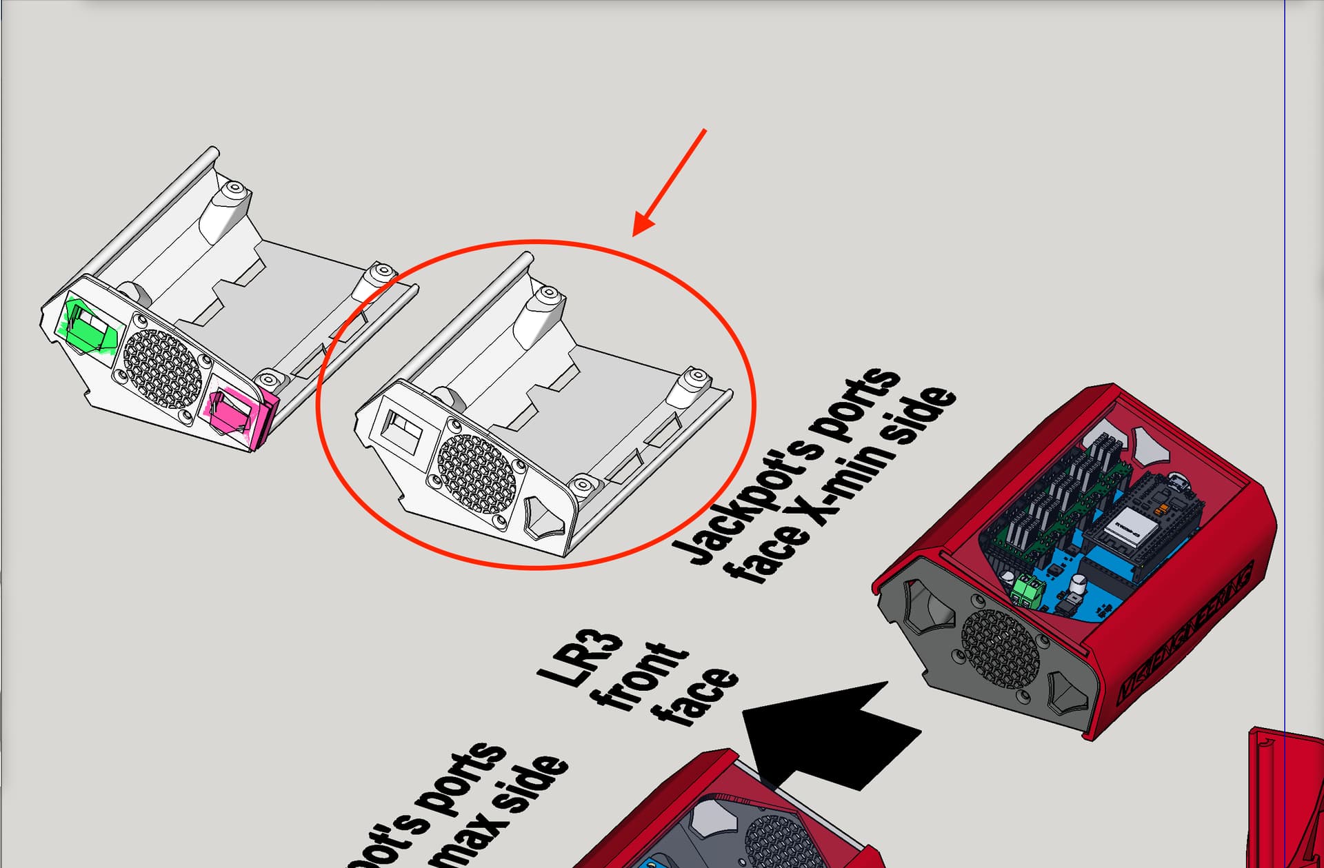
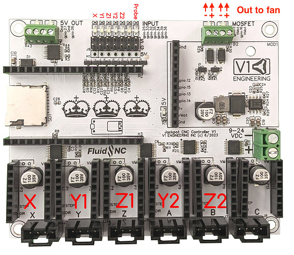
Q: One of the case base options has a spot for a 40mm cooling fan. Where does that get wired to on the Jackpot board?
A: One of the easiest and best ways is to not connect the fan to the board, but directly to the power supply that feeds the board, since the volts must match anyway. Nevertheless, I connected mine to the board. [UPDATE: Well, I soon afterward decided that rather than turning the fan on by a button press (or gcode), I’d rather have it come on automatically when the unit is powered up, so I re-ran my fan wires, and tied them into the main 12V power lines. Now my fan is “always on.”] The Noctua fan that I used runs on 12 Volts. However, the method I used can work with fans made for either 24V or 12V. — The key is that your fan’s voltage must match the main power supply voltage. (Most people will be using 24V power, so that would mean the fan needs to match the power supply, at 24V.) — I connected my fan straight to a spare “MOSFET” port on the Jackpot board (which, again, will match the power supply, presumably either 12V or 24V), so that every time the LowRider gets switched on, the fan comes on. It doesn’t do temperature monitoring for going on and off. It stays on whenever the LR3 is on. It was simpler for me to do it that way. Please see the port options highlighted on this schematic:
Q: How do I enable / switch on the MOSFETs on the board?
A: Click here for… Details for switching on/off the MOSFETs via either Web-UI buttons or in GCode.