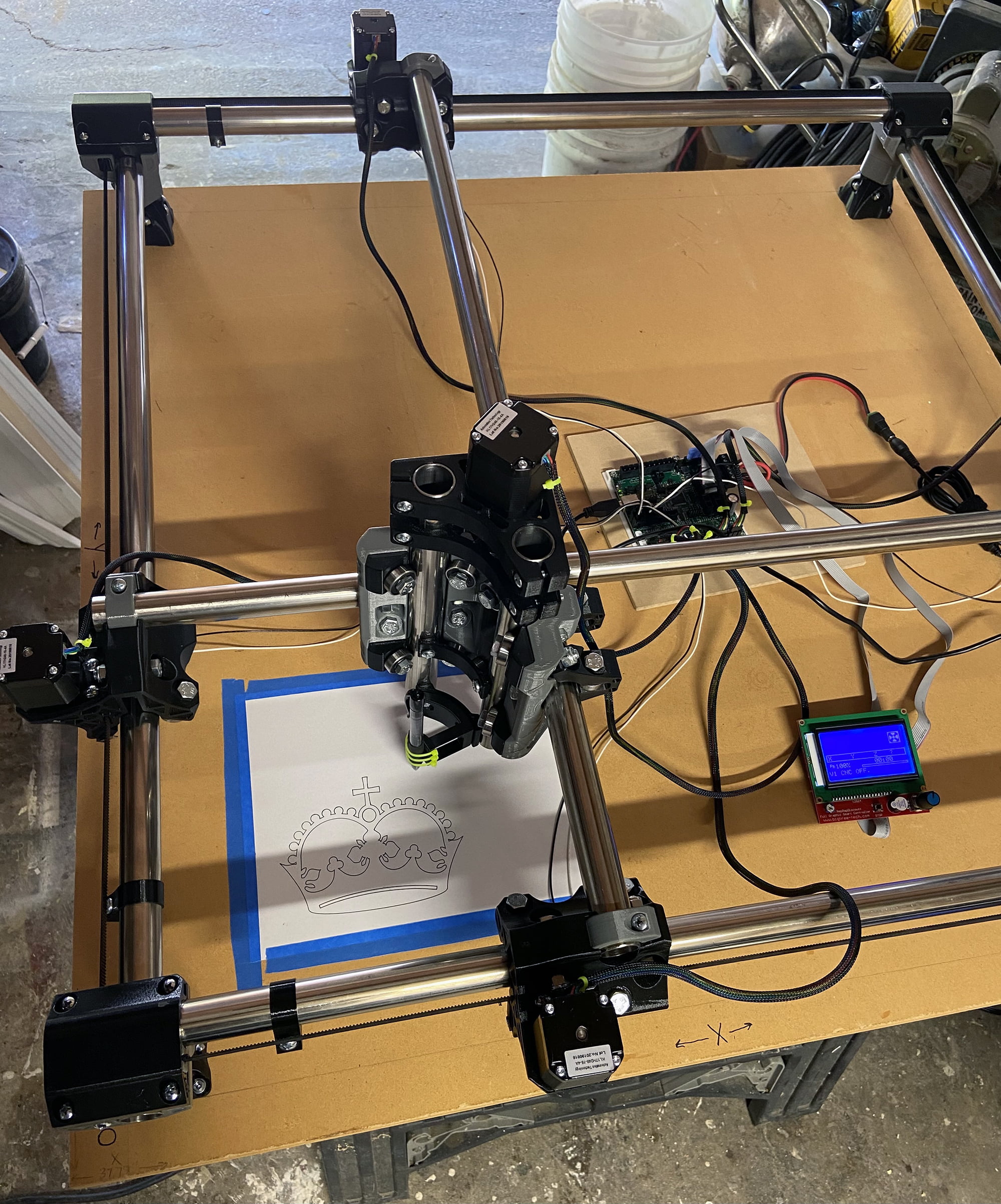
Finally made some progress on my MPCNC!
I’m embarrassed to say that I printed about 90% of the Burly a couple years ago and kept delaying the project. When the Primo released, I again took my time.
While I’m waiting to build my table, I decided to just dive in and start on a couple of sawhorses, aluminum plate (temporary support), and MDF.
I had some issues getting everything square but I had help from some people over on the unofficial prusa3d #cnc Discord channel.
Some questions:
How to check if my MPCNC is square after everything is assembled? Should I have it draw a square at the full length/width of my cutting area and then check the measurements?
Got Repetier-Host working on my Mac by setting 250000 baud rate, but I’m having issues running the gcode that I create in Estlcam. When I run it I get the error ‘Unknown command: “M3 S24000”’. If I comment out this line I have another error having to do with M140. Wasn’t really sure how to proceed so I just used Ryan’s 12mm/s crown test gcode.
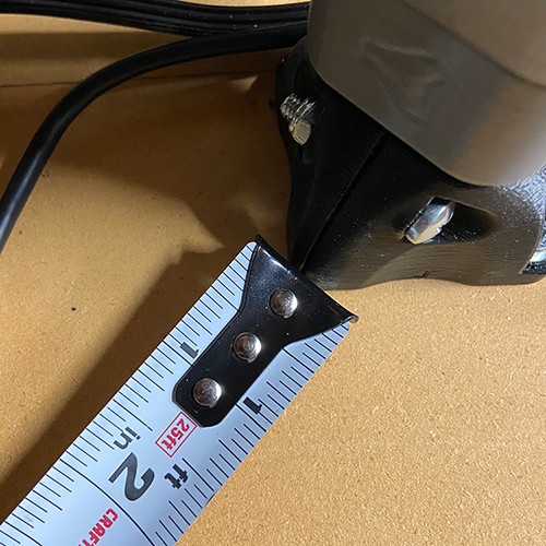
Still need to order endstop wiring kit (extension cables) but I’ve been playing around with that in the firmware. Perhaps I need to so some more reading, but how do I set the endstop stop blocks on my tubes? All I did was offset each stop block 50mm from the corner of each truck. Is that wrong?
Wire darryl: what the heck is it for? Only for setting the pulley position?
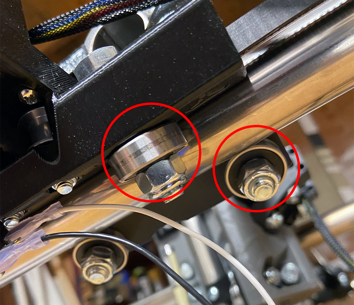
(EDIT) I noticed that two of the rollers on my front truck along the X axis do not make good contact. I’ve circled the problematic ones in red in the following photo. Seems like they only make contact in a small area near the middle. Is this common or is there something I should do to fix it?
First make sure the machine itself is square. Measuring the legs across the diagonals as per the instructions is the best way. These diagonal measurements magnify any errors, so getting them as close as possible is best.
Squaring the gantry at home position is next. With the dual endstops, you start with a tape measure and make sure that the distance from stop to end is as close as possible. Without, you can still use the stops the same way, just without the switches. From there, drawing a square isn’t a bad idea, but you really want it as large as you can get it. Again measuring the diagonals is the easiest way to check how square (or rectangular is ok) it is. If the diagonal measurements match, it will be good.
Yep. That is a good test. Before all the dual endstop stuff (and still some of us), we just hold the gantry up against some clamps or something when we engage the motors. Then you have a repeatable procedure to make it square. Checking it by making some corner marks (the whole rectangle isn’t needed) is useful, but only after you have something repeatable.
M3 is enable spindle and probably comes from estlcam. M140 is bed heat or something. That may be coming from repetier host, but it shouldn’t be there. The M3 shouldn’t hurt anything.
I am not sure I can answer the rest. I haven’t built the primo myself.
I set my stop blocks set so that the switch is triggered just before the truck hits its minimum position…and obviously the same distance on each end of each axis. Doing it this way maximized the working area, and also provides some protection for the switches if a mistake is made and your machine goes to a negative machine coordinate.
Something else must be going on. It should just ignore the m3 command.
Can you paste the first few dozen lines of your gcode?
Can you also paste the log?
I have a crazy guess, which is a common problem, that you have the wrong units set in the gcode file. It should say stuff like F600 for 600mm/min, or 10mm/s. I am guessing there is something like F10, which would look like it is paused.
For dialing the trucks and the core in I found the best way was to set my end stops such that the auto squaring got it perfect (measuring from the side tube to the appropriate gantry) and then adjust the trucks/core until the bearings could all be manually spun with a bit of drag on them. Worked out well for me at least.
If I comment out the 5th line and clear the log before running the job, I no longer get ‘Unknown command: “M3 S24000”’ obviously. However nothing new appears in the log.
The machine just does a travel move that appears to be at “normal” speed and then stops.
The Nxx and *xx are line numbers and checksums. They get added im to prevent noise from getting in the way so the firmware can validate the commands. The part in between are the actual gcode commands
Thanks for that info, I didn’t know that.
Any indication what is holding up the machine? Would it help if I posted screenshots of my Estlcam/Repetier settings or is this something that can be figured out if I post the entire GCODE?
Sorry, I don’t have any experience with editing gcode manually…just taking what my 3D printer slicer outputs
Sorry to make another post so quickly, but the fix is to DISABLE “Use arc commands G02 / G03…” in Estlcam Setup → CNC Programs
Somehow I missed Ryan’s third comment in the EstlCam Basics mentioning this. I was just going off the settings I saw in the screenshot, and someone on Discord pointed it out to me
Sorry to waste your time troubleshooting my bad configuration.
I’m going to setup some drag chains, but I have a question.
I read all over that you should not mount anything to the Z-axis, especially if you want to try machining aluminum. There is a nice drag chain mount that I found here but is that not recommended?
If not, what are other options for mounting?
Generally the recommendation is to connect to the core rather than to the Z tubes as connections to Z tend to apply forces that negatively impact the tool’s alignment to the work.