You the big boss what will work best is best. You tried next post 3000 inthe new fast and furious sweet and low 3 of 2020  does it get nitrogin inflated wheels
This one I get to build for me $$
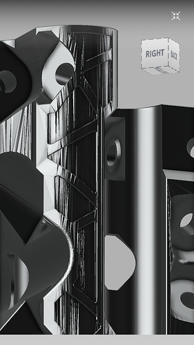
Yes. After the painful process of reducing the mesh with like a billion triangles into a mesh of around 45,000 triangles, so it was small enough for Fusion 360 to be capable of converting it to a body, to begin any type of edits with it. Needless to say, the surfaces suffered a lot of damage in the process, and repairing most of that damage took up the majority of my time in fusion.
I started by scaling the entire body 116.3%.
Moved the idlers 0.8mm closer to the belt slot.
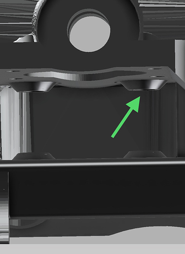
Resized the holes for the M5 bolts down to 5.3mm
I’m not positive on this but i believe i recessed both ends of all M5 holes 1mm to allow the M5x30 bolts to be long enough to allow full mesh of the nylock nuts. I’m pretty sure 1mm on both parts was enough on the corner tops and bottoms, i think i did the same 1mm on the trucks and both Z pieces and corner lock. May have been 1.5-ish. It’s been a while since i did those.
I also resized to 11mm for bolt heads and did 8.0mm for the nuts, and did a 2degree tapered extrusion.
To be continued…
I figured the tool mount would be fairly simple compared to everything else.
Import existing mount.
Make a copy of it. Resize the copy 116.3%
Smash the two together.
Cut off the useless stuff. Done.
The screw holes move out considerably and the stay out zone also increases.
No idea if scaling will solve much of that.
If you scale the blank, then cut your own tool mount out of it it will work.
Moving the center of the idler pulley holes over .8mm closer to the belt slot re-centers the belt in the slot… OR you could leave the holes where they are and use the 14mm (20T smooth) pulleys.
The pulley standoffs needed to be extended also to keep the Idler pulleys centered.
My CAD isn’t like that those are fixed numbers.
Probably not, but it does get nitrous. Make that two.
I see no need to do anything to the belt adjusters other than correcting the nut trap and belt gap sizes. The 16% wider belt slot won’t make no never mind.
The core would have only needed the T8 nut area re-worked, but the conversion completely wrecked the V1 logo and all of the nice “extra” detail. Many of the bolt head and nut surfaces got trashed also, so i had to do some major reconstructive surgery to it. I’ve got it to the functional point, but i’d like to clean up the cosmetics of it yet and hopes of printing it this weekend if the printer doesn’t hassle me.
I hope i’m as pleasantly surprised with the core as i was with the truck after I printed and assembled it, and it just rolled perfectly on the 1”emt.
What if you just used 1" EMT for the horizontal pieces and feet? Those are the biggest contributors the the cost. For z axis you can include the vertical 1/2" DOM pieces precut in the kit, without adding too much to the shipping costs…
IMHO Why are Europeans not asking for 30mm? Ryan has done a great job creating this project! The working area is easily scaled. Take it and do it!
I was interested in the possibility of milling soft material for specific projects. I now want to create a working area up to 1250mm by 650mm, in order to process a sheet of polystyrene. On the Z axis - 160mm! The frame will be made of 25mm aluminum tube, wall 4.5.
Perhaps this is not enough, but “don’t look a gift horse in the mouth”! If this is not enough for rigidity, I will cut it to an area of 650mm by 450mm. And I will process half of the sheet.
In any case, this entire assembly will be cheaper than buying a ready-made machine that can work this way.
Respectfully!
Or, replace the aluminum pipe with an aluminum stick? And the pipe only on the Z axis. In this case, the rigidity will be higher, but cheaper than a stainless steel pipe.
One, aluminum is not recommended because it is too soft.
Two, MPCNC may “easily scale” but stiffness drops quickly, and not just due to tubes (e.g. belts). This is especially true in Z.
Three, the LR2 is specifically designed for large format and performs very well at large sizes. There is not much need for extra-large MPCNC (but people build them anyway).
Can elox aluminum be used? But it is 2.5mm.
I saw a lot of buildings and good reviews about MPCSC on YouTube. For this reason, I decided to use it.
I will look towards LR. I need 160mm on the Z axis. Is it possible in the LR?
The price of an aluminum pipe 25x4.5 is the same as stainless steel 25x1.5.
Some calculator showed me that aluminum would bend less, so I looked in his direction.
Should we share some user print files as well? I could do so in one or two days when I have everything sliced and printed.
Point loads from the bearings will smash flats into the aluminum. Ryan has done it to stainless, which is quite a bit harder than aluminum.
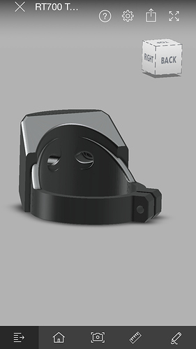
Just a quick 10 minute shot in fusion at the RT700 mount. Still needs holes re-worked and a little blending etc… but very doable.
After reading the discussion because of changing the tubing just my 2 cents.
First of all, a very big thank you, to Ryan. You are doing a great job and i want to thank you, also on the behalf of all users of the MPCNC and the Lowriders.
I could afford to buy a ready done machine. But i didn´t wanted.
It is a lot of fun to build, test and learn with your projects. It gives more satisfaction to me than only buying something.
You made a project wich, makes fun and gives people the possibility to have a cnc, who can not, or want not to afford a more expensive machine, or don’t want to buy a ready done cnc.
I can understand that someone is dissaponted not to get what he was waiting for. But…
If you have a small budget (i mean money or time), it is not smart to buy parts for a not existing project.
There can be a lot of reasons why Ryan could stop a project, or could not be able to finish a project.
Ryan is sharing his ideas, his experience with us. He and the comunity are giving support and he is asking for our opinions.
And all this for free. We don’t have to pay for plans or for anything else. If we want, we can buy in his shop, but we have also other options.
To be honest - what more can we expect?
I think we should see what we get from him and sould be grateful for it.
I can say that thanks to Ryans projects i started to think about, build and use a CNC.
Because of having a 150% time eating job, a wive and a small child i love, a lot of other interests and hobbies, i would have not started to build a CNC. Because of having not enough time, i would have not bought a CNC.
But thaks to this project, like a child who gets up in the night to play with his toys, i started to build an MPCNC while everybody was sleeping.
So thanks for the fun and the experience i got for my shortened nights.
Boy this started out as a simple answer to a simple question but…
1" emt if you must.
But with .065 DOM at $14.99 / 8 ft stick and .083 DOM at $17.99 / 8 ft stick (jegs.com), it seems like a lot of work for you to go thru for some guys to save what $20?
I know Jeff says to some guys $20 is a lot, and it might seem to be a barrier to entry, and I cannot disagree, money is money, and as I frequently tell my wife, saving money is just like making money.
But if you look at the difference in rigidity between 3/4" conduit and 1" DOM, It’s twenty bucks well spent in my opinion, and when you factor in the overall project cost and the overall expected lifespan of the unit you are building, it makes even more sense.
Now if someone can demonstrate that 1" emt is going to be significantly and measurably better than 1" DOM, then I guess Ryan has a lot of CAD work ahead. 
And I mean significant, to the degree that those of us who have printed material to support 1" DOM, to invest the hours and material to re-print for 1" emt. Short of that, stick with what is available and give Ryan some time off.
But bear in mind this is the perspective of someone who is on parallel builds of both at mpcnc and a low rider, because I believe both machines serve their own individual size range, and I don’t think either is a one size fits all machine.
There!


