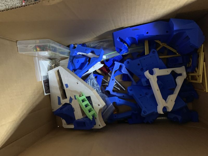
Been ghosting this forum for close to a month now, since the RMRFF show in Fort Collins, CO. Had been thinking about building a MPCNC but switched over to the LowRider after seeing the one at the show and talking to people at the booth. The sheet cutting focus of the LW fit my needs better. So been printing the parts and getting a box of goodies together. I am going to go with a 2’ wide x 4’ long now and once I feel like I understand CNC cutting better will expand it out to a full sheet.
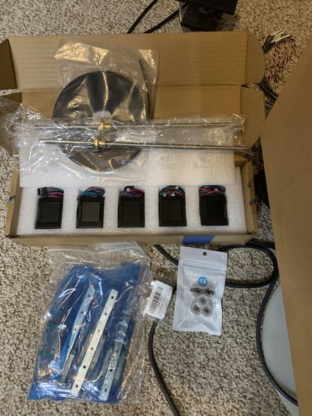
Have all the parts printed and waiting for an order of motors, rails and misc hardware to start the build. Going to go with the SKR controller, but need to wait till next month on that. Hoping I can get it mostly built in the mean time.
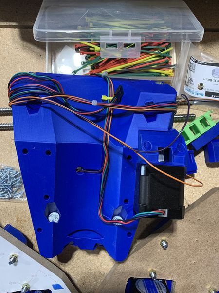
Printing that core had me puckered up for 34 hours. That was the biggest and longest print I have ever done. Happy that it completed first pass with no issues that I can tell so far. Will update as I move along.
I have an Ender 3 S1 Pro. I have played with that and the only way it fits is if I twist it 45 degrees and it is standing on edge. That is then a lot of supports and a smaller footprint to come free during the print, so had made me nervous to go that route.
I also don’t know that I have seen any of these plates printed. I think I have only seen them in wood.
Have others printed these plates? if so how did it go? Any tips?
I printed out the YZ plate plans 1:1 scale and with a bit of glue, jigsaw and some sanding I made the first plate out of 1/2" MDF. Still have one more to go. That was going to be one of my first projects, have the machine cut replacement plates.
Hey and welcome, I think it is nice to actually have evidence that the RMRFF brought some people onto the project MPCNC. It’s going to be a lot of learning and (mostly) fun, pinky swear!
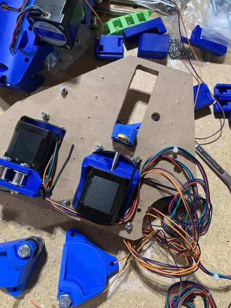
After going through what I have and comparing it to the build instructions it looks like I am still missing some items sadly. Working on getting those items in hand. A friend that went with me to the show has expressed interest in helping me with the build so working on getting a time scheduled with him. Hope to have some actual build photos soon.
A question for those that have built or are in the know on LW3 parts. Not seeing anything in the build notes that help, so asking just to make sure.
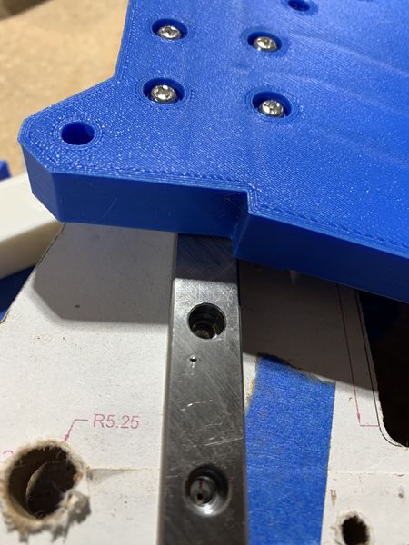
Is the YZ plate different on each side of the machine? or is it the same? I see PDF’s and DXF file that have this mirrored but the slicer file for printing it is only a single file. The mirrored files look the same to me, but maybe I am missing something. The build instructions also don’t seem to reference any kind of difference when building. I don’t want to make the wrong part and not find out until I am at the point of needing it in the build process.
The only difference (that I know of) is the side the 1/16 holes are on for the linear rail. If you drill them all the way though then it will work for either side
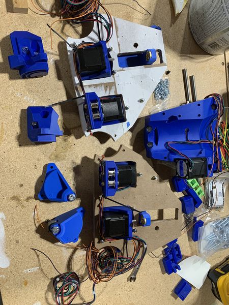
Hope to have these smaller assemblies built up into the larger frame this weekend. Have a friend coming over to help. I think the coolest thing on this build so far are those little slots for running zip ties through. Not sure why but those are just the coolest thing, props to whoever came up with them.
Did have one issue, but I think it will be ok. One of my linear rails has a nick in it. Sort of like a tool or such was dropped on it at some point. It came out of the bag this way sadly, no damage to the bag. I tried to take a file to it and think it is a little better but it can still be felt with my finger. It doesn’t seem to impact the block going back and forth, but will see when under load.
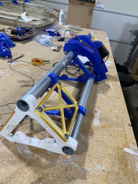
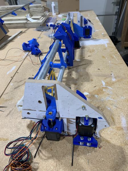
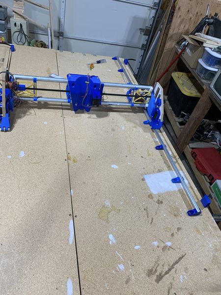
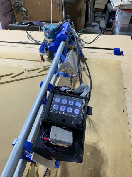
Was able to spend some more time this weekend and after some issues with my controller card have a machine that I can move around with the TFT screen controls. Still need to connect the home switches. Thought I had the hardware for that but it turns out what I have isn’t working, so waiting for amazon on replacements.
Been a bit since the last update, but there has been a lot of learning and work going on in the backend. This is all new to me and a lot of learning and struggles, but I am having success and things are coming together and starting to work and make sense. Woot Woot This forum has helped a ton to get me working and to this point.
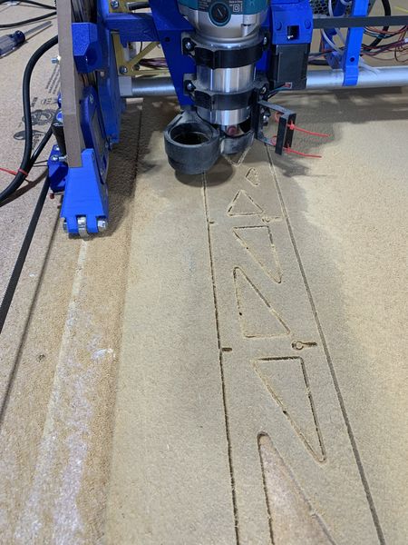
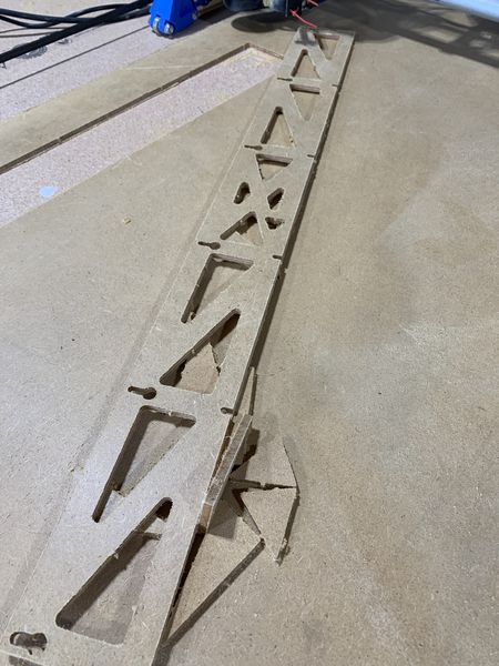
Here are some photos of CNC controlled man glitter being created, i.e. the struts being cut finally.
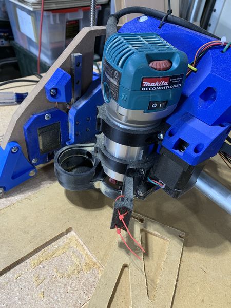
You can see my Z touch plate I had to hack together real quick on this last photo. Big chunk of aluminum but it works, just set the z offset correctly for the thickness.
When I rebuild the machine with the struts I am going to also replace that control box. While it does work I think it is too small for my shop setup. I can barely get all the cables into the case and get it closed up. It can also get a bit warm in the summer months and I want to have some cooling fans in the case. I have Design8Studios re-designed case printed and I hope that works better for me, due to the two cooling fans it can support.
These are really great! I installed 2 fans two, although I haven´t used them yet. My country seems to be colder then all of yours
looks like a great job. It´s a real touchplate!
I wonder, could you confirm if the one wire could be held against the Makita body (instead of clamping it to the bit) and if that works for probing?
Thinking of “upgrading” in time so I could do this.
Do you have a multimeter or some other continuity tester? Even an LED with a battery and a couple of leads will work. Check if there’s a connection between the metal body of the router and the bit (or collet, or whatever). My guess is no, since you probably want to keep things isolated, but I could be wrong (happens with uncanny regularity).
I can confirm that this does not work. The spindle bearings are held with non-conductive composite material. I recall seeing on the forum a mod where someone connected a ground wire to the spindle bearings. It may have a deleterious effect on runout if you aren’t careful.
ohh damn. I had seen this in some video of Shapeoko users where it worked. They could just clamp one side of the sensor cable to the metal router holder, and the other end below the bit. Maybe it only does so on specific revisions.
Hoped to improve my touchplate set up. But this will be a no go then. Anyways, thanks for confirming !
looks great! I’m hopefully not too far behind you with my build!
I just did glorious battle with my linear rails to make sure they were well aligned. They refused. Calipers said they were fine, and I realized it was where I had the plastic “car thing” anchored to the aluminum plate that was wrong.