My only single-flute 1/8” bit (1/4 shank) only has 19mm cutting depth. Even with bits having 1” flute length (2 flute) I’m still having trouble getting all the way through 3/4” (20mm) material.
Is outline cutting typically just the bit’s width in multiple passes, or is there a better way?
Seems like I once accidentally set Fusion to do a finish pass after every rough pass on the outline cut – slow, but that might be the best way to create a slightly wider path for chip ejection as the depth progresses.
What thickness of ply are you cutting? Those bits have 17mm cutter length…
For now, I’ve gone ahead with Plan B: run my stock through the planer. Total thickness doesn’t matter for this project as long as it’ll handle the contours. Trying 5/8” in the maple on the next run.
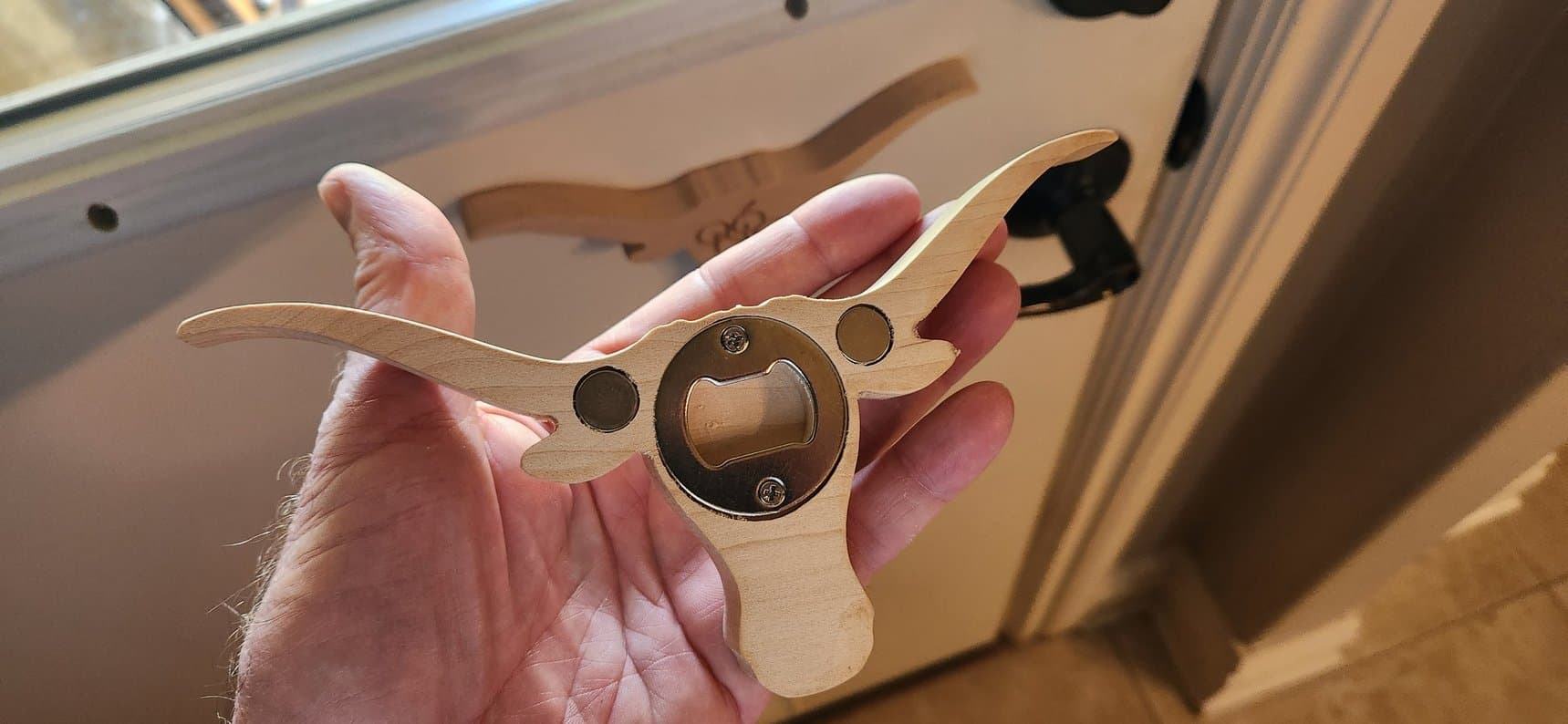
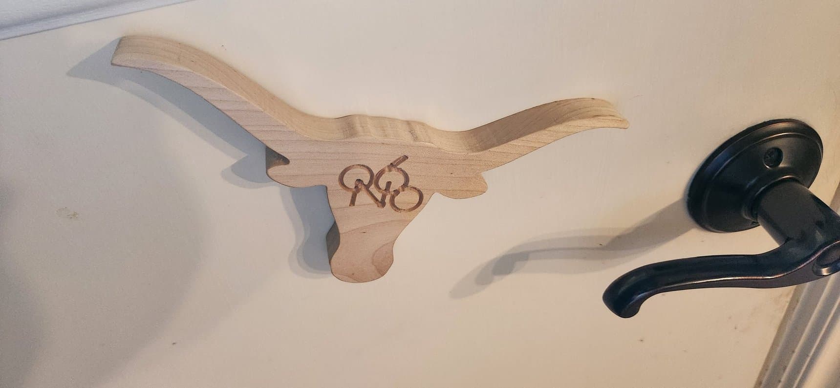
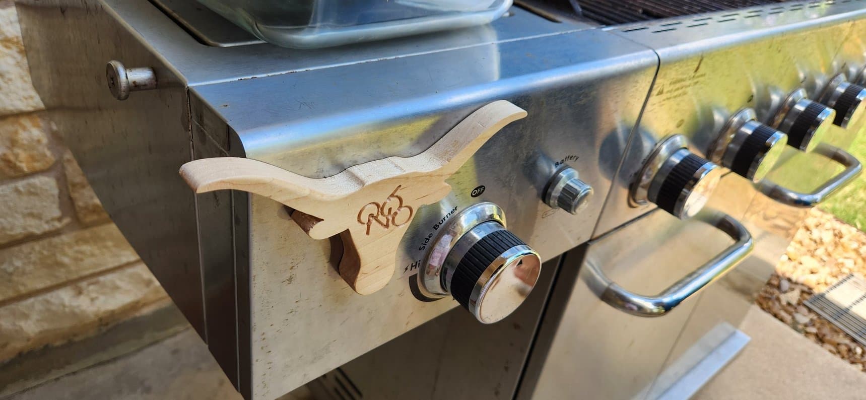
Well, the birthday weekend in Austin, TX was a success. I was up until about 2am Weds night making my last cuts, but here’s the final product. My buddy was turning 60 and he’s a University of Texas grad (“longhorns”). I had drawn up the “QN 60” emblem (his initials & age) in Fusion360, hoping I could get the laser working that I had just bought from @Neilp, but if you’ve read the above, I had enough else to deal with. Then for the longest time I couldn’t any suitable CAM to generate in Fusion – those lines are 2mm wide; I was essentially trying to generate a v-carve for a 30 degree V bit. In the end, this is the best I could do with the time I had. My goal of bringing enough to have “party favors” for all was cut back a bit; I think I ended up with 5 or 6.
I’m starting to understand the importance of machine stiffness.
I started playing with box designs from makercase.com, and the first design I started on was a symmetrical 4-chamber, open-top box. Knowing that getting my clearances right was crucial, I started by only cutting the two divider pieces with mating half-slots. Way too tight. Using Fusion’s CAM, I set my “radial material to leave” to a negative value and kept incrementing it until I got two parts that could slide together. (Alternatively, I could go back to makercase and increase the material thickness.)
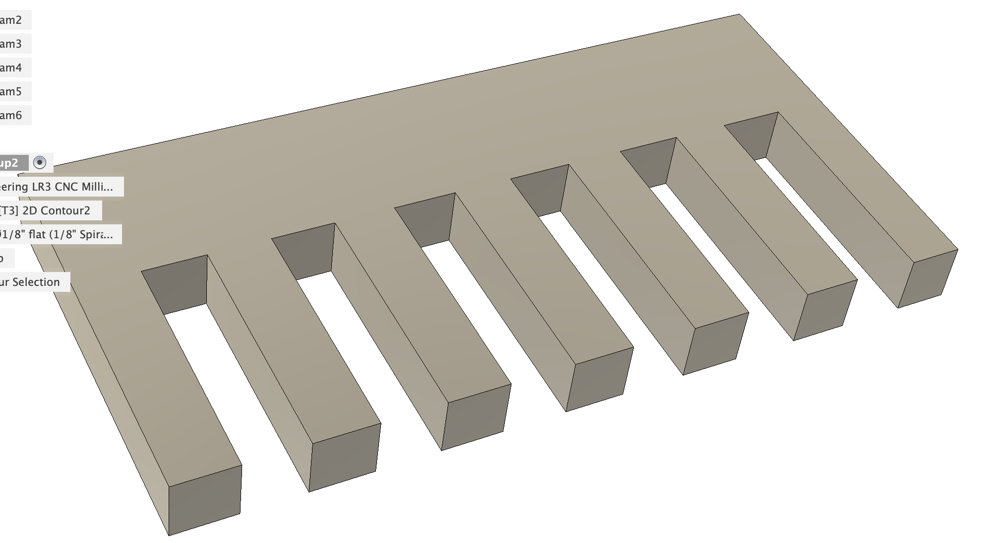
Well, then I decided to do my own test to see just how much clearance I should need to add. I’m using nominal 1/2” cabinet ply (actual 0.463”), and I created the design shown, where each slot gets incrementally wider. Then I could test to see which slot would accept another piece of my plywood. I started with slots having zero up to five 0.1mm increments, and even the largest slot was kinda tight. I changed the increment to 0.2mm, so in theory, the largest slot would be a full 1mm oversized.
They say that the difference between theory and reality is that in theory, there’s no difference at all. But in reality… there is.
As it turned out, my largest slot that SHOULD have been 1mm oversize was virtually the same as the actual plywood thickness. In other words, between me setting the CAM to use climb cuts, and the inherent flexibility of my machine (I don’t even have my permanent struts on), I’m getting a deflection of about 0.5mm, which compounds to a full 1mm on both sides of a slot.
Maybe I’ll take a little time and start installing some of those struts. Seems like the bottom one might have the greatest impact here; it certainly would be the easiest to install.