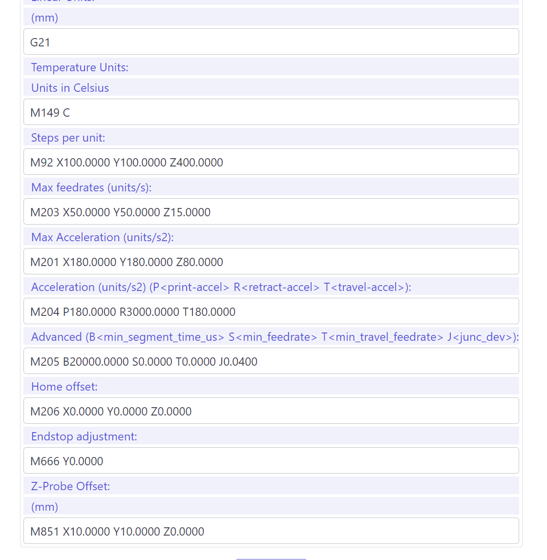
@tjones99 . Ok so I opened the marlin file I had initially uploaded and saw that it had some tmc driver defined in configuration.h so I changed that to A4988 (this is what I’m using) for each of the axis and re-uploaded the firmware to the board. I don’t think much has changed though (at least from what I could check through the Wi-Fi software–I’ve attached a screenshot of these settings, but I’m not sure if this is what you were referring to or not), and now even the x-axis is struggling to move again. I don’t know if this is a hint that the problem is firmware, but its slightly strange that both parts seem to move ok when I apply a little force myself in the direction of movement.
Came back after writing the above, thank you because your suggestion helped find the root of at least part of the problem and long term is helpful anyways, but I looked into tuning the current on the drivers after this and i seem to have found the root of problem! Presumably they were set too low or something as i have adjusted them all to allow the correct current. Or at least as close as i could get it with a vref of 0.8 volts, this was the maximum I could get although the equations online suggested it should be 1.4, to be honest i don’t full understand it, but my motors seem to have a relatively high current rating of 2A.
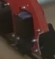
Now while all my motors are now running a lot more smoothly and y seems to run ok at 600mm/min at 1200 sometimes one side seems to get stuck/not move? It’s not rlly making as much as a ground sound and mostly just moving so that it’s wildly un square because one side moves while the other is stuck, but the side getting stuck alternates randomly. Its happening to each side separately and randomly so I don’t think its a loose wire issue and with a little force in the right direction behind it it runs smoothly so i think it might be mechanical but again i’m surprised its happening to both sides because i dont see that the non bar side could have anything to catch on? I will try an attach a video tomorrow showing the issue if I haven’t got it solved by then
Shared ~1min clip showing crude Y motion tilt test to help rule out mechanical cause(s).
I tried my best at this test after I sorted the electronic side out, and it seems stiffer/less smooth than yours did. I don’t know if this might be contributing to the problem or not, but any recommendations on how to improve it would be appreciated.
Here is the video:
In response to your question @azab2c I bought the motors through the amazon link provided on the v1 engineering instructions, but this is the link to the specific model that i could find:
You also reminded me that I should probably improve the ventilation for the circuits, as currently its not great, I was slightly worried though about debris from cutting getting in and messing up the electronics though, is there any suggestion you might be able to provide regarding this.
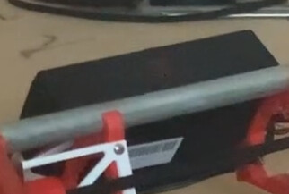
Your black Y rail/pipe looks nice.
Ha. Thx. Was struggling to find a good pipe for the project as there isn’t rlly hardware stores where I live, but chanced upon a perfectly sized curtain rail in ikea one day and it works quite well.
@Steven_Willems
Also think bad connection of the stepper connector at the board.
In regards to this and Terry’s previous mention of this, I will still check the wiring anyways as I noticed I had some dodgy wiring causing one motor to not work great previously.