We were literally typing the same message haha
1 Like

@Bret_Martineau
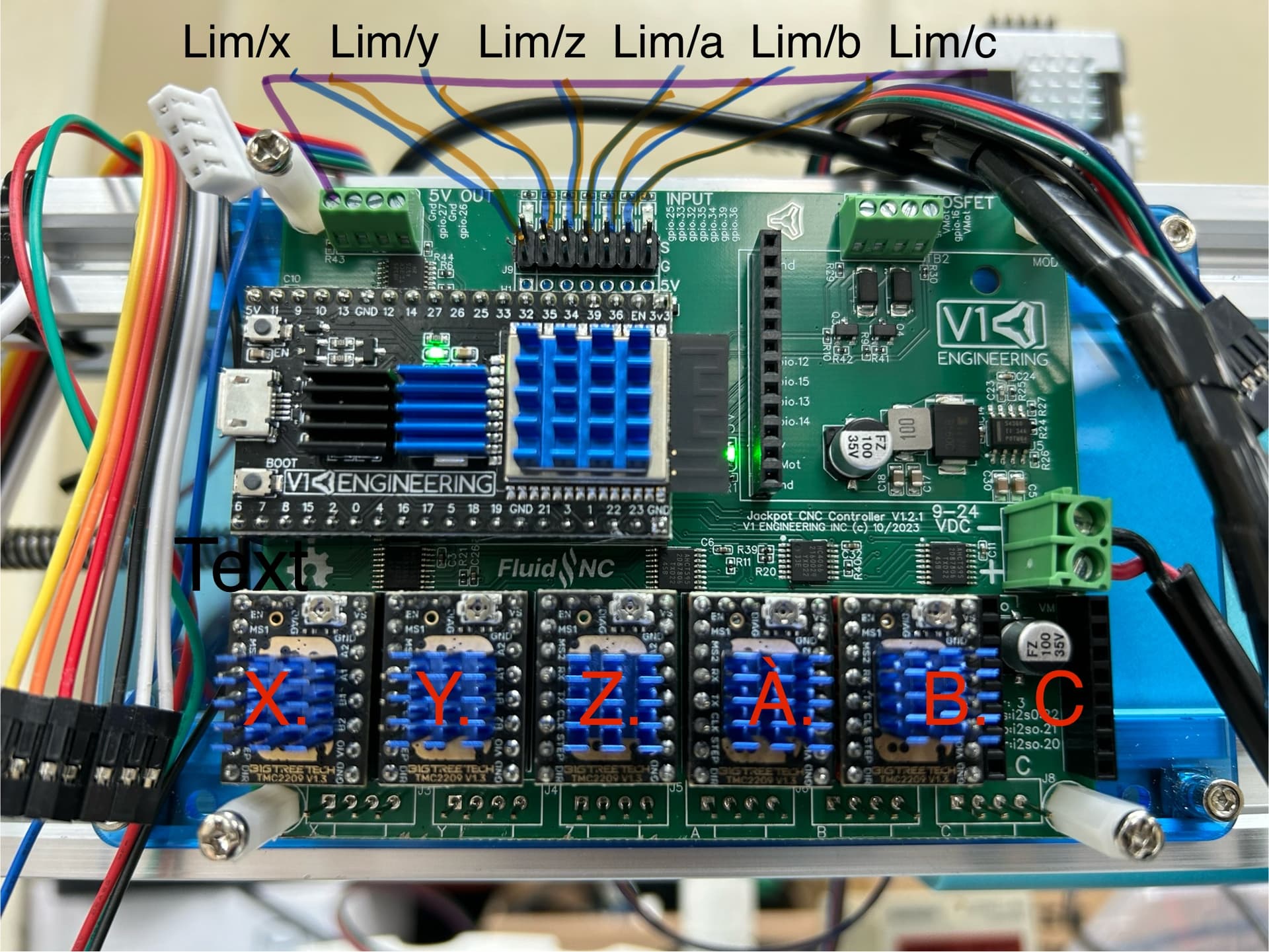
The pins you have labelled as “Lim/X” (and Lim/Y, etc) are typically used for end stop switches and the last one typically used for a probe. I don’t know what “Lim” stands for. ???
EDIT: well, I feel sheepish. “Lim” probably stands for “Limit switch” which is just another name for what we call end stop switches.
1 Like
Assuming your wiring is correct, and your power supply is either 12V or 24V, and you comment out the “C” section, you should get movement. Using the WebUI via wifi is a great way to confirm movement. It’s suggested to use small increments for testing.
1 Like
yeah. limit switches.
I highly suggest you start over and use our standard yaml, nothing should be changed. From there when everything works we can help you add a driver.
1 Like
Something as little as an extra space will ruin the config.
2 Likes
Also I guess I should ask if these boards have a different pin out for the stepper cables. or are the wired like every other controller board?
He’s using the Jackpot for some factory type automation machinery, and he needs one driver per axis. When he ordered the board, he got the firmware for MPCNC, which as you know has two steppers per axis for two of the axes. I edited a config file to put one stepper per axis. At first I made the mistake of basing it on my older LR3 Jackpot config file, but I just now edited another one based on your much more recent Jackpot config for MPCNC that you sent him pre-flashed. He’s not trying to add a 6th driver right now, so the newest one I uploaded does not have a 6th stepper section yet. I edited the post above to switch in the newer config file. Hopefully this newest one works for him.
This is good advice TMC2209s are really affordable and quite good. Having all six the same is much better than trying to mix driver types.
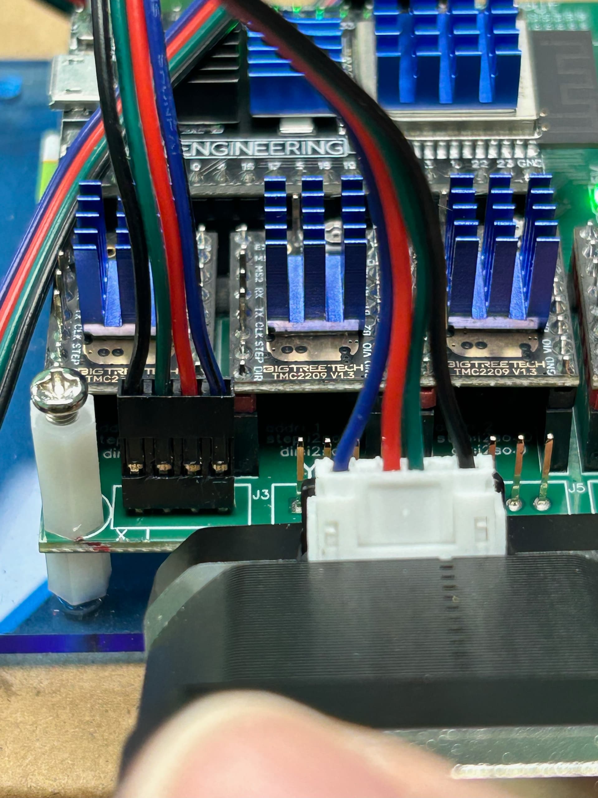
Same pinout on Jackpot as most 3D printer controllers.
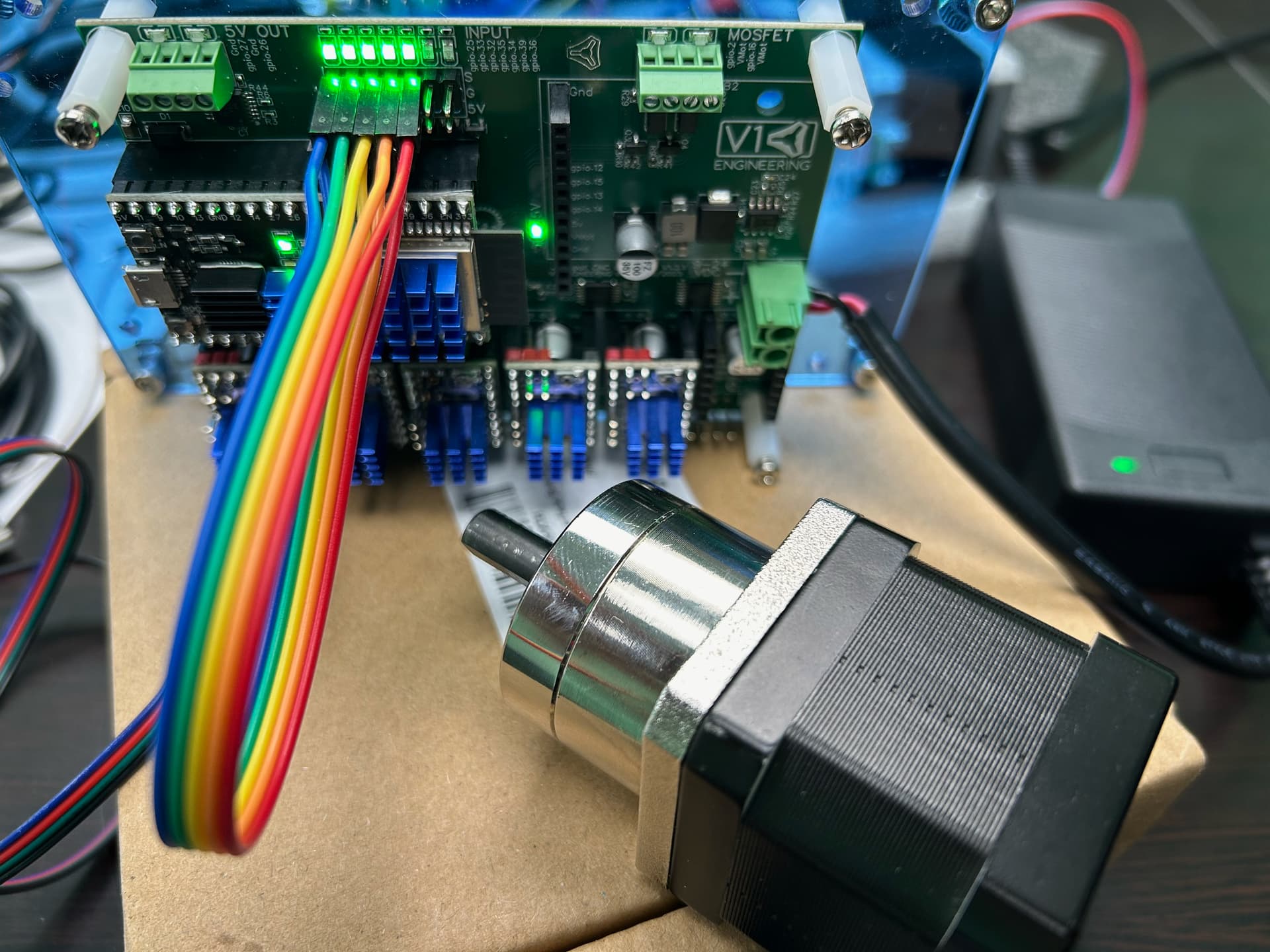
But not all steppers are wired the same, so it’s always worth doing a motion test with at least one stepper on a bench before wiring up the whole machine.
Be aware that FluidNC treats A/B/C as rotary axis, which means they’re unitless. This is mostly knowledge you’ll need for you CAM or when writing gcode for the setup, and is a FluidNC thing not a Jackpot thing. All FluidNC systems are like this.
Since configs have been modified, the next step will be to make sure you’ve got a good FluidNC boot with your starting config. We need to see the output of $SS to check that.
I’m not sure I follow, the Jackpot electrical design assumes you wire each microswitch endstop across the headers provided. I think that’s what you mean by drawing a yellow and blue wire going to each endstop.
You don’t want to mix the 5V GPIO into the endstop wiring.
What are you using that 5V GPIO for?
Are your endstops microswitches?
Have you tested them individually to verify they are detected properly by a running FluidNC?
OK, to all the guys here who are more expert than I am (which is not at all) when it comes to steppers:
Help needed.
@Bret_Martineau is saying via email that his account here is too new to be allowed to post the media that he is trying to post, so I am going to post it for him. He’s got a Jackpot and he temporarily jumped the end stop pins, and he has tried various stepper motors, but has not gotten movement, except for strange stutter.
Here are his pics and video:

The switches are proximity switches so they have a 5v input.
The reason for asking if I can use a DRV8825 on the C is because I have several here already and would not need to wait on delivery before moving forward.
Also it is an axis used to operate a clamp so there is not need for it to before perfectly in step sync with any other axis. It doesn’t need to micro step and It is an independent axis not constrained.
X -/+ gantry movement
Y + turret rotation
Z -/+ up/down cap holder
A - capper rotation
B + liquid pump
C -/+ bottle clamp. keeps them from spinning as the capper spins the cap on.
The limit switches will be used as such. And keep in mind the switches will be used more for an “out of tolerance” alarm than an end stop. They will be 2.5mm from activation at all times to keep the machine from wondering slightly and missing the bottle etc.
X switch for the x end stops
Y switch for the y end stops
Z switch for the z end stops
A front doors
B side door and rear door
During testing I have all limit switches jumped so they are staying closed. I also tried pressing home for each individual axis and activating each limit switch/jumper so the machine assumes it has a positive. That didn’t change things. Still no movement.
The board is sitting on my desk for these tests. I have several different stepper motors I’ve tried and they each work fine pinned how they are in three other boards (2 running mach3 and one grbl) and I’ve checked the pin out in a couple of them with my meter as well. Nothing different between them.
We need a schematic from you. The default config is likely wrong for those proximity switches.
We also need to see the FluidNC output as requested above:
The switches don’t relay 5v back into the board. The 5v is for the magnet in the switch that detects the metal plate opposite it.
However for the time being they aren’t in the equation at all because I have the limit pins simply jumped to themselves so the proximity switches are not actually wired in.
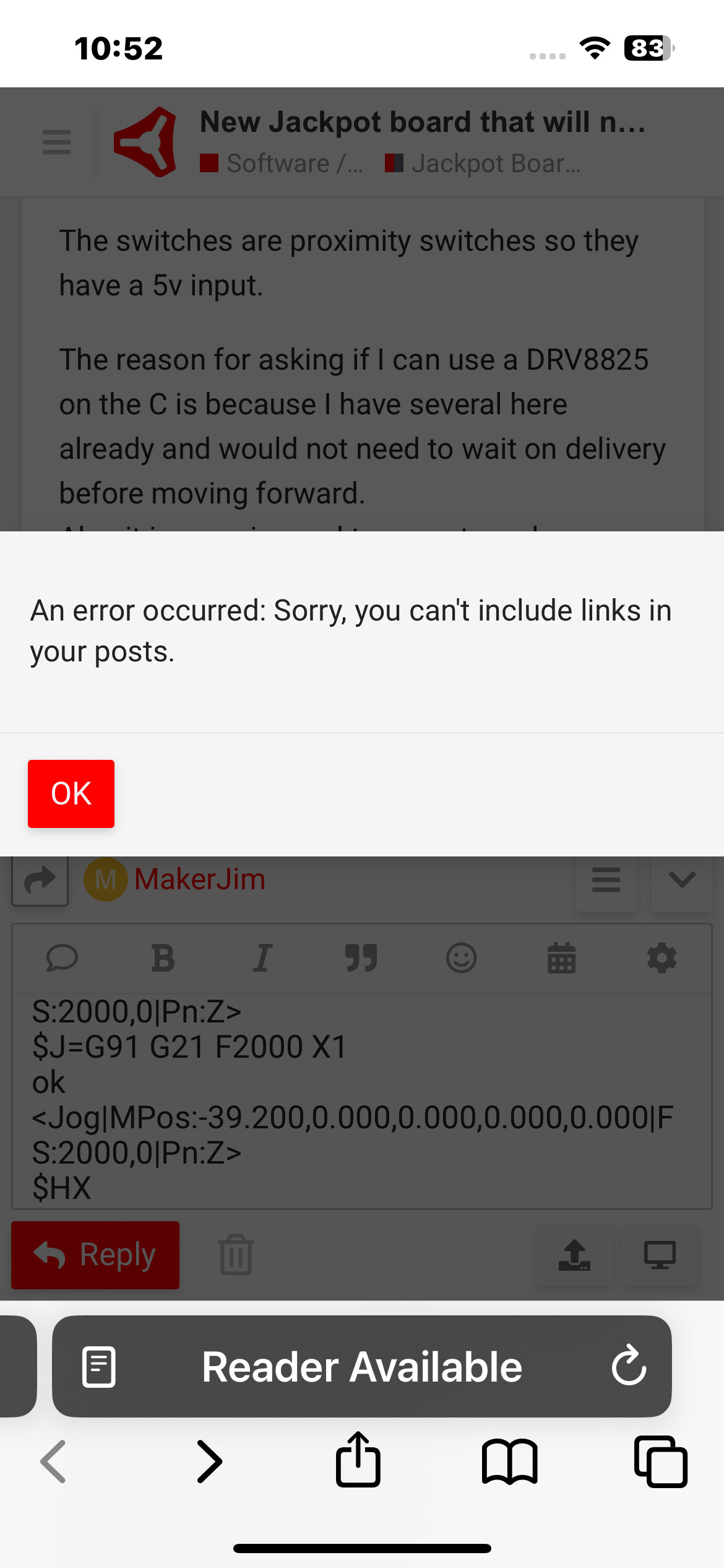
When I attempt to post the $SS I get a warning that it will not post because it contains a link. I removed what seemed to be the issue from the $SS and got the same notification.
So I sent the $SS to Doug who didn’t see anything unusual in it.
I’d rather do all this on the forum but it won’t allow me to post videos, links etc because I’m a new user it it says. Which is true but that certainly is making it a little more difficult. I do under It’s to keep spammers out etc so not complaining just stating what’s going on.
I have run the machine on Mach3 with 2 boards synced with macros for all the needed motion but I truly think that FluidNc and this Jackpot board are the better alternative.
It’s seems more than capable from what I’ve read so I’m really wanting it work.
1 Like
Provide the part number or better, the data sheet for the proximity switch. It’s very unlikely that you have an electromagnet with a reed switch, and the way to avoid confusion is to do the systems engineering right up front. That’s the data we need.
I understand you have them jumpered, but this will be something that needs to be addressed.
That’s got to be really frustrating for you. It’s also really frustrating to not be able to help you.
Maybe @vicious1 can help lift the new user restriction. What’s your order number?
We really cannot do this via email, so someone saying they “didn’t see anything wrong with it” is no help because we can’t view it with our own eyes. Even a seasoned user like @DougJoseph.
They likely are- but it means we need to be able to troubleshoot in the open.
Hopefully we can get your new user restrictions lifted to make that possible.
Since we know Bret’s a real person and not a spammer, is it possible to waive the spam protections for him?
He mentioned that he’s blocked when attempting to post his $SS outcome - site thinks it has links.
Tried posting a pic of the wiring diagram for the proximity switches but no dice.
Long story short they are a switch I’ve used successfully before and they wire in as such.
Brown wire to positive 5v-30v
Blue wire negative (gpio)
Black wire to load (pgio)
It’s an inductive proximity sensor N/O
But for testing purposes they have been removed from the equation entirely. They will need to be accounted for in the config moveing forward once the machine will move.