Hey All. I’ve posted a few questions on here to get some help, and thought that I would contribute back by giving some details of my build and a few things I found along the way (and some other questions that I still have!) - Apologies for the very wordy post but I didn’t take many photos of the process!
Physical Build Process:
- I went with just the default sizes (450 x 330 x 81mm) from the calculator. One thing I want to dabble in is carving small acrylic/MDF mounted neon signs, so a massive machine wasn’t needed. Also my first proper foray into CNC so thought I’d play it sensible.
- I went with the standard 25mm steel conduit, but I found (at the time at least) a cheaper source than Screwfix which was GSM Supplies (https://www.gsmsupplies.co.uk/conduit-galvanised-25mm-3m-dt25300.html)
- I haven’t got many power tools for cutting large pieces of wood for the table top, so I found a place in the UK (justmdf.co.uk) that does custom cut MDF and plywood. I decided to get a few 12mm MDF Spoil boards cut (without the holes) and a 12mm plywood table top to build the table.
- I built a standard table just like it’s shown in the docs, although at the moment there are no legs attached and so it’s simply a table top on the spare bedroom floor. Wickes had 2"x4" in stock and delivered at a reasonable rate, although they were a little warped. I initially tried to create stronger table joints with overlap joints for strength, but trying to cut accurate overlap joints using just a mitre handsaw proved to be a bit of a pain (if only I had a working CNC machine…) so I gave up and just butt jointed and screwed them instead.
- The table top I had cut to the exact measurements popped out by the calculator (720x610mm) to match the outer feet, but I wish that I had added a few cm overhang either side as the CNC feet are right at the edges. I also haven’t cut out the spoil board on the table top, but I think that all this means is that the 12mm spoil board will sit on top of the table top, in effect reducing the Z height from 81mm to an effective 69mm - not too bothered about this as I’m yet to cut proper stuff still…
- I used countersunk screws to attach the feet as at the time that’s all I had, but now I wish that I used Pan head screws. The Counter sunk screws don’t quite fit flush in the plastic leg mount holes which I think Pan Head screws would. Either way, I’ve got enough bite from the screw into the wood and it’s holding the legs well.
- I purchased a pretty nice Milwaukee hacksaw for cutting the pipe. Although it went through it very well, it wasn’t quite perfect and needed quite a bit of filing. Instead I bought a pipe cutter and although more effort it gave much better results…
- Building the legs, feet, and corner bottoms were all pretty straight forward.
- Building of the trucks was pretty straightforward, although setting the truck tension was confusing. I found that when tipping it at 45 degrees, it’s easy to know when it’s too loose as the truck will shoot off, but I couldn’t get it to simply move “slowly”. In the end I got it so that at 45 deg it would only move with a little shake, and then would fall off but not too fast. Would be great if someone made a video as to exactly what it should be like
- I decided not to add the Endstops at this point (mainly because the endstops I had were of a different type and the screws didn’t line up). This luckily allowed me to solder the endstop wires and then screw them on to the trucks - which I think might be a less awkward approach.
- I had a few issues with the Core and the clamps - whereby the bearings were not fully touching the rails and the core rails were too loose, and I couldn’t make it tighter. Luckily I found Ryan’s post here (Loose Core - #7 by vicious1). The fix was to take the clamps off the core, add the bearing and the bolt and clamp it all the way first, and then add the clamps to the core. After I did this, I found that all the bearings were then engaged and I could tension the bolts again.
- The Z-axis was a right pain in the arse for me. Not having a bench drill, or even knowing whether the drill bits that I was using for my Makita drill were proper metal drill bits, I found the drilling of the holes tricky. Measured the hole centres, and then used a hole punch to hammer a dent so hopefully the drill didn’t slip. Drilled slowly, and used some WD40 as some cutting oil and it eventually worked. Unfortunately, my top hole on one rail didn’t quite line up with the bottom one, so had to drill a slightly larger hole to fix it - found it really difficult to fix a lopsided hole in a metal tube! A lot of filing and made it into an oval that works ok. An actual clamped work bench and a better metal cutting drill bit would have been nice here!
- Rest of the physical build went smoothly and the squaring seemed ok - so maybe beginners luck here!
Electrics & Wiring
- As mentioned above, I found it way easier to solder the endstops first, and then mount them to the trucks. If I had mounted them to the trucks without soldering, no idea how I might have accomplished this after.
- I bought the "17HS19-2004S1" stepper motor from Amazon / OMC Stepper Online. The standard stepper motors came with a 1m cable, so I extended these with 22 AWG wire. Not sure if it’s the correct way, but I snipped the wires in the middle (so I didn’t have to worry about re-crimping dupont connectors), stripped about 1cm off the ends, then twisted one end around the other so they kind of fish hooked each other, then twist as much as I could on each end. Soldered the middle, then heat shrinked. Oh and don’t forget to put the heat shrink tubing on before you solder the crimped connector back on! (which I obviously did once…)
- For crimping ring terminals, I initially bought this (https://www.amazon.co.uk/gp/product/B0C5MGWLLT/ref=ppx_yo_dt_b_asin_title_o08_s00?ie=UTF8&th=1). Crimping ring terminals was pretty poor, but the automatic wire stripper on it was very nice to use and made it much faster and consistent than other ones I used. For the crimping I instead had to get this Iwiss/iCrimp one (Amazon.co.uk) which worked perfectly. The added bonus to this was that it already contained a set of jaws to do Dupont crimping.
- For the crimping of dupont connectors I found it easier to pre-clamp the connector in the ratchet jaws, and then carefully slide the cable in. Trying to add the cable to the connector, and then crimping I found much trickier.
- I sheathed the stepper motors so it was all nice and tidy, then realised that I could have addded the stepper motor wires at the same time in the same sleeve. Doh! Instead had to zip tie them together as I really couldn’t be bothered to redo it all and buy more PET sleeving. 6mm sleeving worked perfectly here.
- I then cable tied the wires to the side of the tabletop using these (https://www.amazon.co.uk/gp/product/B08RSFZ6TT/ref=ppx_yo_dt_b_search_asin_title?ie=UTF8&psc=1). Made sure there was enough slack for when the gantry moves and it seemed to get the wires out of the way a little. Z axis stepper cable was routed through the middle tube, and zip tied to the top of the truck nearest the rail where the cable goes in using a sticky zip tie. Again not perfect, but it doesn’t snag so far.
- I’m using a Duet 3 Mini 5+ WiFi board. All steppers connected into the board the same direction and all the A+/B+/A-/B- wires lined up correctly with the pins on the board. Motor direction is then controlled in the config.g file. So I have X → Driver0, Y → Driver1, Z → Driver2, X1 → Driver3, Y1 → Driver4. Endstops are connected so X1 → IO_0, X2 → IO_2, Y1 → IO_1, Y2 → IO_3. For connecting the endstops only the “GND” and “io0.in” pins are used on the dupont connectors, so NC->GND, and C → io0.in. The IO ports on the duet have a lot more pins but they are simply ignored.
- I’m yet to hook up a Z Probe, and at the moment my homez file is simply doing it manually. I’m only messing around with pen plots at the moment so it’s not a requirement yet.
- Once everything was connected, I tested the motors and directions first before homing. I moved the gantries to roughly the middle, switch the machine on, and then in the Duet dashboard, I issue an “M564 S0 H0” command which lets me skip homing. I then jog each axis +1mm and -1mm just to make sure that I’ve got the motors going in the right directions. On first boot and config I had the +1mm jog going towards the 0,0 origin, and same with the Z axis in that a + jog command would move the Z axis in the wrong direction. So a quick switch off and flip of directions in the config solved this.
- The Duet Dashboard also has a plugin section for Endstops that can be downloaded. This allowed me to quickly test each endstop to make sure it fires and registers on the board. Had a problem with one switch having dodgy dupont crimp that had to be redone. I think there’s a command to get the endstop status, but having this little dashboard plugin helped immensely.
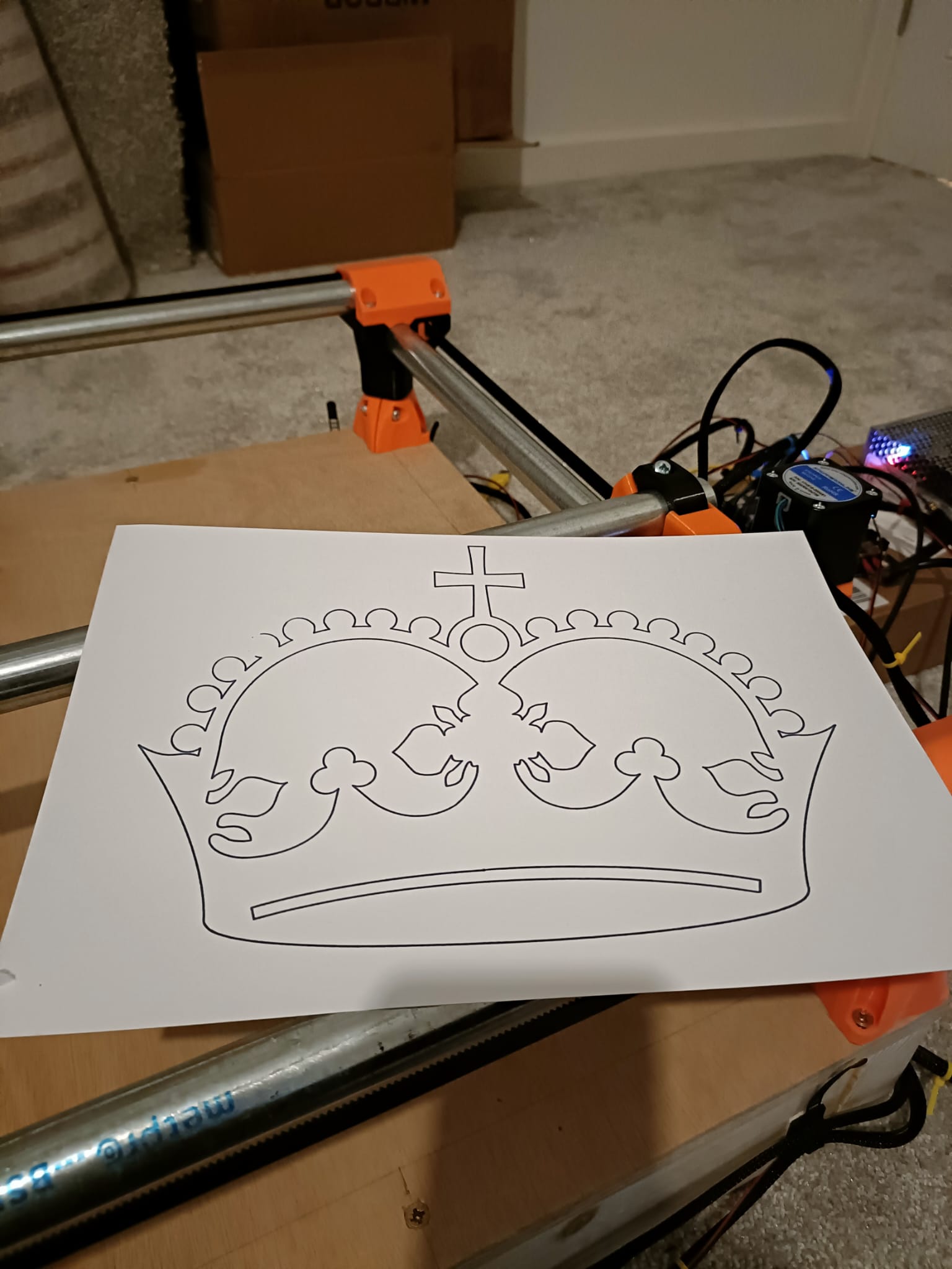
Test Print
- Below is a photo of the first crown test print, which I think came out pretty well. In the top left corner there’s a few faint spots where I think there’s a bit of a dead area in my table. This shouldn’t be much of an issue once the spoil board is added.
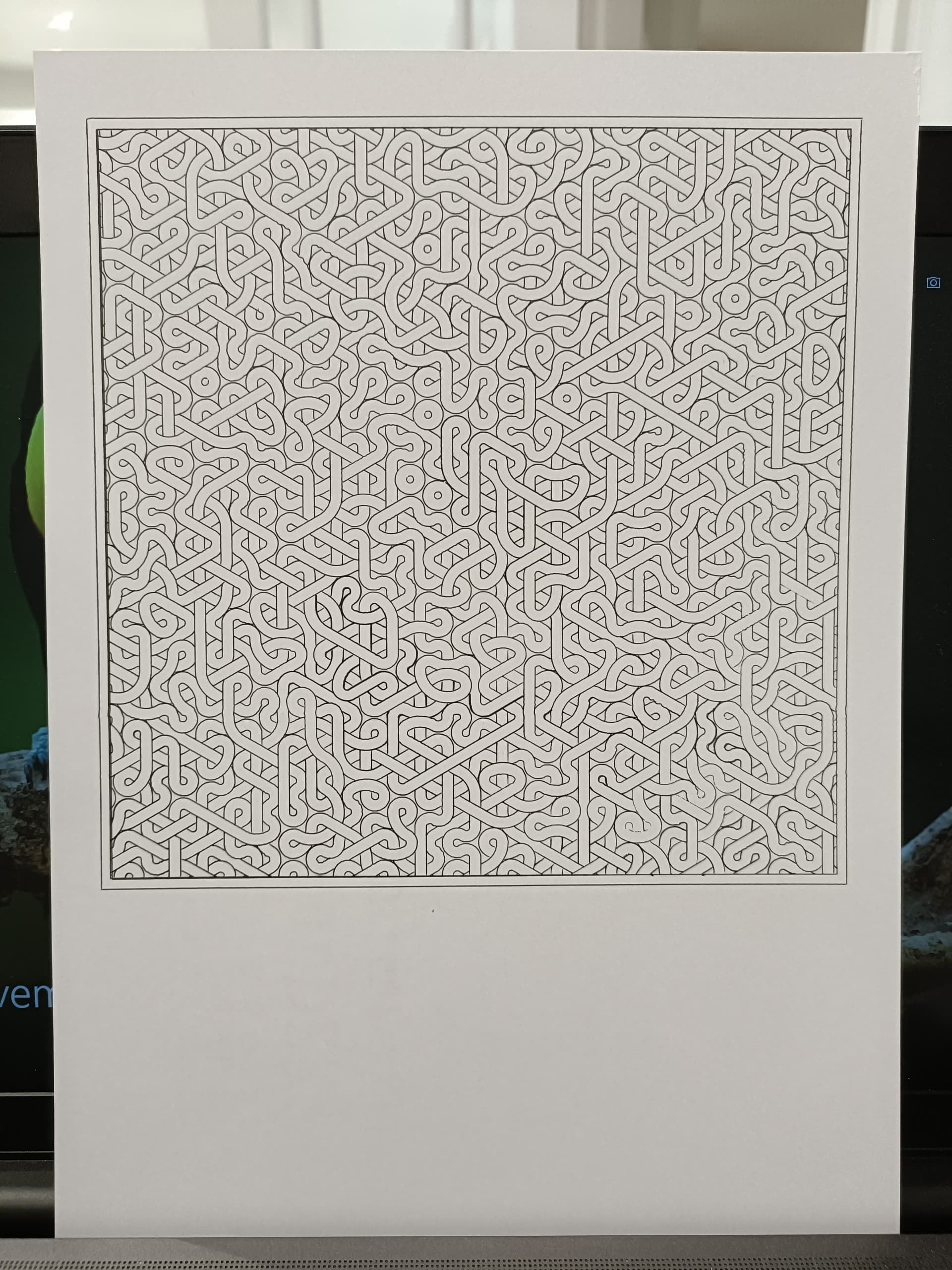
- I then found a much more intricate design pattern and decided to print it out using a fine pen. I was pretty impressed with the whole accuracy of it all, especially when I repeated the pattern to go over some lines and it was spot on.
Here is my Config.g:
; executed by the firmware on start-up
;
; generated by RepRapFirmware Configuration Tool v3.3.16 on Thu Nov 02 2023 14:14:44 GMT+0000 (Greenwich Mean Time)
; CREATED by COOP
; General preferences
G90                                             ; send absolute coordinates...
M83                                             ; ...but relative extruder moves
M550 P"CoopsCNC"                                ; set printer name

; Network
M552 S1                                         ; enable network
M586 P0 S1                                      ; enable HTTP
M586 P1 S0                                      ; disable FTP
M586 P2 S0                                      ; disable Telnet

; Drives
;Drive 0 (X Motor) = X
;Drive 1 (Y Motor) = Y
;Drive 2 (Z Motor) = Z
;Drive 3 (E0 Motor) = X1
;Drive 4 (E1 Motor) = Y1

M669 K0                                         ; explicitly set Cartesian kinematics, even if I should not need to

M569 P0 S1 						; Drive 0 goes forwards		-  X
M569 P1 S0						; Drive 1 goes backwards	-  Y
M569 P2 S0 						; Drive 2 goes backwards	-  Z
M569 P3 S0 						; Drive 3 goes backwards	-  X1
M569 P4 S1 						; Drive 4 goes forwards		-  Y1

M584 X0:3 Y1:4 Z2                               ; set drive mapping: X on drives 0 and 3, Y on 1 and 4, Z on 2
M350 X16 Y16 Z16 I1                      		; configure microstepping with interpolation
M92 X100.00 Y100.00 Z400.00			            ; set steps per mm
M566 X900.00 Y900.00 Z60.00 				      ; set maximum instantaneous speed changes (mm/min)
M203 X3000.00 Y3000.00 Z180.00					 ; set maximum speeds (mm/min)
M201 X250.00 Y250.00 Z20.00					      ; set accelerations (mm/s^2)
M906 X1200 Y1200 Z1200 I75                ; set motor currents (mA) and motor idle factor in per cent
M84 S30                                         ; Set idle timeout

; Axis Limits
M208 X0 Y0 Z0 S1                                ; set axis minima
M208 X450 Y330 Z81 S0                           ; set axis maxima

; Endstops
M574 X1 S1 P"io0.in+io2.in"
M574 Y1 S1 P"io1.in+io3.in"


; Z-Probe
M558 P0 H5 F120 T6000                           ; disable Z probe but set dive height, probe speed and travel speed
;M557 X15:215 Y15:195 S20                        ; define mesh grid

; Heaters
M140 H-1                                        ; disable heated bed (overrides default heater mapping)

; Fans

; Tools
; homex.g
; called to home the X axis
;
; generated by RepRapFirmware Configuration Tool v3.3.16 on Thu Nov 02 2023 14:14:44 GMT+0000 (Greenwich Mean Time)
G91               ; relative positioning
G1 H2 Z5 F6000    ; lift Z relative to current position
G1 H1 X-455 F1800 ; move quickly to X axis endstop and stop there (first pass)
G1 H2 X5 F6000    ; go back a few mm
G1 H1 X-20 F360  ; move slowly to X axis endstop once more (second pass)
G1 H2 Z-5 F6000   ; lower Z again
G90               ; absolute positioning
; homey.g
; called to home the Y axis
;
; generated by RepRapFirmware Configuration Tool v3.3.16 on Thu Nov 02 2023 14:14:44 GMT+0000 (Greenwich Mean Time)
G91               ; relative positioning
G1 H2 Z5 F6000    ; lift Z relative to current position
G1 H1 Y-335 F1800 ; move quickly to Y axis endstop and stop there (first pass)
G1 H2 Y5 F6000    ; go back a few mm
G1 H1 Y-20 F360  ; move slowly to Y axis endstop once more (second pass)
G1 H2 Z-5 F6000   ; lower Z again
G90               ; absolute positioning
; homez.g
; called to home the Z axis
;
; generated by RepRapFirmware Configuration Tool v3.3.16 on Thu Nov 02 2023 14:14:44 GMT+0000 (Greenwich Mean Time)
G91              ; relative positioning
G1 H2 Z5 F6000   ; lift Z relative to current position
G90 ; absolute positioning
G30	; HOME Z MANUAL
One question I have is around the whole of the top rails. I went to pick up the machine to move it, and accidentally picked it up by the x and y outer rails. The whole thing came out of the legs from the table! Is this normal? In future I’ll pick it up by the actual tabletop instead but just wondered how secure into those legs it should be?