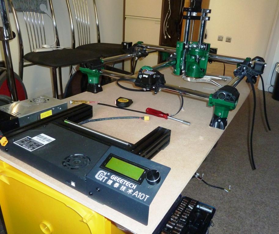
Have purchased most of the materials needed. Scrapping a Geeetech A10T for the motherboard and PSU. Using a new set of stepper motors, rather than from the A10T.
Printing the components in PLA on an Ender 3Pro. Have printed the four corners so far. Started the prints using a 0.4 mm nozzle, but the print times are excessive. Upgraded to a 0.6 mm nozzle which shaves a third off the print times. The Core will still take 28 hours, unless I refine the print parameters some more.
Update on the printing front. Have migrated to a 0.6mm nozzle and 0.4 mm layer height. Two trucks printed and built so far, with no problems.
Have a slight concern about the glass temperature of PLA. Like another contributor in the forum, I don’t have a garage, but a shed. Have had problems last summer with a PLA print for an R2D2 dome that warped in the shed when I accidentally left it in the shed in the heat. (Fortunately bent back to shape with hairdryer!) My question is - should the router head (c 2.5 Kg) be removed from the core in hot weather to prevent warping?
Most parts printed. Core currently printing, which will take two days with a pause overnight, which hopefully will work OK.
In the meantime have been working on software and firmware. The Crown has successfully been processed by Estlcan and loaded via Repetier and SD card onto the A10T. I’m using the A10T as an emulator for the MPCNC, before I strip it down to salvage the controller and PSU.
I had a few problems with VSCode randomly showing include errors, but reloading seems to clear them up. I had a copy of the Marlin on the A10T and was able to compare with the V1CNC_Ramps version. After a couple of attempts I now have successful V1CNC running on the A10 T. For anyone in the same situation here are the mods I made
Finished the 3D printing and assembled the rails, trucks and core onto a temporary board. Alignment has proved tricky as I’ve used too thin a set of rails, which have a some warping and circularity issues. Will finish the build and wire it up before considering new rails.
The belts are now attached and tensioned. Mechanically Ok to test and firmware Ok, just cabling to deal with. The serial connector stepper adapers have also been built. Spent a frustrating couple of hours trying to crimp JST connectors to make my own cables. Those things are the work of the devil! In the end I’ve given up and ordered some 2 metre stepper extension cables.
All wired up now. At first the X axis just sat there and stuttered. This was traced to a poor soldered joint on the veroboard serial adapter board. All axes move now. However, the vibration on the X and Y axes is excruciating. Part of that is down to using 25mm wardrobe rails - lesson learnt. I only used them as they were easy to cut, but, as it turns out, they are too thin. The other reason, probably the main reason, is that not all the bearings are touching the tubing. They can be moved round by finger. I’ve tightened everything up, except the one next to the stepper where you can’t get a socket into. This will involve stripping out the motor, adjust, put together until everything works x 4 trucks. I did the 45 degree slide test before assembly and it worked. Might I sugggest that the 45 degree slope test doesn’t work. You can get a slow slide down at 45 degrees even if some bearings are touching and some not.I think I will strip the machine down and get the adjustment done without the core. But that will have to wait until my bad back improves.
Made substantive progress today. Stripped the trucks down to get access to the adjustment nut in front of the motors. Whilst the trucks would slowly glide down the tubes at 45 degrees, some of the bearings weren’t touching . I found a better test was to push the perimeter of the bearings with a finger. After adjustment pushing the perimeter of the bearings moved the truck forward. Tighten just enough to achieve this with all visible bearings.
This done I reassembled the cross bars. Movement still noisy. Took the cross bars off and moved the trucks via the control panel. Only one motor was active!!! The same on both axes. Motors OK, so deduced the serial adapter board I designed must be the culprit. After a lot of bafflement I checked which wires on the stepper cables had coils on the end. The pins were different to the ones I had been led to believe on the internet. When I traced back, the adapter had one coil in one loop and 3 coils on another loop. This was sufficient to operate one motor and not the other. A rebuild of the adapters resulted in a very quiet operating machine. Ive run the Crown, without a pen, on the SD card and the core glides along effortlessly.
One final problem to sort. The LCD screen displays garbage after a few minutes operation, even though the machine moves properly. Time for another search of the Forum.
In Nth Yorkshire?
Was in in direct sunlight under glass? I can’t imagine the temp reaching anything like 60 or70C unless you have a pottery kiln in there!
You should be fine, there are few of us living in sub tropical or tropical areas and issues are rare!
My bug bear with where I live is the shed. Have a house in the country with great views, next to the village pub, but the downside is no garage, just a shed which is uninsulated. The brass monkeys get you in the winter and it’s like a sauna in summer. Whilst the glass temperature of PLA is 60 degrees C, it deforms at much lower temperatures. One of my earliest projects was a bowl of plastic roses on stems which sat on the dining room table. Over a short period of time, below 30 degrees C the 100% infill stems deformed from near vertical to horizontal. Obviously the MPCNC is more robust and braced by tubes, so I’ll go along with your suggestion, particularly as many makers live in hotter climates than me. The shed situation should resolve itself in a year or so when we move to be nearer the kids - hopefully to a house with a brick built garage.
The LCD screen was already wrapped in aluminium foil by Geeetech. It isn’t earthed to the controller frame though, which I will rectify.
This isn’t the first time I’ve had problems with emc and cnc machines. In 1980 I was tasked with converting a manual milling machine to cnc using an early Tandy home computer. The milling machine had been fitted with DC motors and optical read outs on the axes. Stepper motors were just a glint in someones eye in those days. We built motor control and reader interfaces and wrote the equivalent of Marlin in assembly code. It all worked well, except for the arcs from the motor brushes occasionally reseting the computer. We never solved the emc problem and the project was scrapped. Better luck, hopefully, this time round!
I am intrigued. My shed temperature is rarely below 30° in summer, once our temps get to 30 or so indoors we “cool” our house to 26, and I haven’t seen any sign of PLA deforming - I wonder if this is a specific issue with the kind of PLA. Out of curiosity what brand of filament are you using?
Various types of PLA, but principally I use eSun. I think part of the problem with the roses is that the stems, although 100% infill were only 5 mm or so diameter. Truly vertical there would be no problem. At a slight angle there would be torque applied to the stems by the rose heads, albeit only a few gram cms. Slowly, over time the stems bend. Similarly, with the pieces of my full size R2D2 dome the curved surfaces were only a couple of mm thick with the weight of the plastic straightening the curves when placed on a flat surface. Whilst the glass temperature of PLA is around 60 degrees C, it is not a sudden onset phenomenon, deformation under stress possible below that. In the case of the R2D2 plates a very small blast from a hair dryer on the lowest setting allowed me to recurve the plastic with hand force. There are articles out there about annealing PLA, but I don’t feel brave enough to try it. I could have used PETG, as in the load bearing parts of R2D2, but I find it difficult stuff to get right. I’ll stick with the PLA on my MPCNC and hope I can move to a house with a cool garage!
Whilst waiting for a palm router, due for birthday later in the month, I’ve been looking at CAD/CAM options for making the wasteboard. I’ve designed a board with an array of T nuts on paper. Looked at various programs to create the CAD and give me the CAM for the MPCNC. Fusion360 free version seems to be too restricted, another couple wouldn’t install properly, so I plumped for Freecad. Several hours of video tutorials later I have a CAD design for a board with an array of holes with pockets for the head of the T nuts. The CAM bit is proving a little trickier. I have managed to simulate milling out the T nut heads, but the through hole doesn’t get milled. I could use two models to create the two types of holes, but that doesn’t seem satisfactory. Will have to find some more tutorials to get to the final product.