I’ve spent a lot of time considering different options, from not getting a CNC to getting a Parf guide (do everything by hand but with some highly accurate templates), to full DIY, to Maslow variants, Lowrider to Longmill/Altmill (closed loop sounds nice!), to Shaper Origin (accuracy across long distances is hit or miss) and more. Last week, I decided to just go with the least expensive project with bounded time and cost and consistent capabilities.
There are many decisions I haven’t made, but here are a few:
PET-CF for all 3d printed parts, for low creep and high heat resistance; higher rigidity won’t hurt. I have PLA prints in the garage that have warped due to ambient heat; we have peak temperatures of ~115F and my garage is south-facing.
I initially did a long set of cauliflower calibrations (20+ prints across 2 filament types and 2 bed sheets, adjusting this script to do skew correction in slicer post processing because my Mk3S+ doesn’t natively support skew correction).
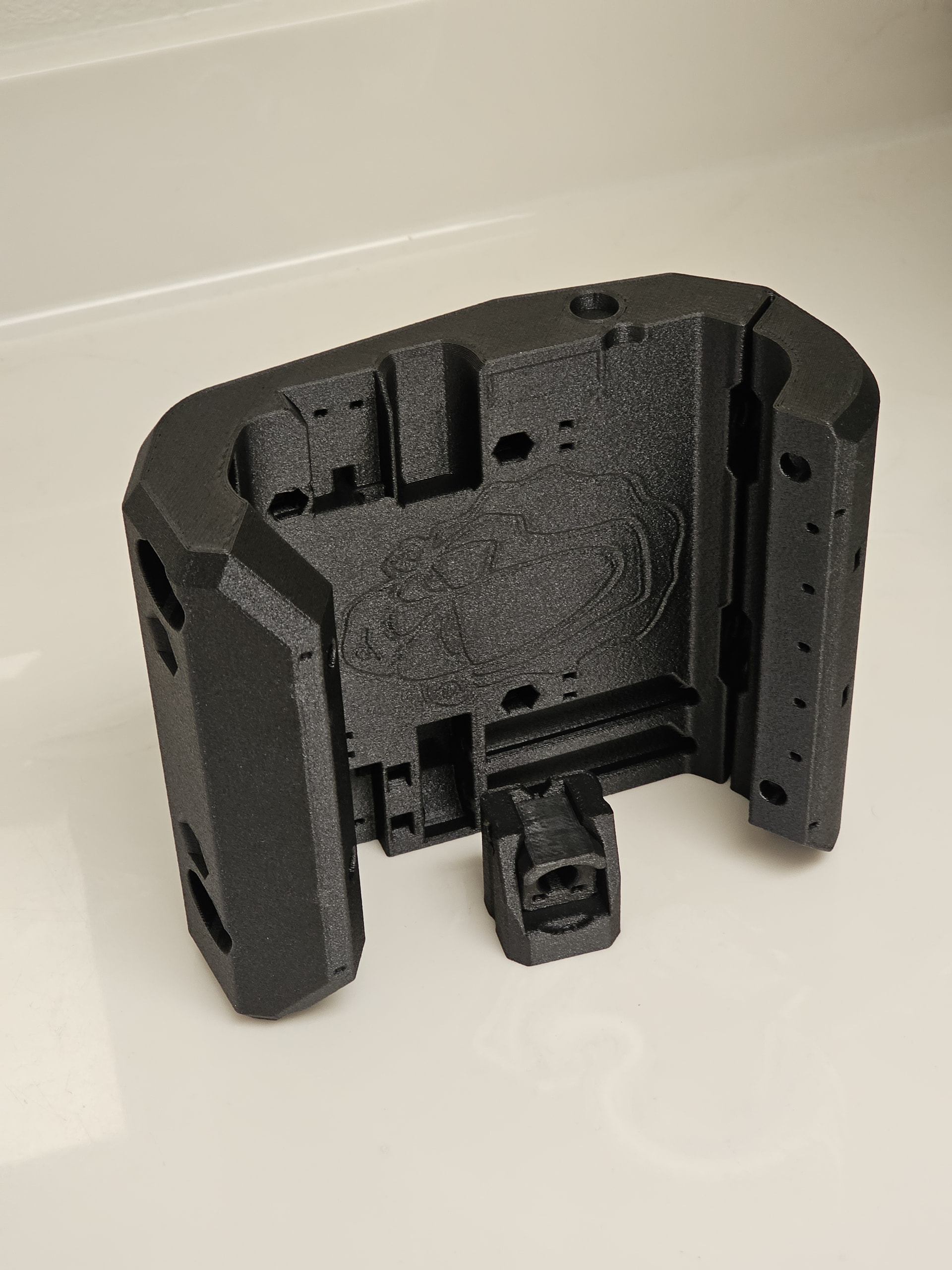
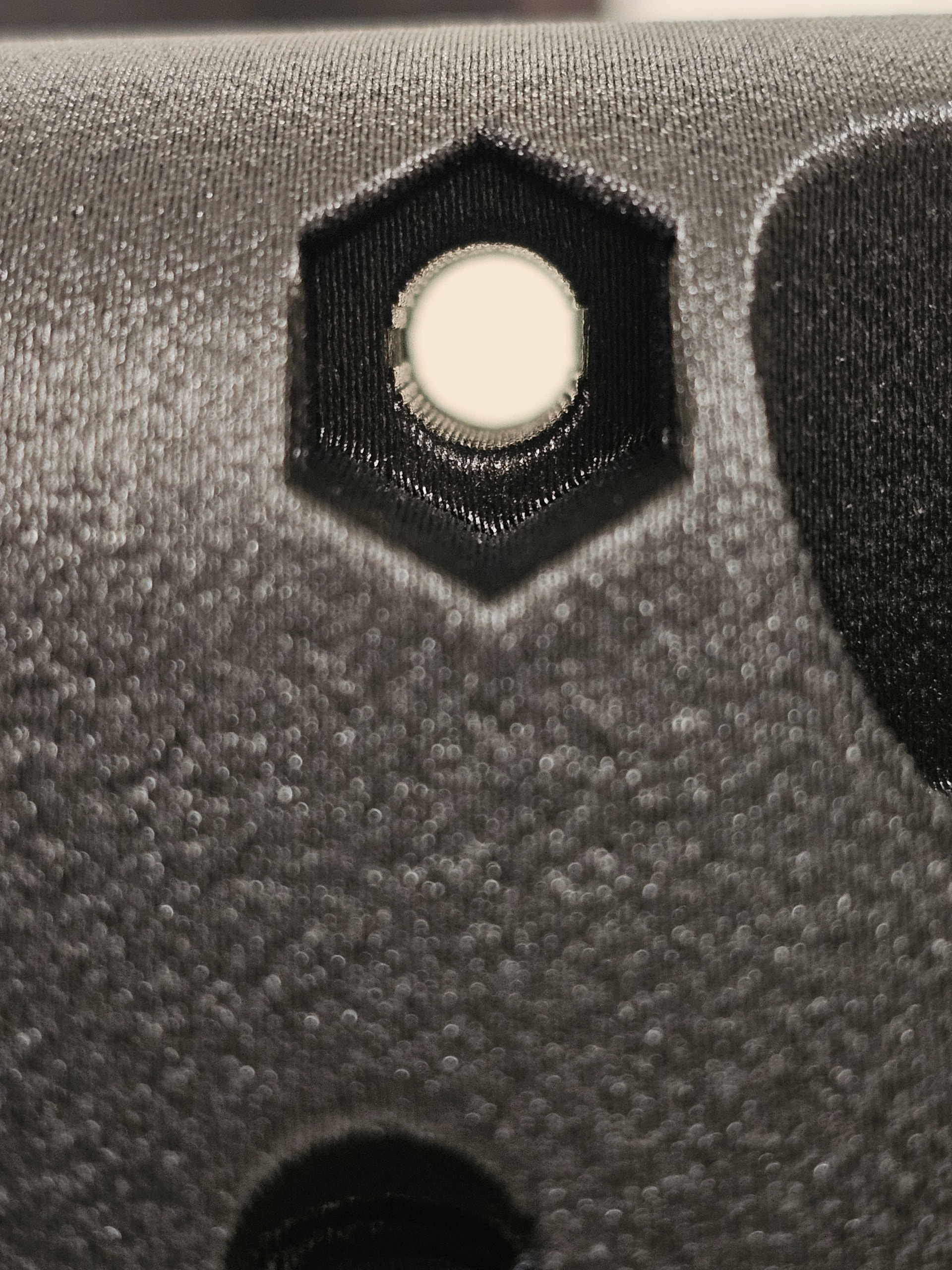
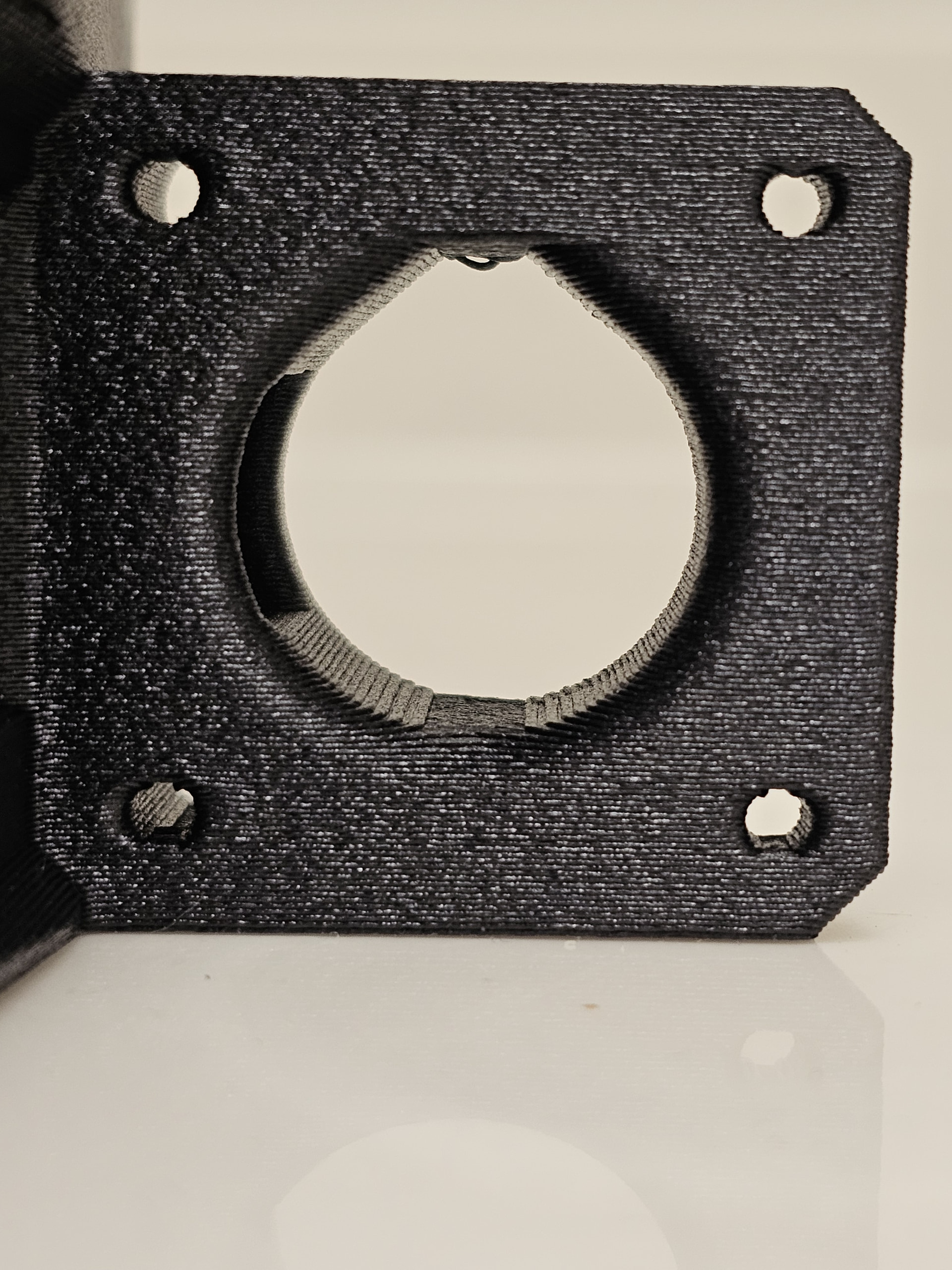
I’m currently printing using Siraya PET-CF on a Prusa MK3S+ with .6mm diamondback nozzle, based on this config. I’ve printed the z_stub_min and z_nut for a test, the fit was great, the core came out great, and I’ve got another ~5 days of printing to go.
I ordered a kit with Jackpot3, power supply, touch plate, 4x 1/8" bits and 2x extra endstop switches in case of issue. I considered the e-stop and drag knife, but they were out of stock.
I don’t have a wired trim router and eventually ordered an Autospin T1.
I still haven’t decided on machine dimensions or table.
At the biggest, I’ve considered getting a 5x10’ sheet of MDF, then using the lowrider to cut out ribs bracing the bottom plus a bottom sheet (yes, a torsion box requires a bottom; twist a taped cardboard box vs one with an open end) and hoisting it above the car in the garage. That would give a travel area of 49"x108".
I don’t think I’ll go that big, certainly not long-term. But it’s fun to think about limits. Most of the time a smaller machine would be better and more convenient; something able to easily work on 2x4’ or a little larger, so maybe 30"x60", which would require 42x72, a common dinner table size…
I printed the core with 15% infill, one extra perimeter, one extra top, and one extra bottom layer based on the default 0.6mm quality profile. The mass is about the same as a quality 0.4 mm nozzle profile with 30% infill.
I’m hoping to be cutting within 2 weeks, and I’ve realized I need to choose a table size soon.
My current inclination is to start with a single 5x10 MDF sheet on the garage floor, maybe on some 2x4 sticks for leveling, use it for a bit to get the workflow down and see what size table I will ultimately want. I got a quote a few months ago for a 5x10 sheet for around $100 delivered.
just getting my LR4 going. I settled on 60x100cm due to location issues. I’m already wishing for more!
The one thing I would suggest is to make your wiring harness up for the largest gantry size you might want then moving to a larger format is really quite simple, swap out the conduit, table and belts(or move the belt clips) and you’re off to the races.
Have realized anything I will be requiring accuracy & rigidity will be small stuff that could be machined in the corner of the envelope which should solve the rigidity problem. If I were starting today I’d build a 48" capable gantry on a short table and a table extension to run 4x8 material. The extension could be a bit flimsy as the large scale cuts would just be mostly 2d cutting out sheet goods. Any fine details could be setup on the primary accurate portion of the table. I would run the table extension on the end opposite the endstops so adding the extension would not mess up those and resultant squaring of the table.
I’m not sure exactly what you mean by a flimsy table extension and it reducing the accuracy? I don’t quite follow. Are you saying make a 2x4 cutting area, then butt up a 6x4 extension and swap EMT to have the full run? It seems that it would be better to have 2 independent surfaces?
This is what I’m currently thinking: build a 49 inch capable gantry, and have 2 “tables” that are sheets with EMT screwed on.
For one, install the EMT short ways on a ~37.5x60.5" (49x25" working area, still considering going out to 30"+?) board I can slide on and off my main 35x70" torsion box work table.
For the other, get a 5x10’ sheet for a 49x97-108" working area that can be put down on the floor.
The 4’ x ~2’ fixed table area would be faced perfectly flat and used for full 3d work that requires z axis accuracy. The 4’ x ~ 6’ extension used for 4x8 sheet work to do 2.5d profiling doesn’t really require super Z accuracy as you can just cut a bit deeper to make sure the profiles are thru the material but might be a mm+ into the spoil board in some areas due the table not being perfectly flat. If you need better Z accuracy a spoil board could be surfaced and it wouldn’t really be “temporary” at that point.