New 5 axis build in California

Started working on this August of last year, and it’s finally in a usable state. Been adding inserts into the waste board for work holding as well as holding the 4+5 axis.

For the most part, assembly was pretty straight forward. Everything is mounted to a 2’ x 2’ x .75" board of mdf, sitting precariously on a $10 ikea lack table(literally the most unstable table you can buy). I got as big nema17 steppers as I could find on aliexpress, powered by an skr v1.3 with tmc2130 drivers(more on this later). The spindle is likewise from aliexpress, a 500w space/sound efficient rotary tool compared to a router. Surprisingly, the torque is quite good especially as I found the newer versions run at 100V instead of whatever they were running at before. I also “modded” the belts to be 10mm instead of the standard 6mm. Getting the X/Y rails to work was as simple as doubling up on the bearings. Unfortunately, I got a pack of low quality bearings from aliexpress and they make some sort of rattling(?) sound when the gantry moves. Although the skr board can support individually wiring each stepper motor, the X/Y steppers are wired in series to save 2 stepper drivers for the 4th and 5th axis. Sensorless homing works great, the gantry slams right up against the side. The overall construction is as square as I could get it with just a tape measure. At 500mm x 500mm with a work volume of 365mm x 345mm x 180mm, a little out square can be worked out later…

5 axis adventures:
After seeing a relatively affordable 4+5 axis assembly on aliexpress(again), I decided I would try and get my mpcnc to support this. Luckily the z height ended up being high enough to mostly work with it. The construction of the assembly was pretty ok, steel everywhere, feels solid. One of the plates for the motor mount was bent on arrival tho, so I had to arbor press that back to flat. Overall, with its nema23 motors, I think it’s going to serve me well for a desktop cnc.

Now for the fun part, getting the software/firmware working. I didn’t just want 3+2 machining, I wanted full simultaneous 5 axis. You could probably get 3+2 working with some basic Marlin tweaks and a fusion 360 post processor, but I didn’t dig too deep into that. For full 5 axis control on the skr 1.3, it looked like smoothieware was going to be my firmware of choice. Unfortunately, it doesn’t support tmc2130 spi configuration natively. There was, however, a pull request with tmc spi support. Over the course of several weeks, testing this code as well as giving up and trying alternative firmware options, I finally figured out smoothieware doesn’t support software spi. Traditional hardware spi uses pins internally configured for the spi protocol, but skr decided that using Marlin’s software spi would be good enough. So I haphazardly copy pasted some software spi code that could bit bang the protocol and got smoothieware to communicate with my drivers.

Lastly, getting fusion 360 to output the correct gcode for smoothieware. Fusion comes with a grbl post processor, which is able to interface with smoothie quite nicely, as long as you’re in cnc mode. But grbl doesn’t natively support 5 axis control, so the post processor has those functions disabled. After some fiddling and copy pasting some post processing code for some haas machines, I was able to have fusion give proper gcode while being “machine aware”.

This project is far from over, but I think it’s got a good start going for it. I’ll eventually update with some 5 axis machining videos, if all goes well.

8 Likes

Definitely interested in seeing what you come up with for a 5 axis machine. Keep us posted!

Wow. Jealous of your 4th and 5th axis; respect for the work you put in for simultaneous 5 axis. I was hoping to one day do 3 + 2 with minimal firmware edits and/or postprocessing but you have really gone all in.

Do you have a project or something in mind that benefits from simultaneous 5 axis? I had a hard time thinking of a case where I would use it, which is why I was planning to quit at 3+2.

Welcome @dzhang97

Love the ambition. Looking forward to your build.

Any progress with this?

phew has it been a month already

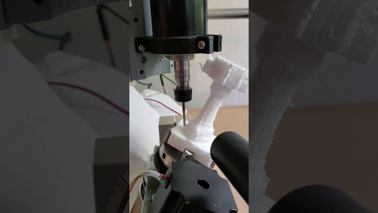
So far I’ve been able to get some 5th axis tests going, made a little test rook out of foam just to practice fusion 360. It’s not reeaaally simultaneous 5 axis, but I proved to myself I can go from fusion to part using all 5 axis. There’s a tricky bit with retraction heights, since the foam block was taller than could fit, so at some point I accidentally let the z axis pop out of the rails.

Besides that, I replaced the rotary axis stepper drivers. Instead of 2130’s I’m now running 5160’s, which can push 3amps to the drivers compared to about 1ish. The rotary axes needed this in particular due to how leverage works. I have 2 more 5160 drivers, since they came in a pack of 2. Maybe I’ll use them on the x and y axis, but probably not, since I don’t really forsee the force on the cartesian axis being an issue.

What’s really an issue is the rigidity of my machine. It appears during my original assembly, it managed to construct somewhat of a trapezoid instead of a square. This led to the gantry having quite a lot of deflection, which showed on some aluminum cuts. I have since torn everything down and attempted to resquare the frame and gantry. Everything seems to be moving significantly smoother, but I haven’t finished reassembling to really test.

Before I reassemble it in a mill configuration, I want to use it as a 3d printer to print a few parts. The stepper drivers have a tendency to get very hot, even overheat and lose steps if I turn up the current settings more. So I’m going to use an old 140mm computer fan and make a compatible case for the control board. That should keep everything nice and cool. Also, since I’m running sensorless homing, I want to print some endstops for the tube so as not to run the gantry into the ends to home. There’s also some bits and bobs like m4 nut adapters to make assembly and disassembly easier, etc.

More on the rotary axes, the belts and pulleys use the XL type profile. From googling, it looks like an imperial belt profile, which explains the 1/4 and 5/8 inch shafts. Unfortunately, there’s an awful amount of backlash on this profile, you can actually see the wiggle room the belt has on the pulley :face_vomiting:. And because the shafts are all imperial, its impossible to find the right pulleys for some low backlash profiles like htd or gt. I’ll probably end up machining my own pulleys to get this going, but for now I’m staying away from heavy cutting on the rotary axes.

A quality of life update on the spindle. I followed a smoothieware guide to setting up the spindle to be automatically controlled by the control board, and I designed and soldered some pcb’s that let me do just that. It can take anywhere from 10-30V and a pwm signal, and output a variable 10V output. It not really something mach boards need, but if anyone is running a marlin or smoothie based board, this is great. I made 4 extras and I’ll probably give em out once I verify they’re working properly.
image

To answer your question @jamiek, I built this ultimately to supplement my electric skateboard hobby, so originally the plan was to machine some herringbone gears. We’ll see how that goes, doesn’t seem like a lot of people do that :upside_down_face:. Also I’m a looong way from getting to that.

Still chugging along, thanks for the interest guys

1 Like

Just awesome. So many questions. I’m not even sure where to start.

Could 5 axis be run from an SKR 1.3? running nema 17’s of course.

I think you may have already said, but exactly what firmware are you running?

What 5 axis post processor are you using for fusion 360?

Great project.

great questions, lot of custom stuff to get my specific setup working, but yes, the skr 1.3 can run 5 axis. I’m using smoothieware as the firmware. Normally running 5 axis on smoothieware is not an issue, but I had to pull in some changes to add tmc 2130 and tmc 5160 support. But if you setup the drivers to run in standalone mode(or just use basic stepper drivers like the drv8825), everything just works, but you won’t have sensorless homing or the ability to get higher than 16 microsteps.

The rotary axes actually came with nema 23’s, which is how they can take the 3 amp current from the 5160’s. Based on what I was feeling, I’d recommend at least that level of power on the rotary axis, nema 17’s probably won’t do it.

As for post processor, I’m using a modified grbl post processor, where I copy-pasted some 5 axis related code from some haas and linuxcnc post processors. It’s a bit frankenstein as I couldn’t find much documentation on how to post process 5 axis, but it seems to work.

I am adding a rotary fixture to my lowrider which uses a mini rambo board. I would like to change that to a proper 4th axis so I can use the a axis to rotate a part and still retain xyz for milling. does anyone know if the mini rambo can do that? I’m guessing the answer is no. If no, what is a good board to to do that? I only have experience with Marlin so I don’t know if I change to the skr v1.3 if it will mess up the normal lowrider workflow.

Thanks for any guidance.

Dan

Marlin doesn’t support a 4th axis. You can swap the Y with a rotary axis, but actual 4 axis milling needs something like mach or linuxcnc.

Thanks Jeff. So If I want to upgrade my lowrider board to something that supports true 4th axis (not just remapping y to rotary) what board would you recommend?

I do not know. You’re going to have to dive down the rabbit hole. Maybe someone with LinixCNC can say for sure if that works? It isn’t for the feint if heart. Do you have a plan to create the CAM for 4 axis?

I thought I heard that Fusion 360 can do 4th axis even if it is not simultaneous.

I wanna say technically it should be possible in marlin with the 4th axis pretending to be an extruder? You’d have to do some post processing in fusion to make the gcode though.

nyc cnc just came out with a great video on 4 axis simultaneous in fusion

1 Like

Marlin messes with the extruder axis a bunch though. I bet you can get most of it turned off, by disabling linear advance, and allowing cold extrusion. You can also find the place where they look for ‘E’ and it is probably one line of code to change it to a ‘C’. I just worry the extrusion isn’t treated like a regular motion axis.

It’s been a while, lots of what feels like wasted time. I’ve been fighting with rigidity in my machine. The gantry is just not solid at all. I was under the impression the bearings holding the X and Y rails would all be in contact, but they aren’t on my machine unless i really torque down the tension bolts. Without the over torquing the bearings are just free to spin as they please and the gantry is able to wobble around on the rails. In an attempt to bring back some rigidity, I lowered the Z height to about 100mm, but I’m still forced to torque the tension bolts so much the rails are out of square. I guess I’m wondering if the bearings are supposed to be all in contact with minimal pressure?

That doesn’t sound right. Which parts did you print? And what size rails are you using?

‘C’ - Conduit or 3/4" EMT 24.5mm OD
’F’ - Foreign or 25mm OD
‘J’ - Jumbo or 1” tubing 25.4mm OD

If you have to really crank down to make contact, it sounds like you either have the wrong parts for your rails, mixed sizes for rails, or a printer needs to be calibrated.

hmm yeah, I think I have the right ones. I bought the C version parts from the v1engineering store (didn’t have a printer), and the EMT should be 3/4". Maybe the tolerance on the emt is not good? I wonder if there’s something I could put on the bearings to help, like some sort of ring or roller.

Its not incredibly loose per se, but it feels weird to have to tighten a bunch to get that last bearing to contact the rail.