Hi,
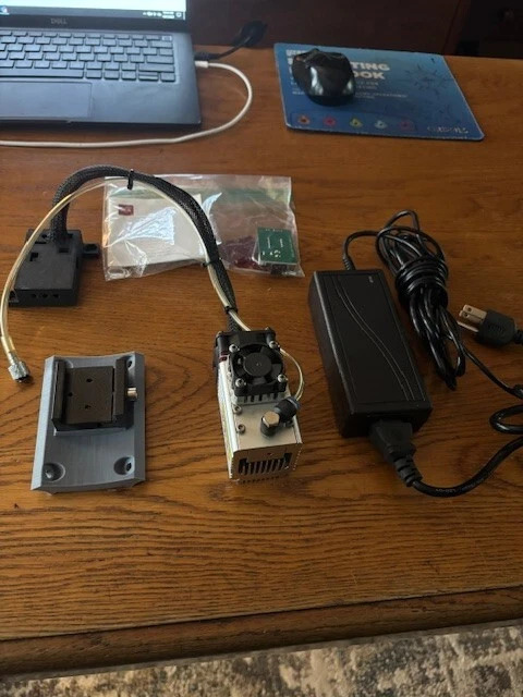
I need advice. I bought a used module from a guy on this forum but it didn’t come with any instructions or cables. I have no idea how can I connect it to the Jackpot control panel to make it work.
Can someone point out on a picture of the panel which pins do I need to connect my laser to?
I assume I will need to buy Micro JST MX 1.25 4Pins Connector too. What gauge wire should it be?
It’s OK to @ tag whoever sold it to you to continue asking for help.
You haven’t given us enought details about your machine. Since you’re posting in the LowRider section of the forums, I’ll assume you have a LowRider. What version? What power supply are you using (voltage, current ratings, source?).
Your pictures aren’t detailed enough to show what exactly you recieved, nor how those existing cables/boards are configured/pinned.
You should also let us know how you intend to create gcode and control your laser (e.g. are you going to use LightBurn?)
To connect the laser to the jackpot you’ll need to pick a GPIO (I suggest GPIO 27), and we’ll need to hook everything up correctly. Again- we need more details about your specific LowRider to tell you how to properly set this up.
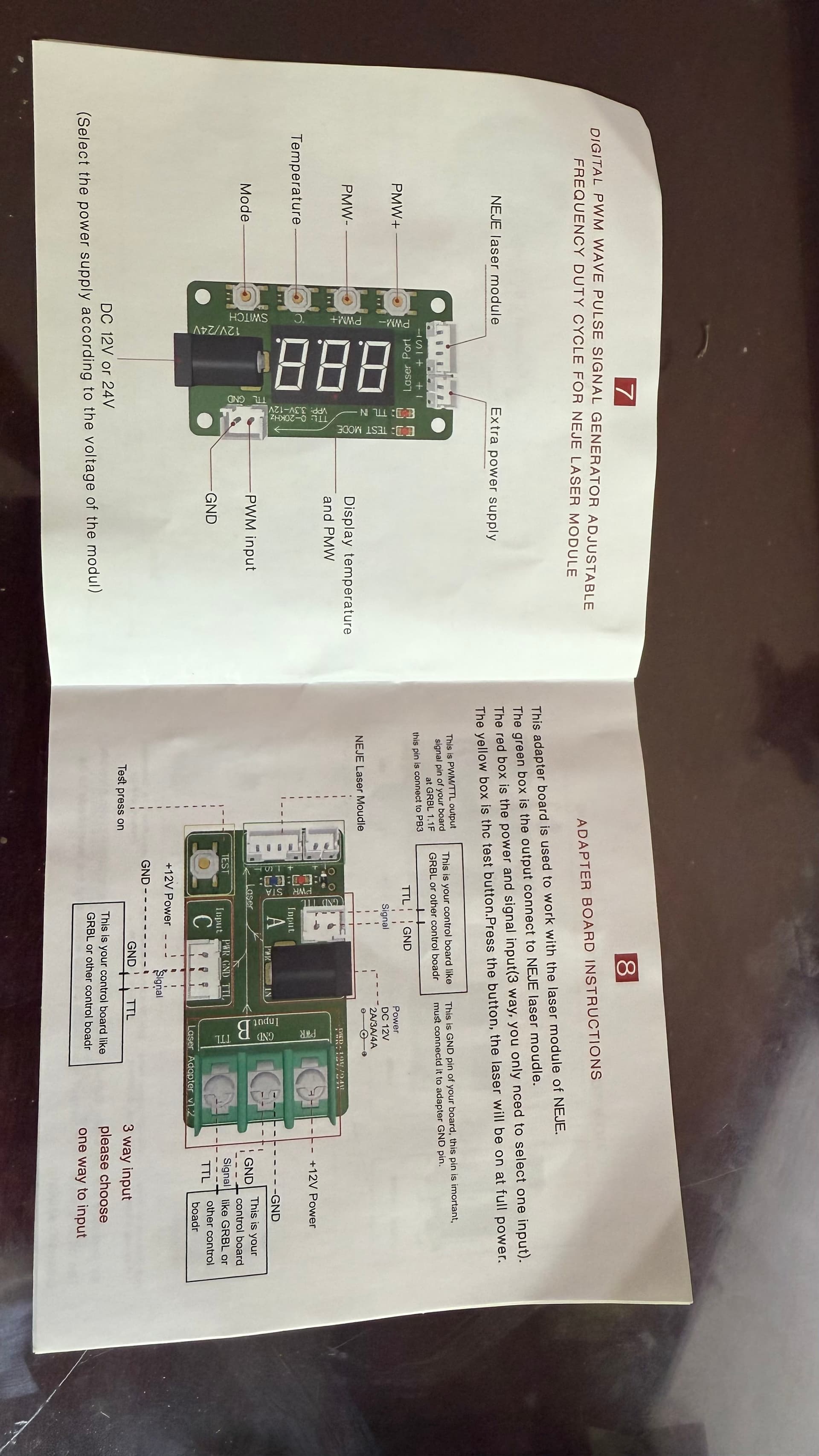
There are a couple of different ways to connect everything together. Most people use the companion board, which I believe is in the plastic bag in your picture. There will be a four-pin cable going from the laser module to the companion board. You plug the power supply into the barrel connector on the companion board, then there will be a two pin-connector from the companion board to your CNC control board. The two-pin connector attaches to the laser pin and ground on the CNC control board. We need to know what control board you are using in order to give you the laser pin number.
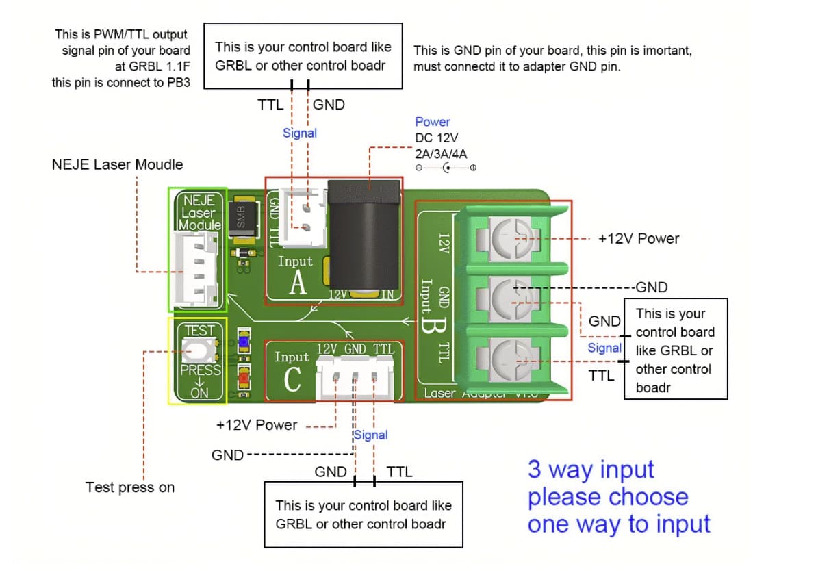
A search for “NEJE A40640 Manual” will yield multiple copies of the manual for this module. The main thing it provides is this breakdown of the companion board:
I’m assuming you have a Lowrider since that is where you posted your question. As for the actual routing, you have some decisions to make. The companion board can be mounted with the rest of your electronics, or it can be mounted with the core alongside your laser module. In one case you will have a long run with the four-pin wire. In the other case, you will have a long run with your power supply wires and control wires. In either case, I recommend using larger wires for the two power wires to avoid voltage drop.
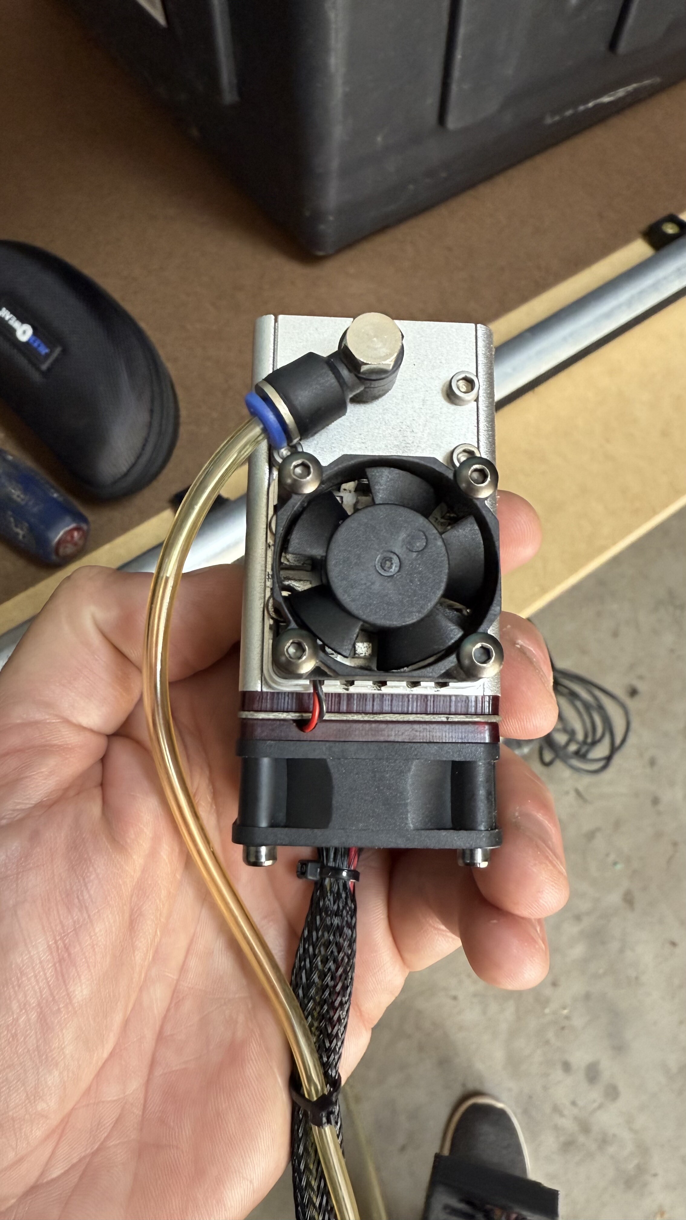
Your laser cutting will improve if you have air assist. Adding air keeps smoke off the lens, blows smoke away from the cutting beam, and puts out fires. The cheapest way to add air assist is an aquarium pump. I recommend larger tubing than the standard 1/4" for the long Lowrider run. You will lose too much pressure if you have a long run with 1/4" tubing.
It is possible to wire everything up without the companion board if you would prefer.
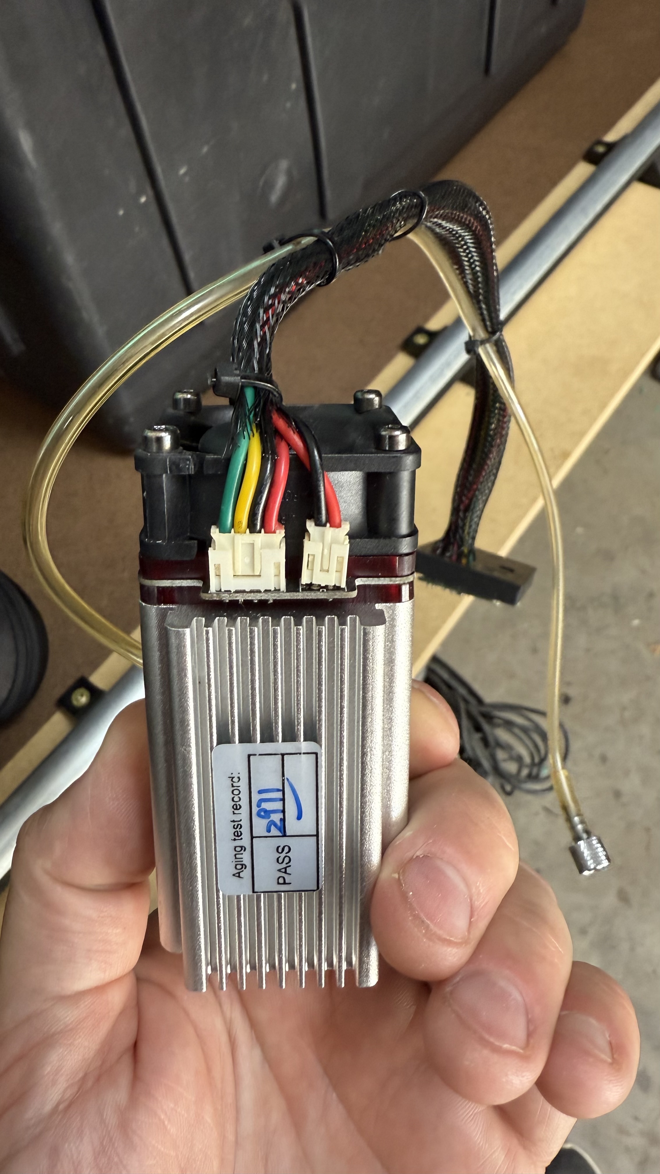
Note this is not a “40W” module. It is rated at 12W of optical power.
As for generating g-code for laser cutting, I highly recommend Lightburn. It is not free, but it also does not stop working if you don’t renew. You just don’t get upgrades.
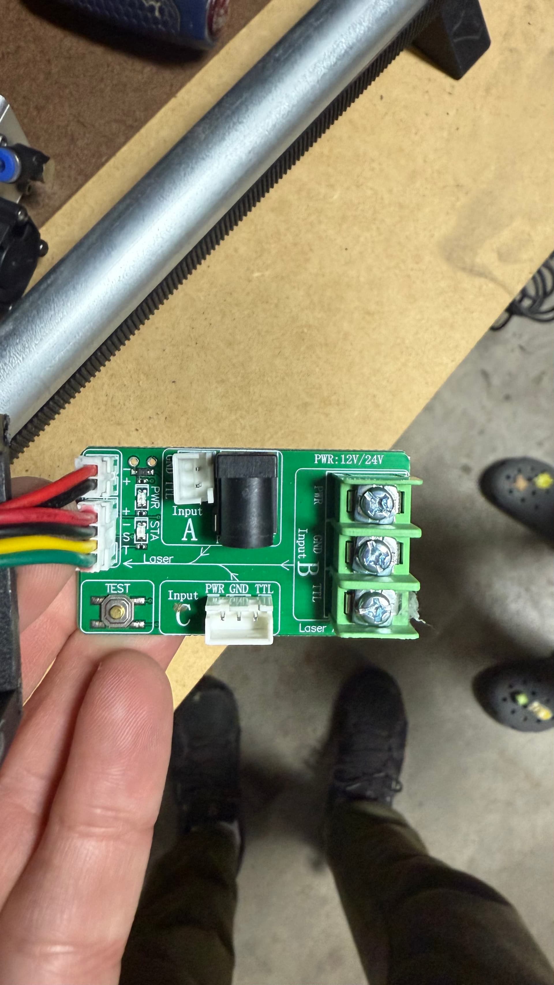
I have the earlier version of this laser module. Your version (“II”) is a bit different. Since it appears it has six wires going between the companion board and the laser module, it makes most sense to mount the companion board on the core and run power and PWM lines from the CNC control board.
Assuming the wires on the existing power supply are not long enough, I suggest cutting the power supply wires near the supply and replacing the wires with 18AWG wire long enough to do the job. You can connect the new wires to the screw lugs on the companion board labeled +12V and GND (my preference) or you can solder on the barrel jack harvested from the existing wiring.
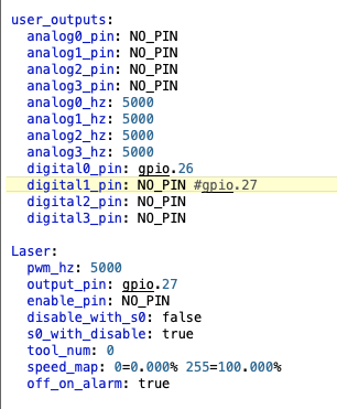
I don’t run the Jackpot, but I know there are a number of topics outlining the settings to use for a laser. The settings @MakerJim outlines in his post above look right from what I remember, which makes pin 27 the laser pin. This image by Ryan outlines an additional change:
On the companion board, use the two-pin socket labeled Input A to connect PWM and ground between the companion board and the CNC control board. These wires pull very little current, so larger gauge wire should not be required.
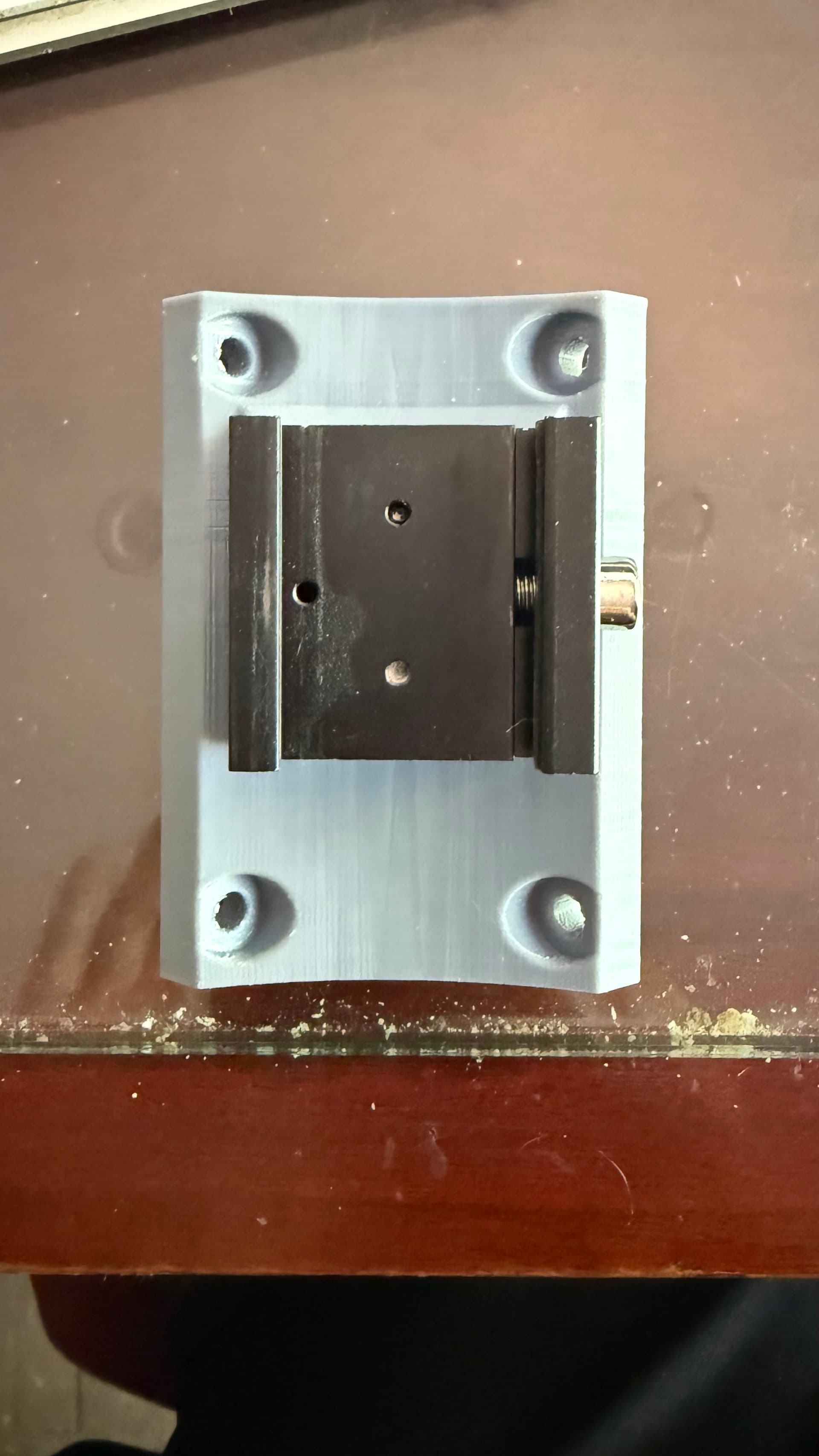
I don’t have a Lowrider, so I don’t know how to mount the laser module to the core. My searches of the froum are not turning up any topics outlining a laser mount for the LR4. There are topics for the LR3. If you don’t have a solution, you might want to open a new forum topic with this specific question.
Yes, good catch. You can only define a GPIO once in the config, so you have to pull GPIO 27 out of any other place it appears in the config.yaml.
I do have LR4s, but do not have a laser in them (I have a JL1/Jackpot and a NEJE dedicated diode laser machine)
Might be a good ping for @DougJoseph ask about the status of his LR4 kinematic mount. If you want to use the laser with the router (e.g. makers’ mark or laser engraving a work piece before cutting it out). Not sure if anyone is using one of these to put a larger laser module on an LR4 core.
Going by memory here. Regarding use for mounting laser — I think Dan was the one who tried using the older version of the kinematic mount, back from the days of Lowrider v3, with a laser. He had reported that it had too much flex. Thus I tried to make the newer version, that coincides with the release of Lowrider v4, to be beefier and more rigid. I cannot remember for certain, but I have a vague memory that somebody has used it for a laser.