Need tips/advice for how to -> laser enclosure w independent Z-up & Z-down buttons for cut bed

Hello, and good morning, fellow makers!

I’m in process of making a laser enclosure, and I have the wherewithall (parts in hand, for most of what is needed) to give it Z-up & Z-down buttons for raising and lowering a cut bed, independently of the control board. My big 100w CO2 laser has these kinds of buttons, and I find it tremendously convenient and a wonderful feature. The buttons don’t raise or lower the laser gantry, but rather the bed.

However, I need tips/advice for how to wire that to happen.

My rudimentary thoughts are: the stepper is DC, so I need a way to get DC power to it, whereas the incoming power is AC. Also, my general impression is that one of the two switches would complete a circuit on one of the wires (but which?) and the other of the two switches would complete a circuit on another one of the wires (but which?).

Finally, I have no idea how the existing Z system on my big C02 laser manages to keep the bed in position even while the power is turned off. What keeps it from falling down? Is it just friction because all the lead screws? Is there some kind of ratchet system?

I would surely appreciate any help and advice anyone can give. Thank you!

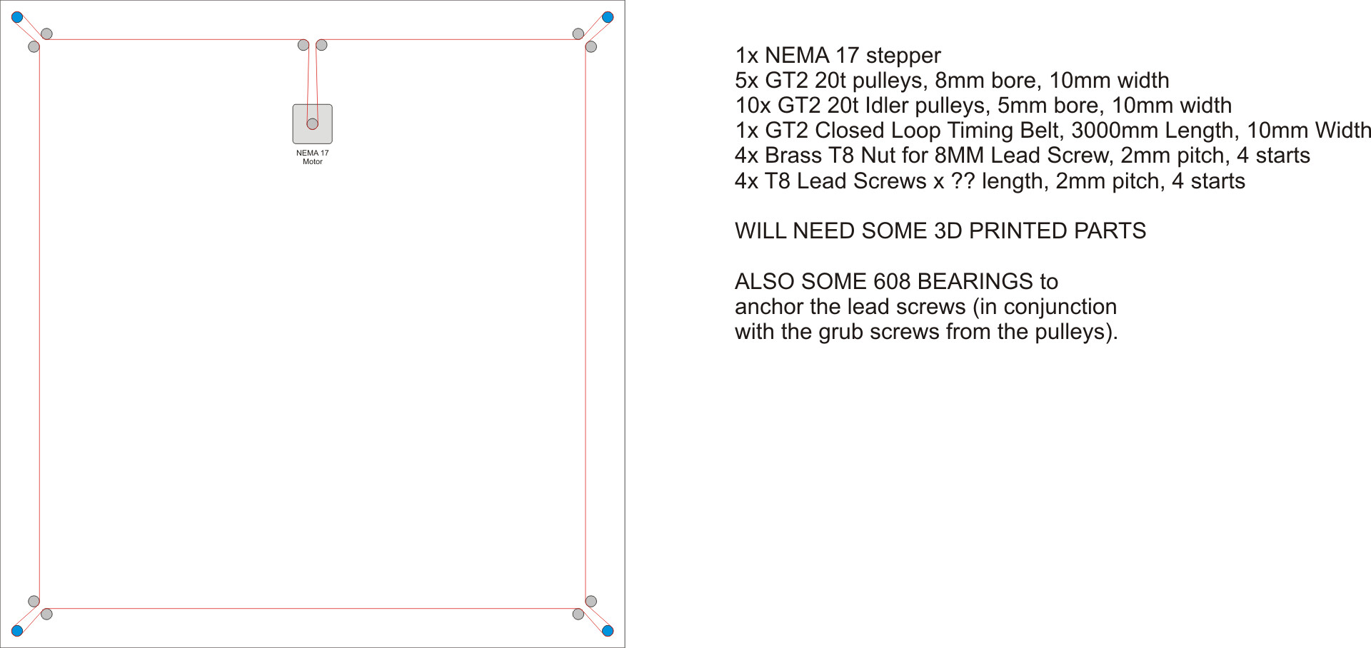
PS: in the diagram below, the blue dots represent lead screws (my plan is for T8 lead screws, 8mm diameter, 2mm pitch, 4 starts), and the red line represents a 3000 mm long GT2 belt, that is 10mm wide. The corner pulleys have teeth and grub screws, and the two “near” idlers for each are smooth. I welcome advice if this seems unworkable.

PPS: In case I get advice that a NEMA 17 is not big enough, I have a much bigger stepper I could use. I cannot remember if it is a NEMA 23 or even larger, but I think it is a NEMA 23.

Stepper Motors are driven by alternating coils, so you can’t drive them with DC directly.

So you will most likely want to get a stepper motor controller, as well as some way to implement the logic for swapping the polarity in the direction that you want to go. Here is a thread discussing the logic of driving a stepper using an arduino.

I think that it is relatively simple with the correct hardware. I’m sure someone will be along with much more details, or a better way to execute, as I am still a novice with implementing them, before I’ve used a Standard DC motor geared with a position sensor. Geared slow enough, it works, but cheap stepper motors and drivers have made that not worth the effort these days.

Hope this helps!

1 Like

Is it? If it is a NEMA17/23 etc then it requires a specific pulse train across its two coils for it to move…not DC. Off the top of my head, the easiest way of doing that would be something like this with an arduino.

There will be sufficient friction in that belt drive to hold the elevator without any power to the motor. Your diagram should work but you might want to add some form of sprung loaded tensioner in the belt to keep it taut.

SNAP!

1 Like

I agree with your drawing, and previous comments as I have run across this while diving down other avenues similar to your use case. So I know the concept is spot on.

https://www.amazon.com/Power-table-small-laser-machine/dp/B0094WLV7G/ref=asc_df_B0094WLV7G/?tag=hyprod-20&linkCode=df0&hvadid=644982501575&hvpos=&hvnetw=g&hvrand=14817081340266382144&hvpone=&hvptwo=&hvqmt=&hvdev=t&hvdvcmdl=&hvlocint=&hvlocphy=9013382&hvtargid=pla-1949307888606&psc=1&gclid=EAIaIQobChMIrvrL74T9_wIVcC6tBh0ZAw_iEAQYAiABEgJFt_D_BwE

The challenge for me (mentally) and what I never googled was where to find a continuous belt, or how I was going to join the two ends together (being I’ve only played with a “flat” belt, fixed in printed parts). Obviously a flat belt could be used if z travel is small, and the printed part traveling between the idlers, was the extend of travel from top to bottom of the lead screws. (Aka: how would a printed part even with TPU travel across the toothed gear). I made the assumption that a continuous belt, would dictate the distance between lead screws or the overall size of my z lift table. The other option I thought off, if belts were going to be a challenge, was the stepper motor with a small gear, driving a much larger gear in the center of the z table base. That larger gear would drive four small gears, one at the base of each lead screw. It would eliminate belt tension as a challenge, and or the continuous belt. However it would add other challenges (at least in my mind), like gear ratios, and I walked away, and side tabled the idea for now. Also would dictate more of a square shape, without adding more gears. But without sitting down and doing the math, I think if all five small gears were the same size, ratio shouldn’t be a factor, it would be down to force. So your drawing and other comments match (IMO) what is already available for purchase.

1 Like

My gridbot has a continuous loop of GT2 belt that drives two Z 4-start leadscrews. My bed is a lot lighter than your laser though, probably.

I agree with the other posters that DC can’t drive a stepper directly. I bet there are some dev boards out there that can drive a stepper with some buttons. If it were me, I would drink the koolaid and use an arduino and drv8825 driver. The awesome benefit is I could also add a screen for a DRO and have another button to adjust the jog speed. But those are features you didn’t ask for.

Maybe something like this?

https://www.amazon.com/2-Phase-Controller-Stepping-Adjustable-Regulator/dp/B09BTWQPTB

This isn’t an endorsement, I didn’t even read the description.

2 Likes

Thanks for the tips!

The drawing does not show the slots that are to allow moving the motor position to tension belt.

Thanks, all, for the awesome tips! It’s easy for me to forget about the need of a pulse generator/driver for stepping, especially when I’m drowsy! :blush:

One of the variations that @jeffeb3 linked, (see direct link below) is a dedicated controller for a single stepper, weighing it at under $12, and which has some nice feature options, including a knob for speed control. It seems to indicate it can output (drive power) for the stepper up to 800 mA, which I think would be sufficient for a NEMA 17. Does that sound like I’m on an OK track?

https://amzn.to/3r8OrN9

My bed probably won’t weigh a lot, and the items being lifted — the honeycomb laid on the bed, and the material being engraved or cut — also won’t be very heavy. On the honeycomb, I know it’s not heavy. On the material, that’s a strong “probably.”

1 Like

What laser are you using here? Our previous laser (an LPKF RF CO2, I think) used a motorized bed which was great, but I’ve found our current CO2 laser (locally re-branded Chinese DC CO2) with the movable lens setup to be just as easy/quick to set up, although a smaller working range. Great for cutting because that’s inherently limited. Maybe not for engraving.

The primary downside is that before we could move the Z height to be different for cutting and engraving without user intervention, which made for crisper engraving on stuff like thicker plywood or acrylic, but we’re mostly doing functional parts so I haven’t bothered. Could still do it manually, of course.

The much bigger issue with our laser is that the bed sags in the middle under the weight of material. not by a lot, maybe 2-3mm, but enough to cause noticeably worse cutting performance in the middle, which leads to the whole job needing to be run at a slower speed to compensate.

As for what’s keeping our bed up, it’s just the stepper motors that are geared down and used to drive the lead screws. No other mechanisms. I’m guessing the combination of correct number of starts on the lead screw and the gear ratio to the steppers would do it.

Edit:

Never mind, I think you answered my question while I was asking it!

1 Like

For $12, it is worth a try. It looks like it is targeting the smaller motors. If it is actually 800mA with a 12V supply, it should be fine. If it is the bleeding, temporary max, then it won’t be enough.

You can play games with ratios and the number of starts on your leadscrew. A 1 start needs 4x the rotations for the same linear movement, but it is 4x more force for the same torque. That is a simplification that ignores friction (which is significant). If you can get the nema17 to overcome the friction of a 1-start screw and you are ok with it going a little slow, then there is a high chance it will work.

2 Likes

@jeffeb3 Thanks for the helpful info! Good to know!!