All,
This is an initial concept drawing. As in my other threads, I prefer to think about things before I start.
I’ve had hobbies before where I didn’t. the joy of discovery is great when you are young. Now that I am becoming old, not so much. I enjoy less energy and smarter, wiser decisions.
I seek your wise counsel again. I’m running out of room in the garage, so need to store normal wood working tools above and below my MPCNC ideally. I was contemplating doubling up the legs and adding weight if I need to, but I this will be tucked into a corner, so I can put metal bracing direct to CMU wall with rubber vibration isolator for real structural stiffness.
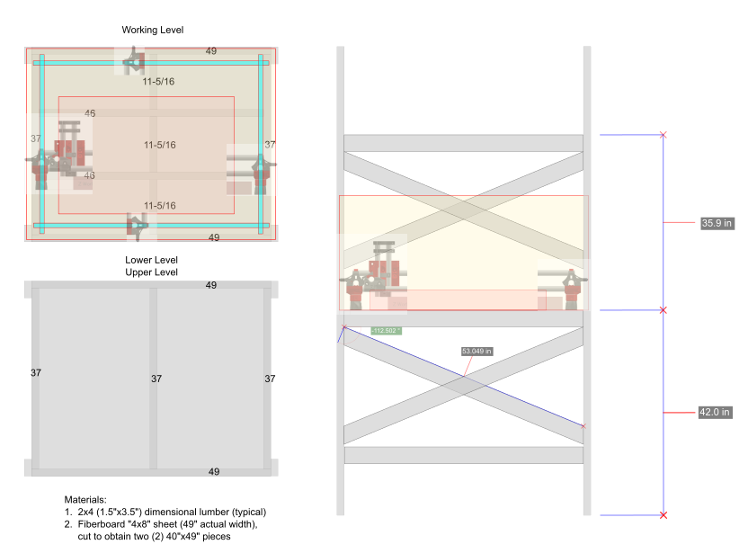
Please critique. work area is 25"x37". I scaled in the outer tubing rails, and ghosted in the parts to check clearances with the vertical legs.
I built an enclosure that has a bit in common with your design. Reflecting on what I got right and wrong and what you are attempting here.
I tossed my Burly on an old workbench. After a short period of time, the MDF of my Burly conformed to the hills and valleys of the old plywood benchtop. For my enclosure, to avoid the hill/valley problem, I took each board that supports plywood surface and flattened it. I don’t have a jointer, so I screwed angled aluminum to each 2x4 and ran it through the table saw to remove the crown of each board.
I decided to put more “joists” than the single one you use to support the plywood surface, but my enclosure is bigger than your rack design.
The most convenient place for me to store the vacuum for the dust shoe was under the MPCNC and to bring the vacuum hose up through the plywood. I did not plan for this and struggled some making it happen.
I did not consider wire runs nor where I wanted control board mounted when I designed my enclosure. I run headless, so this was an important detail I missed.
I cannot tell from your images, but the feet of the MPCNC look close to the edge of your rack. While you are not building an enclosure it is worth noting that on the Primo the steppers extend out from the rails and may prevent you from enclosing your MPCNC at some future date.
If you have taller 2x4 legs in front, you could use them to create a minimal “ceiling” above the machine to hang lights, vacuum hoses, and power cords.
@Zymurgist, interesting concept. Here are a few thoughts.
The 42” seems a bit high to comfortably reach the rear of the build volume. That may be an issue unless you’re a tall guy. I guess you could also use a step stool.
I second Robert’s comment about the trucks being close to the exterior. You may want to look at wiring options (e.g. tape measure trick) to see if you need to adjust.
You may want to build a torsion box to provide a more stable platform.
Have you accounted for a replaceable spoilboard? Can’t tell from the image.
Not sure what you are planning on cutting but you may want to double check if you have enough Z. Remember you will need to subtract the exposed cutter length + clearance from that working volume. Note that you can always increase the Z a bit and add an additional spoil board to reduce any stiffness loss from the taller legs.
I’m 6’3" so can reach the far side rail, and figured build volume will be easier, but thank you for pointing that out. I can also access the side from the left side, so long as the core is not dead in the back right corner I hope it will be ok. or stepstool.
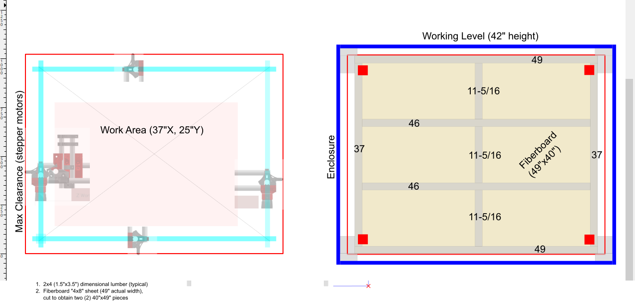
On the truck clearance (with steppers outside the rails), I did see how close that is in this mock up. unfortunately, I already cut the table fiberboard to fit it into the vehicle and bring home for this project… But I am thinking I could put short 2x4 spacers between the legs, and table surface framing, to cheat some extra width. That will give me some room to put rigid foamboard, maybe plus hardboard, around the four legs; to make a sound enclosure; and still clear the stepper motors, leaving some room for running wires… Will post revised drawing later, thanks.
z height, legs:
I would ideally like to carve soft woods, 1" to 3" thick. Everything I read here was to keep the Z height as small as possible to minimize deflection, so my legs were already cut evenly by the steel supplier, and are going to give a working volume z height of 4". I do have a lot of extra carbon steel tube and maybe can cut new legs with my angle grinder, and get a sanding disk for the disc part of my belt sander which will hopefully get them dead even. Getting the legs back out of the plastic parts may be an issue, however… What is your recommendation on a larger Z distance, if I add an MDF spoilboard on top of my working surface, and still want to carve on 2" thick wood?
for the working surface:
I had planned to do as the basic table build suggested; build the working surface with fiberboard, and then makes two cuts in it; going from the front to the back, inside of the feet; so it can be easily changed out later. Then use blue tape and superglue for holding down work pieces until I decide what direction I want to go for holding.
I googled torsion box video; unfortunately I don’t have a plane(planer?) or all the clamps sawhorses, etc. to build one. In my research people said not to worry about building a super flat surface; that I could use a bit on the CNC to flatten the spoil board surface out relative to the CNC rails. Is not such a bit that will fit the dewalt 660?
Thanks for the great input, kind internet stranger
Robert,
Thank you for your input. all good points, and well taken.
In my limited research, I was told not to be concerned with a flat surface, that I would use a surfacing bit to level the spoil board anyway. So currently was not that concerned about a super flat working surface.
I was planning to put two “joists” and also 3 ribs along the mid-span of each joist, to provide more stiffness and hopefully keep it flatter, but again was planning on relying on the surfacing bit for close tolerances. am i off on that?
Your point is well taken on the enclosure. I will modify this so get more clearance between that and the steppers, because I might add an enclosure (with removeable panels) right now.
I do have a ‘ceiling’ above the MPCNC which I can hang things; have been reading that for the wiring it is best to keep it in mesh, and keep it off the surface proper. I could hang it from above run it on a flat piece of wood with retractable lanyard to pull it back onto the tray, or attach on vertical “legs”. Then use the measuring tape trick for the z-wiring out to the core. Admittedly I haven’t noodled out how the wiring needs to be run, but I gather I want it to all run along the right side and back of the machine, so its out of the way… For the control I want to 3D print and build the handheld enclosure with the joystick, so I can operate it while peeking in through lexan. just hang that on the outside of the enclosure. control box - probably best if that goes underneath the work surface, i’m thinking.
based on both of your input, I also plan to change the design so that I can usncrew, and then slide out the entire work surface and its under-framing, so it comes out of the rest of the structure. This way I can add a torsion box if I decide I want it later. I can also switch this out for a “drop table” to be able to carve thicker items and keeping the z height and legs shorter, so it stays stiff.
I’d say try it out with your current legs since you already have them cut and see how it works for what you want to do. Like you’re saying, you can swap the legs out down the road. Mine were a bit tight during assembly but I was able to insert/remove them by sticking a flat blade screw driver between the slot (with screws removed) and rotating the blade while twisting the tube.
To quote Forrest Gump… “well I’m pretty tired now…” done thinking and drawing for the evening.
After the changes, looks like this. Drawn in inkspace. I started my first drawing learning on Versacad, but didn’t really learn to do any CAD until AutoCAD R13. That was a good release, solid like Windows 95. The late 90’s was good like that… People had to get software right before they made the CDs and shipped them out… Now I can’t play a single game on any system without starting it the day before I want to play so it can download a 576 GB update… Atari 2600 took seconds to boot up and that was 40 years ago. Some things we did better, some things we did worse.
Before I respond, my comments are really just a nit from someone who (over?)thinks about things. I’m sure there are many MPCNCs in the wild where the builder gave no thought to flatness and got satisfactory results.
Surfacing will mostly solve the flatness problem, though sometimes an additional tramming step is needed to keep the router perpendicular to the spoil board. But I would take care to keep your table/rack is flat as you can at the construction phase for the following reasons:
The more extreme the unevenness, the more material you have to remove during surfacing, and surfacing (without a vacuum attachment) creates clouds of toxic dust.
Surfacing does not completely address the issue of the feet of your machine not being all the same height due to unevenness.
The common wisdom is use your machine for a time before surfacing the spoil board. You may have adjustments that impact the surfacing for example. If you start out with a reasonably flat surface, then you will have significantly better results in some types of carving before you surface your spoil board.
I gather I want it to all run along the right side and back of the machine
Based on pictures, most people mount their control board towards the front of their machine and therefor run their wires across the front of the machine and down one of the sides (the side closest to the control board). This creates the shortest wire run to the control board. To move the wires to the back if the control board is at the front, the X1 wires will have to cross the Y of the machine twice, and you may have to extend the wiring to make that possible. With that said, I personally went to the extra effort of moving my wires to the back so that I would have an easier time with stock larger than my machine. It can stick out the front without worrying about cable chains. If you are not going to interact with a display on the control board, then you can just place the electronics on the back.
so I can operate it while peeking in through lexan
I think you would have a hard time aligning the bit up with the stock without being able to take a closer look than peeking through the window. I often have to look from both the front and the side to get my bit aligned the way I want.
I had planned to do as the basic table build suggested; build the working surface with fiberboard, and then makes two cuts in it; going from the front to the back, inside of the feet; so it can be easily changed out later.
The downside to this design (which is the design I see in most of the pictures of the machines) is that when you surface your spoil board, you will be creating a pit. It is somewhat harder to cut stock that extends beyond the cutting area when the cutting area is sitting below the edges of the board. When I upgraded to a Primo, I mounted my feet on a base board and mounted a spoil board (sized to just my cutting area) on the base board.
Good thoughts again, thank you. Since I’ve slept on this… am now thinking of building a torsion box Can cut it by screwing it to a carbon steel angle which I can buy for about $1/ft and running that against my table saw fence, so that at least one surface is nice and flat.
Would be great if that surface could drop down with manual adjustment. I am always frustrated when my laser doesn’t have enough depth, so can see that happening too without this feature.
I think I’ll mount the surface permanently to start, but build it in a way that i can go back later and make the height adjustable.
I ran mine across the back and then down one side to the front left corner where my control box is. The first version of the MPCNC I built, I had the X cables running across the front of the machine. This was a PITA as I was always scraping material over the cables, or would have to push the carriage all the way to the right of the machine to get larger boards to slide in between the front legs.
I would say you do want the controller on the front of the machine. It’s just easier to hookup cables and troubleshoot if it’s easier to get to, but I would agree with running the X axis wires across the back of the machine and then down the side.
I do this as well. My baseboard is a torsion box. Then I slide a 3/4" piece of MDF on the baseboard. Screw it down, and then surface that for my spoilboard.
Robert,
I am trying to figure out how to setup my table saw using this technique and I can’t figure it out.
What does the angle do, ride against the little measuring thing I just found out is called a rip fence?
Since you mentioned the word jointer I looked that up. A curious name because I would have called it a shaver.
Yes the aluminum rides along the rip fence. If you go to YouTube and search for “table saw jointer jig,” you will find a number of solutions. At their core they all do the same thing. They somehow attach the wood to cut to a second piece of wood or metal that has a known straight edge. Many use the manufacturer’s edge on a piece of plywood. That straight edge is run along the fence so that the cut on the opposite side of the board will have a parallel straight edge. Note for the use in my enclosure, I only needed used this technique on one edge, and I picked the crown edge of each board.
My quick and dirty method does leave screw holes in the wood.
Robert, what do you recommend for assembling the frame and surface?
-screw the frame together, and use wood glue or tough as nails adhesive caulk?
-screw the surface down and use wood glue maybe, so it is thin?
-should i put a bottom on the box? To make it like a “torsion box” that people make. I could use hard board Which would flex enough to get it seated against the uneven bottom parts of the 2x4s.
-also a video I watched the guy used saw horses to bubble level the framing before putting on the surface. Any reason I couldn’t just screw in the boards with the surface held vertically? It seems like the MDF will snug up to their flat faces.
I got the 2x4s leveled using the cut edge of plywood and found some MDF to to use as the base - seemed more durable than fiber board.
I don’t have great woodworking skills or tools…mostly construction grade tools to do construction jobs, so I’m not sure what the right choice would be with respect to the top of your table. I put in a number of flatteed “joists” to make sure my surface was well supported and would not dip. I just screwed my table top on (no glue). I made this choice so that I could disassemble the top if I wanted to make changes. Given the smaller size of most MPCNC machines compared to the LowRiders, I don’t think you need to go the torsion box route. Note that at some future date you will surface your spoil board. This surfacing will take care of any minor imperfections.