Howdy all… I’m a little slow and I can’t find how to wire in a microstepper between my Rambo Mini and my microstepper so I can add power to the NEMA 23 motor on my Z-axis.
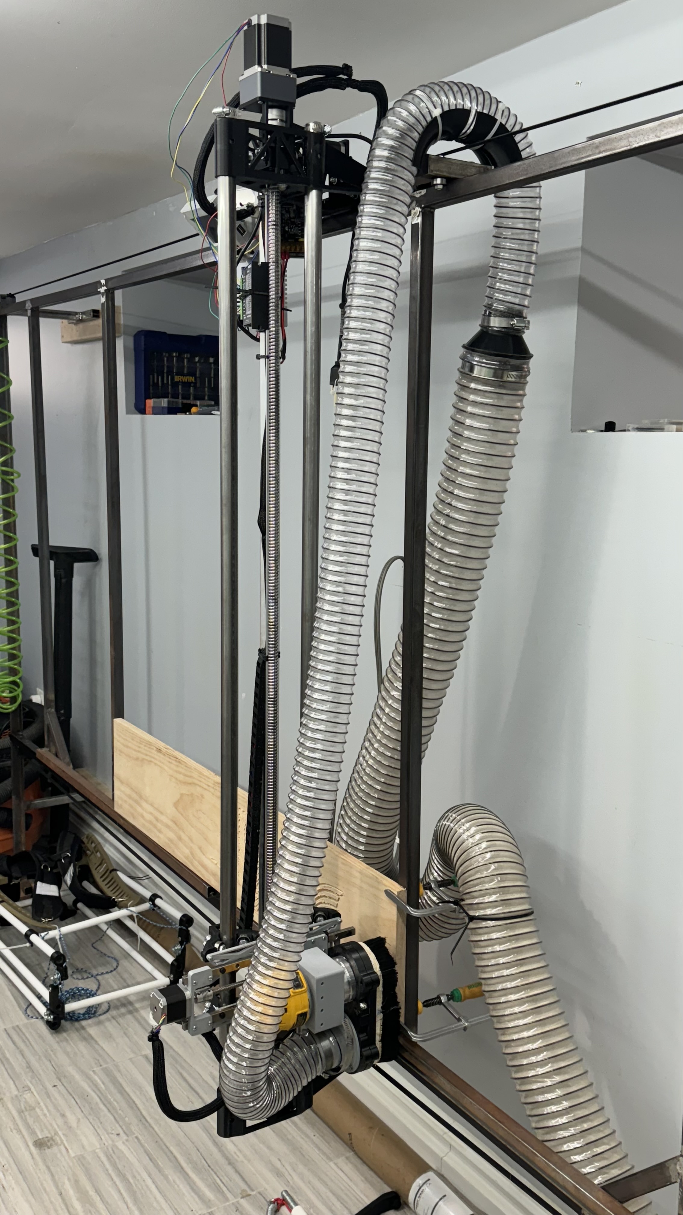
Due to a redesign, I had to make the z-axis stronger but it’s still skipping. The board alone wasn’t strong enough to turn the motor without burning out the board so I added in a microstepper so I could power the motor directly.
Unfortunately, I don’t know how to wire from the board to the microstepper so it tells the motor what to do. Right now it just makes noise. Any help would be appreciated. Thanks in advance.
You’re absolutely correct. Sorry about the vagueness. Here’s a couple thousand words that I’m not typing. Again. Thank you for your help in advance. Many things need cut!
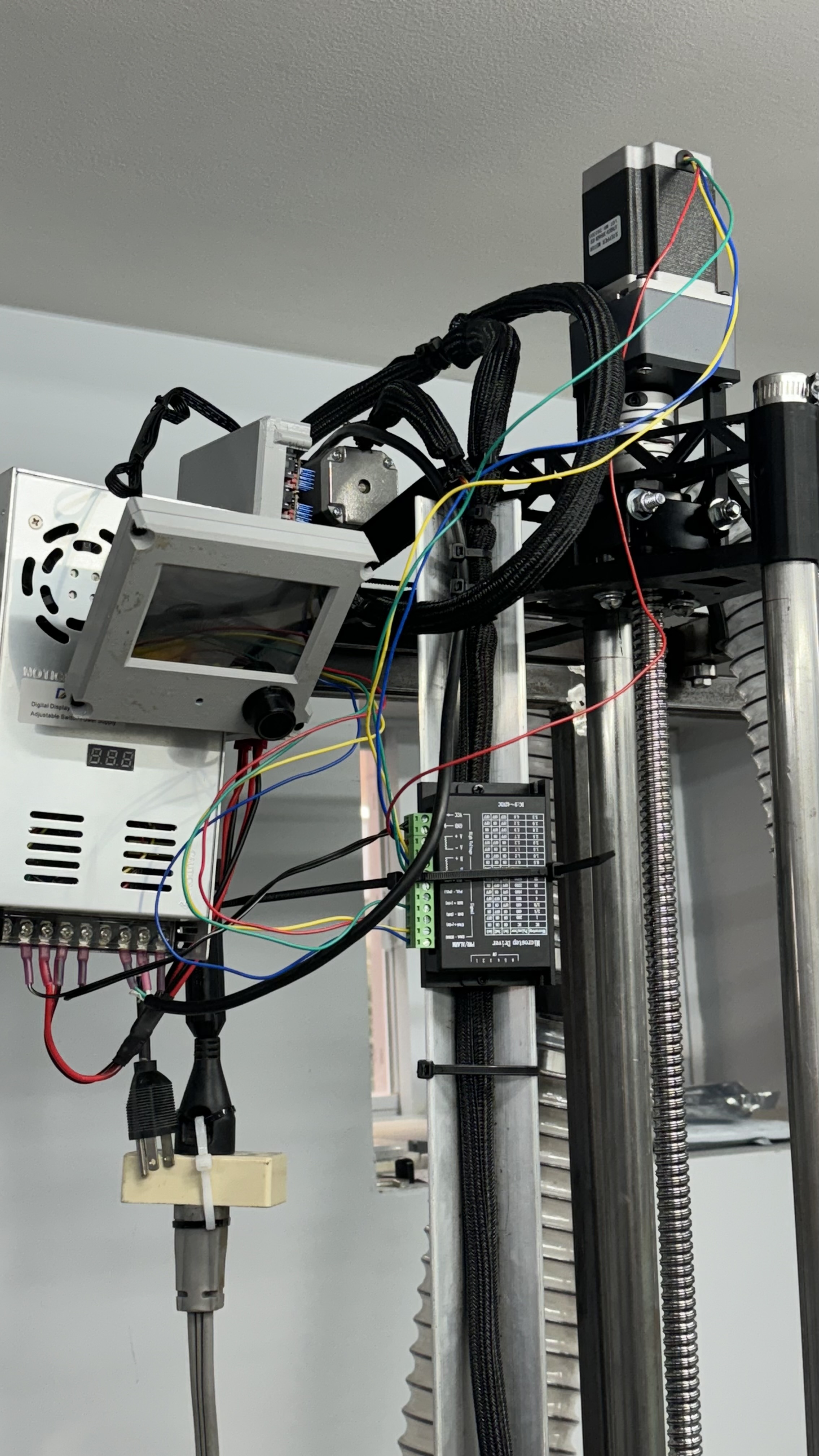
You’ve removed the stepper driver from the Rambo controller, right?
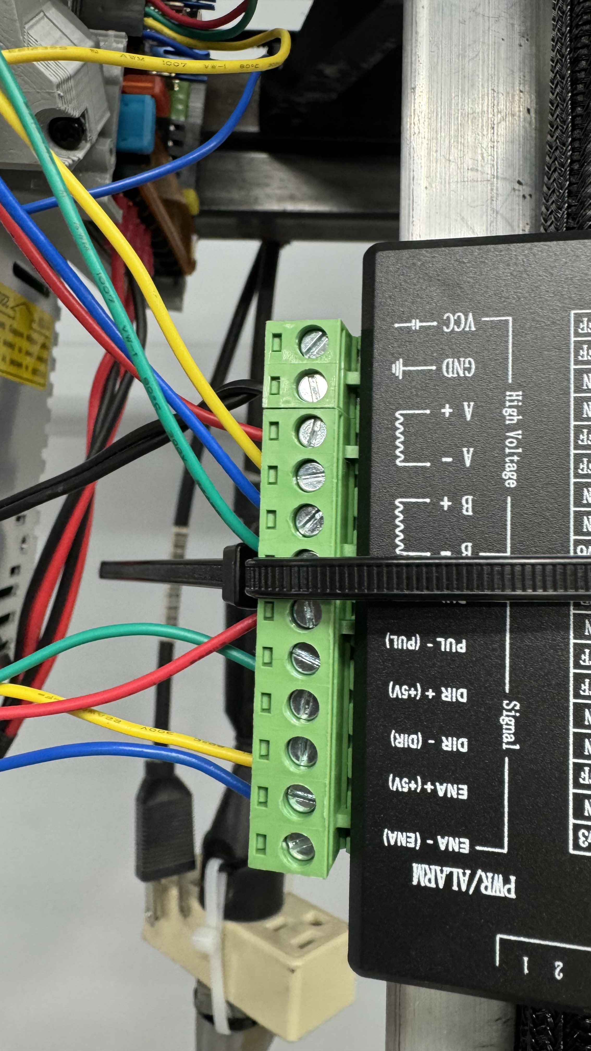
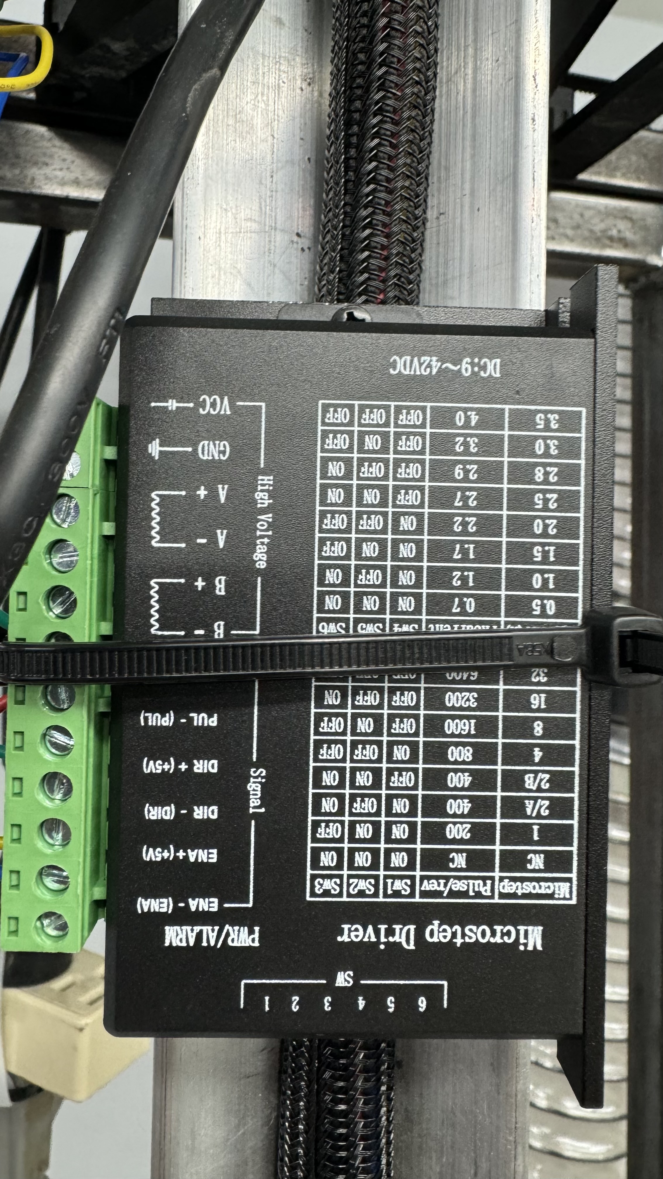
Most stepper boards I’ve seen use the Enable, Step, and Direction pins, so I’d connect Enable on the Rambo controller to Enable on the Microstepper, Direction on the Rambo controller to Dir+ on the Microstepper, and Step on the Rambo controller to Pul(se) on the Microstepper. Since Step/Pulse and Direction signals are relative to ground, I’d connect the ENA- and DIR- on the Microstepper to reference ground on the Rambo controller. Then the motor power supply goes to VCC+ and GND, and the stepper motor leads to the A± and B± connections.
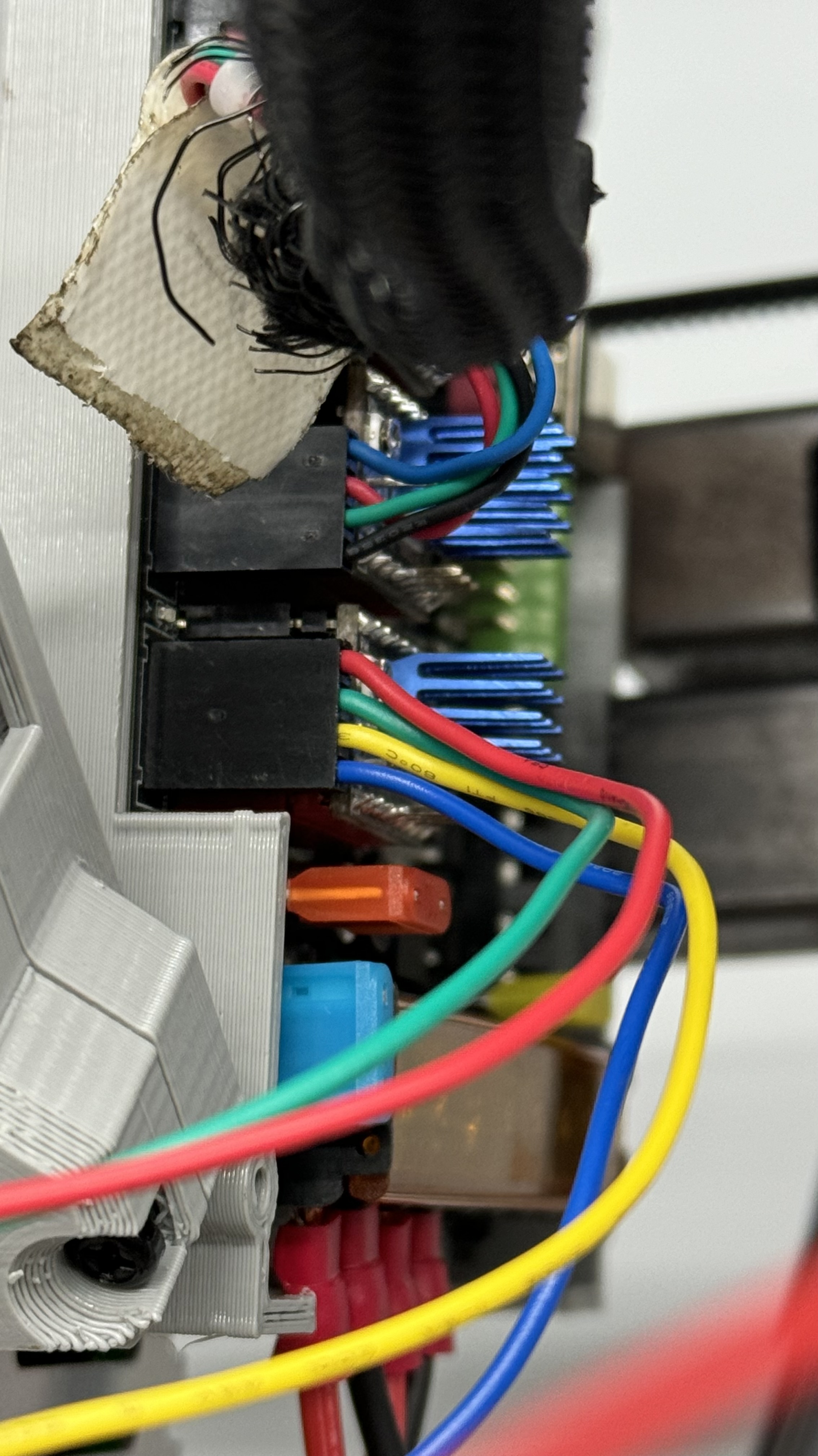
I can’t tell what the labelled connection is under the black zip tie in the image, but it appears to me you may just need the signal ground(s) added in to get everything going.
If the motors are buzzing, that may mean you’ve got the windings for the steppers intermixed. Each coil of the stepper should show a resistance when checked with a meter, or you can cross any pair of wires, and if that makes the motor hard to spin, that pair is a winding.
Thanks for your reply. Obviously I’m out of my depth. Do you mean I should pull the little board on my BTR SKR Pro 1.2 board? Is that the driver?
And then where am I finding be these Dir ± Pulse ± and Enable ± on the SKR board? I’ve looked at every schematic I could find and I don’t see those anywhere. I see them on my TB6600 driver and I have that connected up and the motor wired in (correctly this time! Thanks for the tip on the wire pairs) but no signal from the board to the new motor driver.
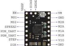
First things first. You’ve been saying “Rambo mini” but based on the little I can see of it, the photo looks like you’ve got an SKR Pro controller and TMC2209 drivers. That might help you find the right diagram to identify the pins you need.
The big black box is the new driver, replacing one of the little postage-stamp sized driver boards (with the blue heat sink) on the controller.
Quick search for the TMC2209 driver turned up this:
I don’t use either of those myself, so can’t provide any additional hands-on experience with them, but I think this should get you where you need to go.
AFTER COMPLETELY POWERING DOWN THE CONTROLLER (including the motor power supply and unplugging any USB cables) remove the TMC2209 driver for the Z axis. It has features your replacement probably doesn’t support, so just skip any pins that aren’t vref (controller voltage), en (enable), step, dir, and ground. Use wires to connect these pins on the controller to the matching pins on the replacement driver. This will get the control signals from the controller to your new driver. All the motor pins (VM, ground, M1A, M1B, M2A, M2B) will only connect to the new driver, although you’ll probably need to get the motor power and ground from the same power supply that’s connected to the controller.
Still having some issue with the frequency of the board for the x axis (it spins exactly 1/4 the speed it should) and changing the steps per mm only locks up the x-axis and makes the motor buzz. So 1 step forward into new problems.
Glad you’re making progress.
Too high steps/mm and too high acceleration can each cause lost steps. Try lowering the acceleration setting before increasing the steps/mm.
In your picture, you have a yellow wire in ENA+ and a blue wire in ENA- .
Where do those two wires come from on your driver socket?
If you are using a board set up for a TMC2209, the ENA signal is 3.3V and it is inverted- it goes to 0.0 V when enabled, and 3.3V when disabled.
That wiring is suspect to me.
Can you post.a picture of the wiring at your controller for the X axis that is giving you trouble?