I finally got myself a NEJE A40640 module and I am so happy. Haha. Thanks to this forum it was easy to pick which laser module to buy and here I am now, with a bunch of configuration and wiring to do!
My Ramps/Arduino (w. LCD and joystick) is currently on V1 513DL 2.0.9.2.
I wonder what features I need to activate in the firmware? I have found a lot of different deactivated laser stuff in the code.
There are laser options in the configuration adv file. You need to enable it and define a pin. The pin needs to be PWM compatible.
We don’t have laser stuff defined for ramps partially because it isn’t as well supported anymore and partially because this is one case where the 8bit processor isn’t fast enough for grayscale laser stuff.
You can definitely get it to work, and I encourage you to try it. But beware that you may outgrow it soon and want a jackpot or skr pro.
First, you will want to update to the latest version of the V1 maintained firmware which is 515DL. The laser features are enabled by V1 in this version, so all you will need to do is port your joystick settings, recompile, and flash your board.
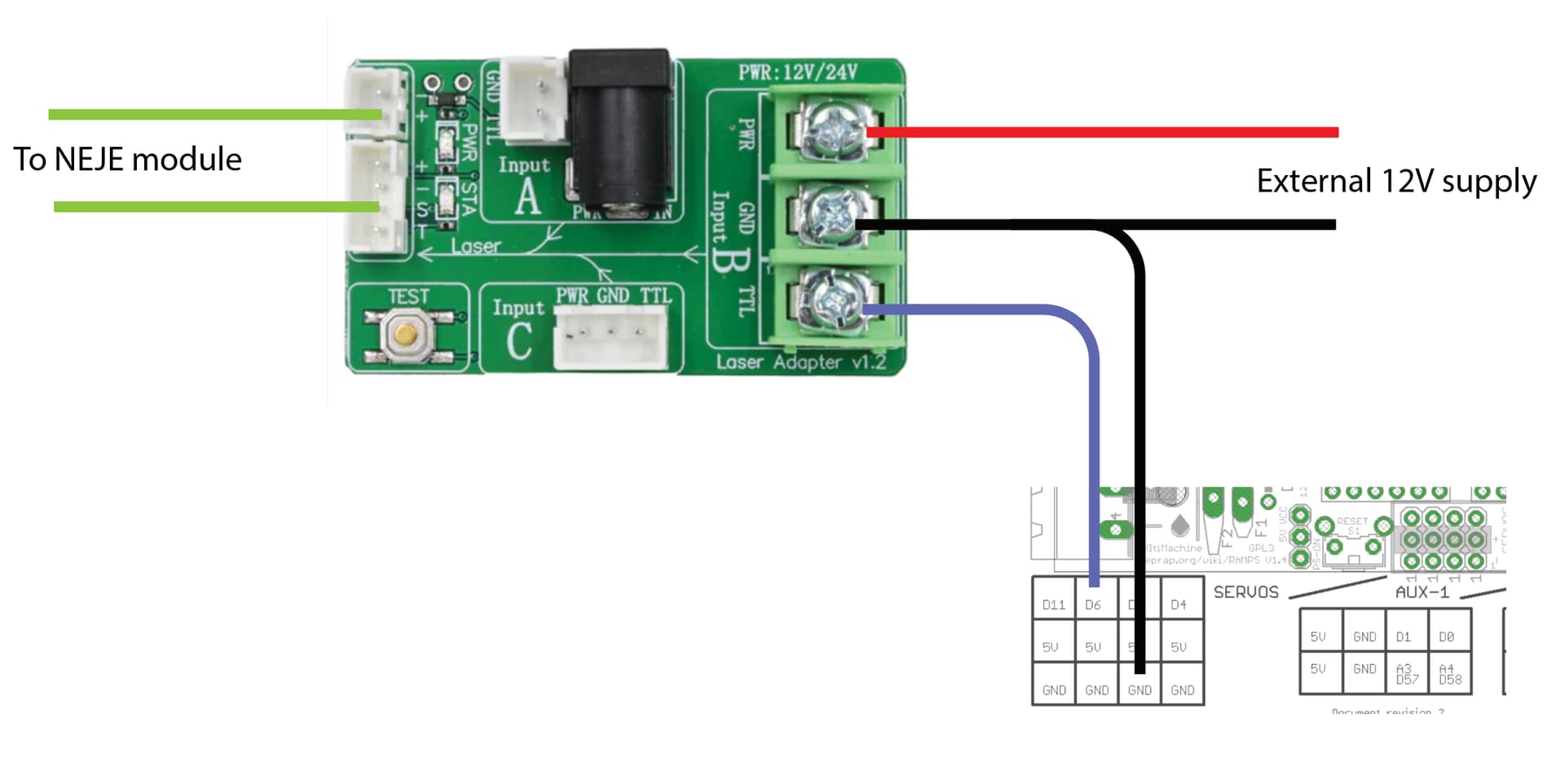
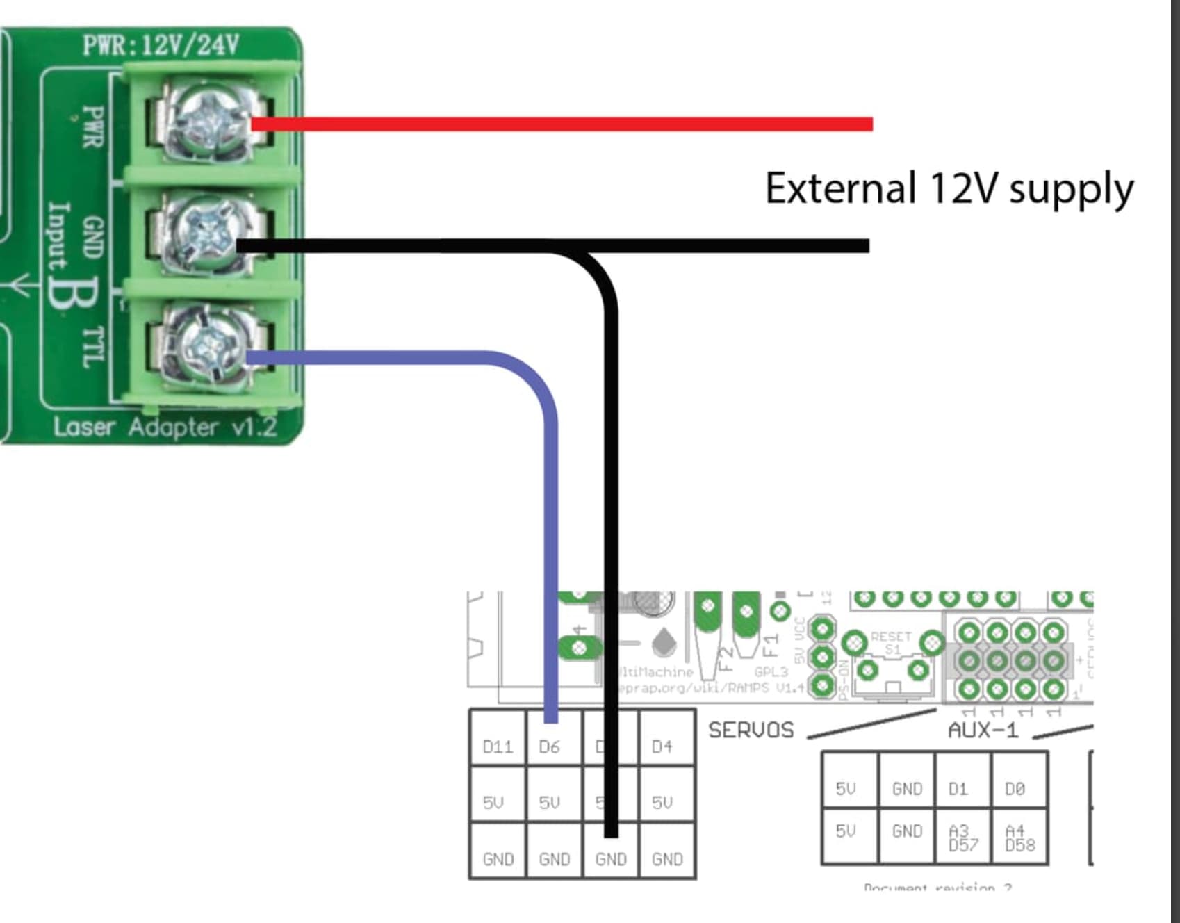
As for the PWM pin, I’m 95% certain it is pin D6 which is on the servos block. Look at any pinout diagram for the Ramps 1.4 board to find the pin.
In order to use the laser you will need the following placed at the top of the g-code file:
M3 I
This can be automatically inserted by your CAM software. I highly recommend paying for a copy of Lightburn for the CAM for your laser work.
I use a NEJE A40640 on my Rambo board. It has the same microprocessor as the RAMPS board. There are no issues with cutting. For engraving, you need to go slower than you could with the boards mentioned by Jeff, but it will still do the job.
There is a bug in the 515DL version of firmware that interfears with the laser turning on from the display menu. It has been fixed in later versions of Marlin, but V1 has not updated the firmware in some time. There are workarounds for the bug documented on other topics in this forum.
Aaah sweet, I finally managed to update to 515DL now. Had some troubles, but now it is running. Cool! There are laser options in the menu now, but as u said, the laser wont turn on due to the bug.
I have obtained Lightburn instead, and have added M3 I to “Start GCode” in Lightburn. The connection and running the Low Rider 2 with Lightburn works well, but the laser module is not activated.
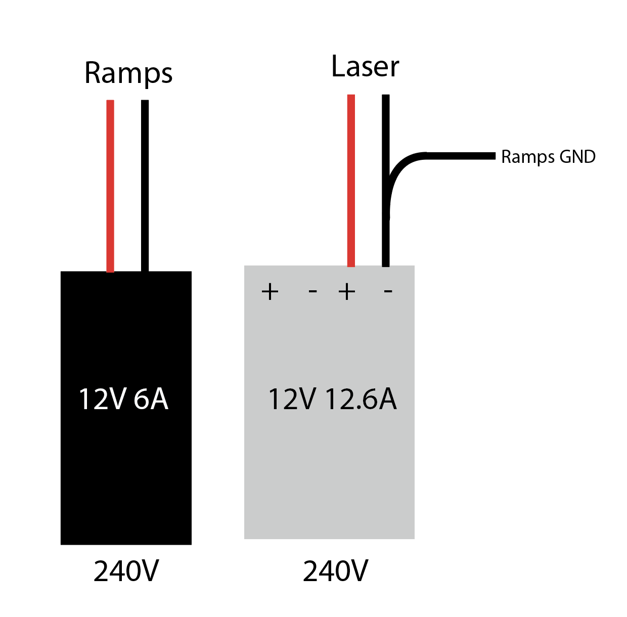
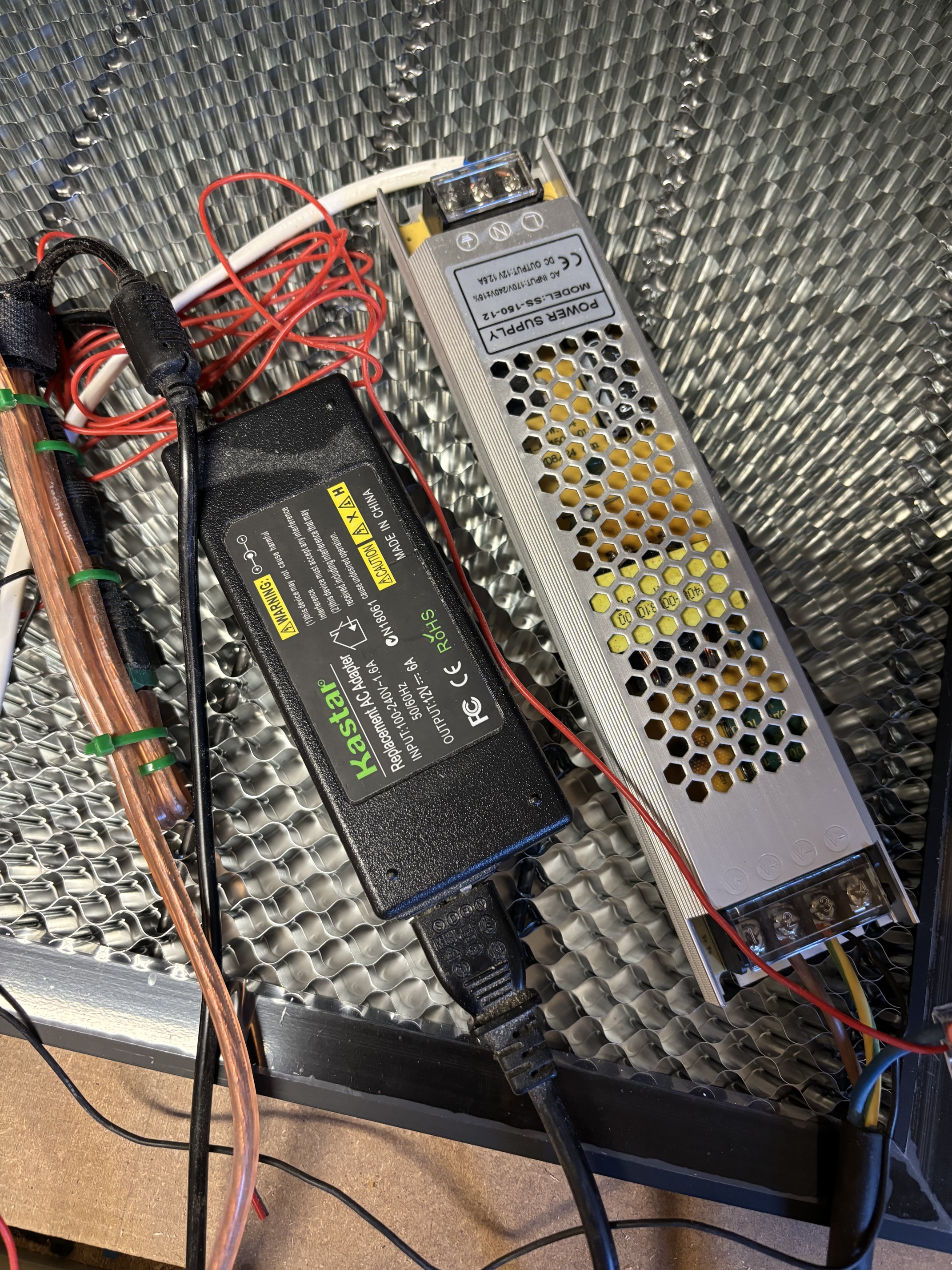
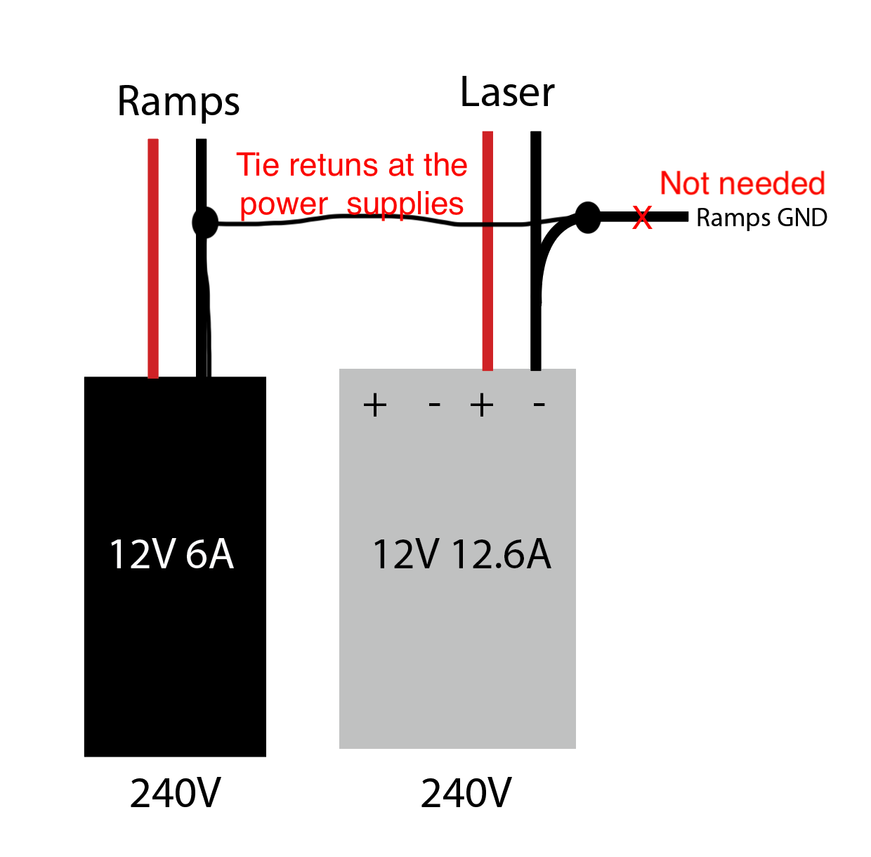
Last time I did this, I just ran a 12 AWG wire between the two PS. The wire had a ring terminal on one side and a fork terminal on the other side, but that was because of the terminals on the power supplies.
If there aren’t multiple return terminals on one power supply or the other, you can turn ring or fork terminals upside down (one up, one down), to fit more than one terminal onto the PS.
Or, you can make a harness that splices things, or use terminal blocks to splice things.