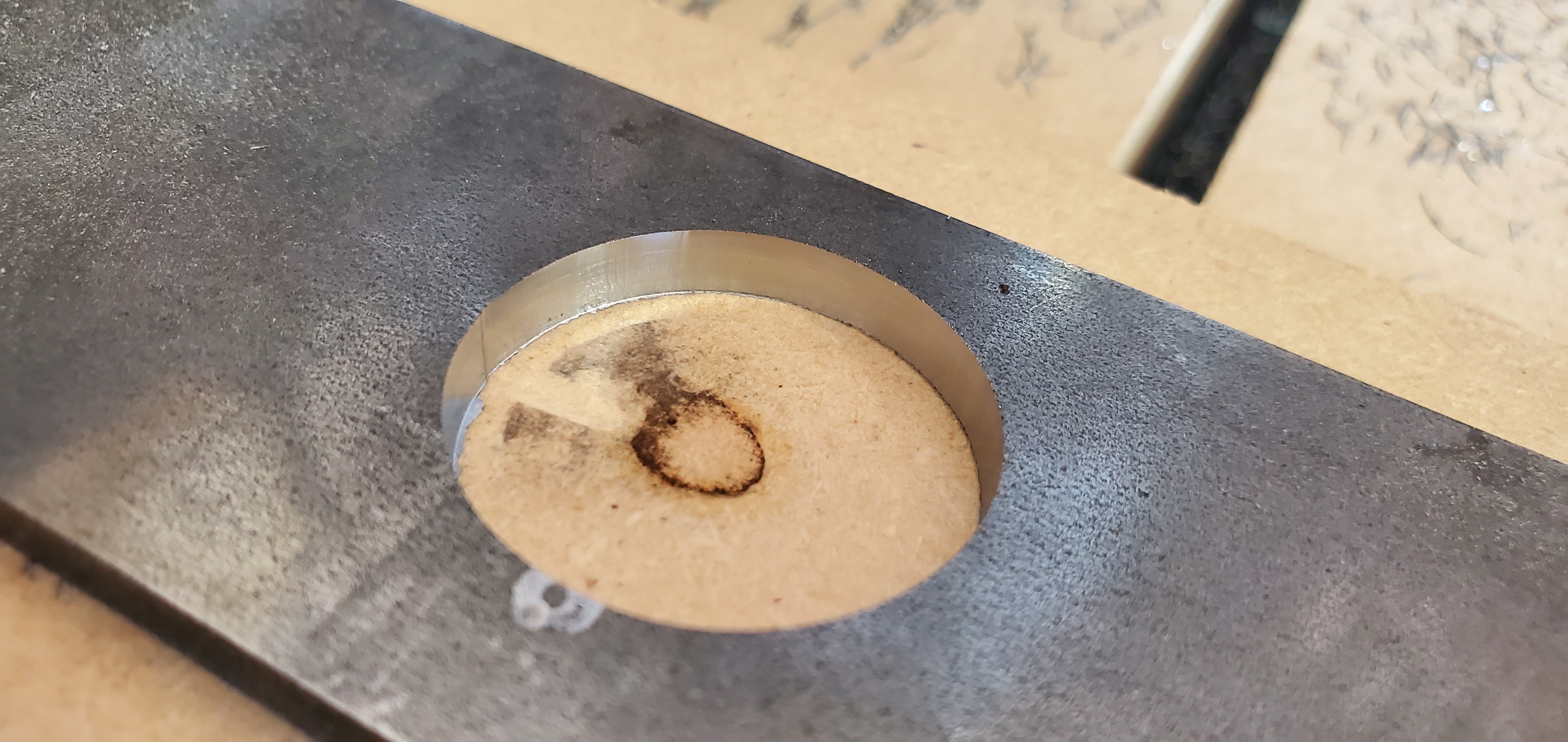
Bonus picture, finish pass on the steel.
6 Likes
Dude, STEEL!
1 Like
And not terribly slow, either. I think it was just a month ago I said “steel is beyond my reach, but I want to cut aluminum. I’m OK mocking up steel with wood then sending my files to the water jetter” or some such nonsense.
I’m not going to try any more slotting until I get those stubs, but I did do some tests at 0.010 doc. I think it was 35 or 40 ipm, but I forget already. Went well overall, but I think my mill might have gotten pushed up into the collet a bit. Didn’t cut all the way through, even though it was the stock setup.
3 Likes
WOW


3 Likes
I like how the chips are showing the magnetic flux of the bar stock. That’s pretty cool.
1 Like
Decided to push a little harder on the MDF. Fusion claims this was calculated to 144 ipm. I believe it on the straight cuts, but did we ever figure out why these things slow down so much in the corners?
2 Likes
Shoot that speed in the corners thing seems to be the old arc thing. Try the newest firmware and all of that should be smooth, or turn arc off in the CAM.
I wonder how fast you can push it. I love your build. My new one is not this small I don’t think but much closer. I can’t wait to push it and see how it does!
1 Like
I think my table would tip over at those speeds 
1 Like
I grabbed the new one right after you fixed it for the LCD turning off. I’ll take a crack at whatever is up there right now over the weekend.
As for how fast it can go, I need to get some workholding together! That’s 18k rpm at 0.004" cpt. I think the 611 goes up to something like 25k. That should give me a solid 200 ipm. That’s like 85mm/s. I’ve seen references up to 0.007cpt on a 1/8 mills. I’m pretty sure the 611 can handle that, but now we’re up to 350ipm (148mm/s). Seems like I’d run out of stepper before I run out of rigidity and power, but I gues there’s only one way to find out. I’ve got a little 1/2 inch MDF I need to cut some plates out of. Maybe a little scrap, too. I might try working up some full depth cuts on that, just for fun. MDF is really not fair anyway, because it’s so soft.
As for the size, I’m thinking about making it a couple inches bigger in each direction. I really don’t think I’m going to lose anything significant in terms of rigidity. Those tubes are TOUGH. Not a huge priority, though, and I’ve got other projects that need tending.
Any idea where I should start looking for that z vibration? Seems like I should take the whole thing apart and make sure the screws are in it real tight from the tool holder.
Oh yeah, I tried to load up a 1 inch piece of mahagony to cut a jewelry box, and I couldn’t get enough tool over it without pushing the z over the bottom bearings. I think 3/4 inch is max if I want a through cut. Which is fine, because I really wanted to push on 1/4 inch aluminum.
Just relaying this for the stats, because eventually somebody will ask.
1 Like
Cut some keychains for a friend. She saw some of the plastic “Covid Keychains” people use to avoid touching certain types of handles and wanted something similar for gag gifts. I have serious doubts these things are useful to anyone, so I put a cap lifter in them to solve that problem ![]() The 3D printed ones work surprisingly well. But you know, I have this thing that cuts aluminum…
The 3D printed ones work surprisingly well. But you know, I have this thing that cuts aluminum…
Sorry for the corny music, but the wife came out and we were having a conversation in the background that doesn’t need to be on the internet.
Oh yeah, and I saw that a couple of my outer tube rollers (where are we with names for these things again?) are kinda loose. Might have more to do with that chatter than the Z.

9 Likes
Well, the firmware I had was the same one, but I got a fresh copy anyway. 425D I think it was, published April 4. Just a reminder, I’m on the archim 1.0.
As a side note, every time I try to flash the board in the arduino IDE, it tells me the flash page is locked and I have to hold the erase and reset buttons. Also, when uploading, the led doesn’t flash like the rambo does.
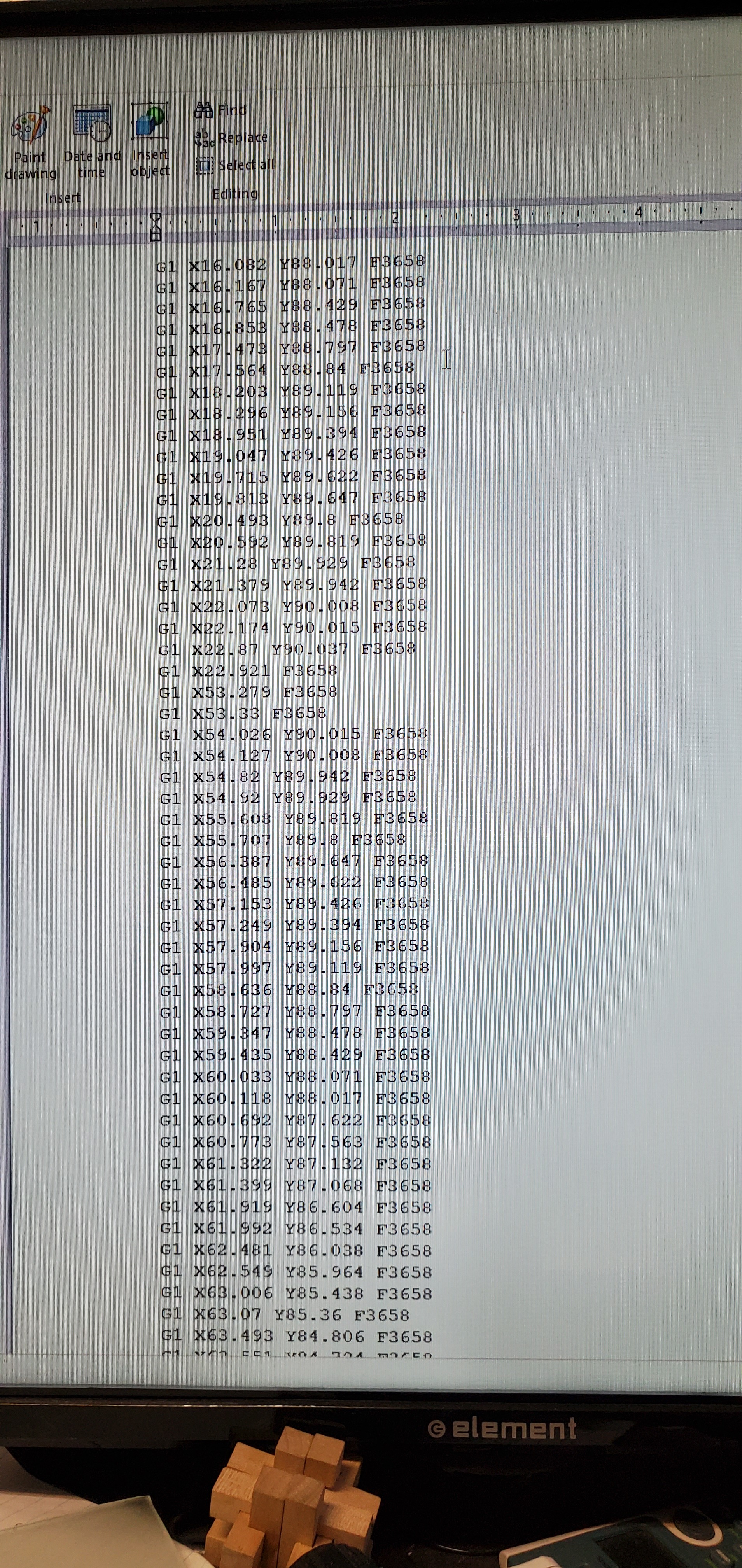
I did have the arcs turned off in the PP, so everything is G0 and G1. I’ve got a picture of some example code from the file because I’m on my phone.
I ran it in the air, and of course no change. Ran from the SD card, no change.
I remember reading where you and Jamie were troubleshooting this, but I don’t have a deep understanding of marlin and had trouble keeping up, especially since I didn’t think the problem affected me. Now that I have some motivation, I’ll try harder if anyone can help me find it again. My searches for “arcs” isn’t helping much.
Well you can try with arcs on, since you have the right firmware. But at those speeds I have never even come close to testing that.
The max speeds are firmware limited but if you bump up against the limit too often the firmware can freak out.
I have limited it to 50mm/s XY, you are trying to run 61 on every line. You will need to make firmware changes. Z is limited to 15mm/s.
1 Like
To give more detail. With arcs off the corners are chopped up into tiny tiny straight segments and the SD/LCD can’t feed commands fast enough ( I think). Arcs on, each corner is one command (smooth arc) vs possibly hundreds with them off.
1 Like
Ok. I’ll give that a try.
No real change. Somehow I ended up with 414 on there for my last project over the weekend. I think it was when I was looking at the controller fan stuff from the old copy where it worked. Now when I enable controller fan, the firmware won’t compile. Whatever. No time for that now.
With arcs, it ran AWFUL… until I noticed the 414 and started scratching my head. Back to the 425, and it ran the same. I played with the junction deviation (0.04 by default) up to 0.1 and the z moves happened a lot faster on my triangular tabs. Min arc length up to 1, nada.
So, when when I send an arc code, the board has to chop it up, right?
Oh yeah, and I think I found my vibration. The rollers (on the side rails) are a bit loose. I still have my first set, and those were loose, too. Then I remembered I was supposed to have some bolts with shoulders. That helped a little, but out came the old tube, and it looks like my DOM is about 0.002 under sized (0.98-1.00). The old mild steel tube was 1.00-1.03.
I’ll definitely pickup the right bolts, and I may print one of the 25mm rollers to see how it fits. I think 0.4mm is just under 0.002", so it should be ok.
Holy cow Turbo! That is incredibly impressive. This is a result I have to live up to.
My business case for this machine is cutting openings for HMI components in electrical control panels, mainly aluminum, but your system gives me hope that one day, maybe, I could cut 12 gauge steel.
I’m gonna be closely following your progress my friend! And maybe asking for advice 
Thanks! The steel was kinda slow going. I got a high quality stubby 1/16 mill so I could get a slower speed, but I want to sort out that chatter before trying such a slim tool.
For the record, this build came about because @viciou said he was curious about what the mpcnc could do at a really small size. I was looking for a new project, and boom.
Worth mentioning that I’m still learning, too.
Only thing to really sort out that I don’t understand is those arcs. I can’t cut metal that fast, so it probably doesn’t matter, though. It’s still fast enough that wood won’t burn.
1 Like
I’ve stored this in my head.
1mm = @ .040” (.03937)
or 0.1mm = .004”, which is the thickness of human hair.
So 0.4mm would be .016”, not .002”.
That’s just in my head.
It’s .0157” if you do the maths. I think you may have a broken decimal point. ![]()
1 Like