Well, it’s been a long time coming. Let me preface my story with that I went with a phased approach to this. I started my build in the Winter of 2023. Fast forward to now, I’m still working on things but only have to adjust my limit switches to get going.
It started out with a ham bone electronics cabinet and a half-a** attempt at making everything work. From the flimsy micro limit switches to the cheap China made STB5100 board that I started with, I’m really happy with where I’m at.
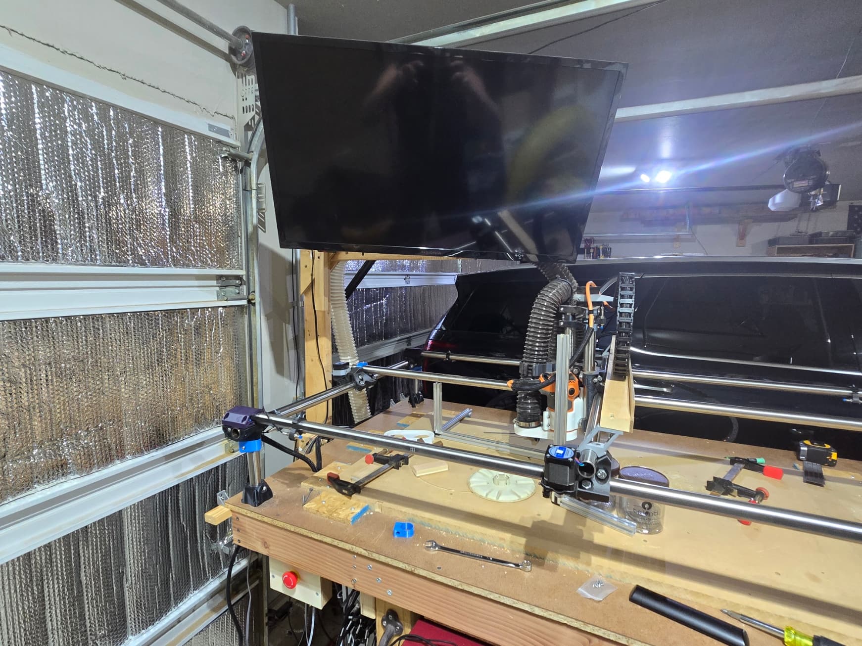
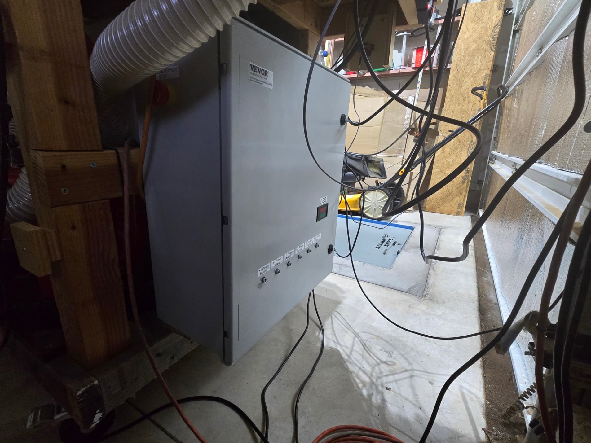
I printed everything out on an Ender 3 Pro, which itself has gone through several iterations of “improvements”. Another topic for another day I suppose. I think I printed every single part at few times, minus the core. That thing was a beast which failed to print twice. It’s been so long since I’ve printed it that I can not recall what settings I used. Recently though, I reprinted the corners with the gyroid infil to then back fill those parts with Smooth On two part epoxy. Other “modifications” include using some timing belt cut off between my 1” stainless pipe to help with slippage, inductive limit switches, a custom built router clamp for my Ridgid R2401 and a fiberglass electronics enclosure for all of the electronics.
I’ll be taking some photos here shortly to get them uploaded. Constructive criticism is highly appreciated. I had 3D printed a bunch of drag chain that just did not work out, so I bought some off of Amazon.
All in all this was a really fun project to take on, regardless of the bill. I suppose I could have bought an Avid CNC for the amount of money I slammed into this project, but I like to figure stuff out and being able to build something with my bare hands made me feel like a mix between Adam Savage and Jeremy Fielding, if only for a few minutes.
Here is my build list. I’ll spare some of the boring details like what type of filament and the settings I printed in.
3D Parts - PLA, some with Smooth On Smooth Cast 326
1” stainless tubing for all frame parts
Standard parts list from the website for all bearings, bolts, nuts, lead screw, etc.
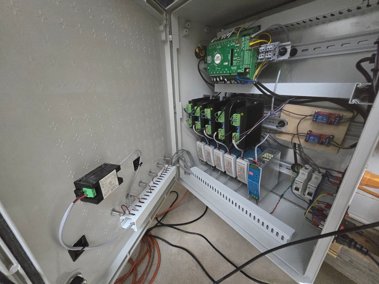
Warp9 Ethernet Smooth Stepper
C25X break out board from CNC4PC
Mach 4 Hobby from Artsoft
Ridgid R2401 router with extended power cord, removed and replaced factory cord
Meanwell 120-24 power supply for the ESS
5 x Meanwell 60-24 power supplys for the stepper drivers
I was running TB6600’s, but recently changed to the China DM542 (these things are super quiet)
5 x Stepper Online 17HS19-2004S1 motors
NPN Inductive Limit Switches
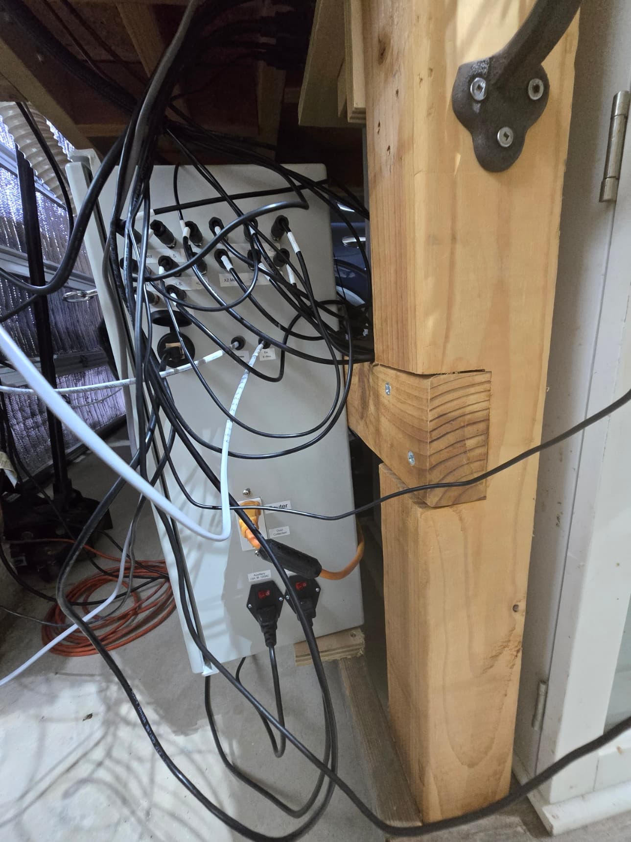
M8 4 Pin, 3 Pin and 2 Pin connectors for the various connections at the electronics cabinet
12 VDC PWM controller for 2 x Cooling fans at the cabinet (still need to install)
Shielded CAT 6 bulkhead connector for connection between the ESS and PC
Beelink EQR Mini PC with dual LAN (One is set to the ESS network on static, the other for web/RDC)
DIN Rail for the cabinet
3D printed custom DIN rail mounts for the power supplies and accessories
Digital Ammeter/Voltmeter for the ESS PS and accessories (Dust collection/Router, still need to install)
LEDs to show power at the power supplys
Open slot wiring raceway to keep the cabinet tidy
I also added 4 electrical circuits to my load center. 2 x 15 amp and 2 x 20 amp. The 20 amp is on a single throw double pole breaker to shut everything off in the event it hits the fan
Operator side E-Stop, with a far side E-Stop built into the Cabinet
Internal breakers to the cabinet
Fused AC power for additional protection
FireTV mounted above the table
3D Printed, custom dust shoe (still a work in progress as I can’t find brushes that are soft enough)
I’m still in the process of settings things up but the last items are settings the distance from the corners for the limit switches and getting those dialed in. I was also able to get the frame square today, which was a huge win for me as the previous build I could never get square.