A few steps forward and one large step back.
I made a lot of exciting progress on this project but then I broke my MPCNC. With my limited time that I can spend in the garage I am not sure when I will be able to get it fixed. It’s just a wiring issue for one of the Y steppers but that will take time.
Exciting progress. Here is a list of the features I have added since I last posted.
Named the machine
- Instead of calling it “My Core XY” I now call it “Timber Bot”
- Cool logo to laser engrave onto the side to follow
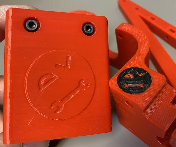
- I added my personal Tinker Man Logo to several of the 3D Printed parts
Parametric Design OnShape Document
- The Entire machine model size can be controlled by changing three variables in the document. Three Variables are X Rail Length, Y Rail Length, Z Rod Length
- CNC cut Wood pieces scale to fit the variables
- Assemblies (Renderings) Scale to fit the variables
Added wooden box frame ← not tested yet do to broken MPCNC
- All the pieces fit together with simple joints
- Glue together rather than screws or angle brackets
- Holes for screws, cables and zip ties
- Uses 12mm wood (11/32 inch)
Changes to the Core XY
- Added Mounts for X and Y Endstops
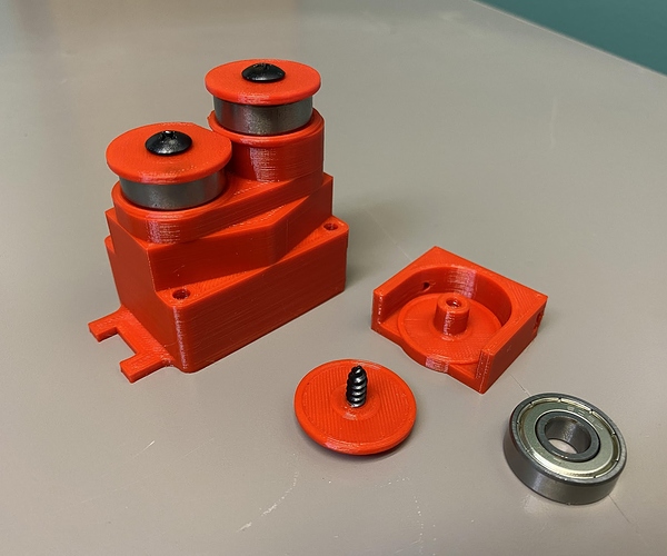
- Changed out all the 3 mm bore Idlers for 608 bearings. (Special thanks to @dkj4linux. David’s Idea of the axle and hubcap design were Instrumental. See details below)
- Added more space for the tool head
- Added more space the rollers to move past the ends of the linear rails. (See below for details)
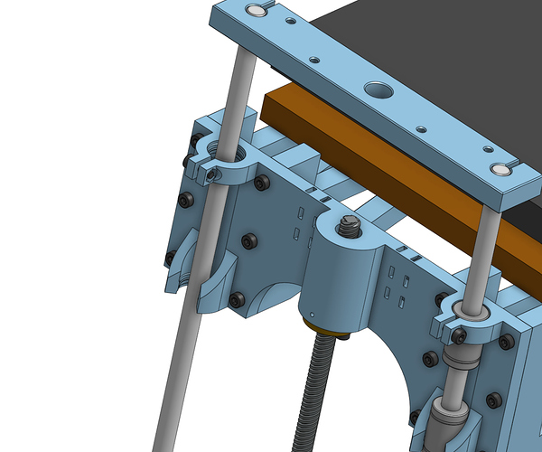
Added full Z axes
- Uses Leadscrew instead of belts
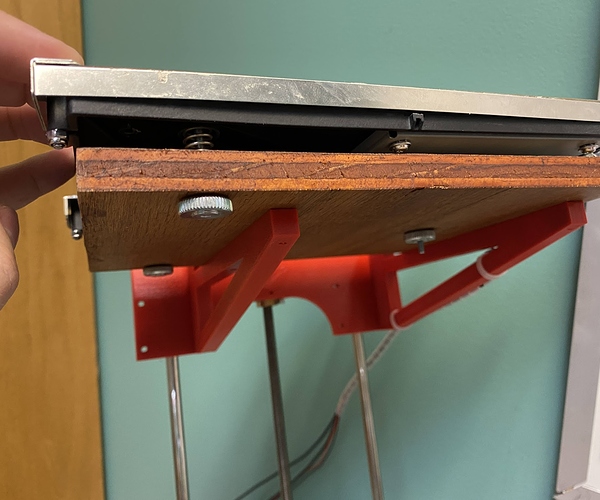
- Versatile design to fit many bed sizes & configurations. Uses a CNC cut wood piece to mount the bed to (See below for details)
- This is a single motor build so it can probably only handle beds up to about 250x250. I’ll eventually test it with my 300 x 300 to see if I will work.
- Smooth Linear LM8UU bearing motion (THIS IS FREAKING HUGE!!! See below for details)
Now for some of the details.
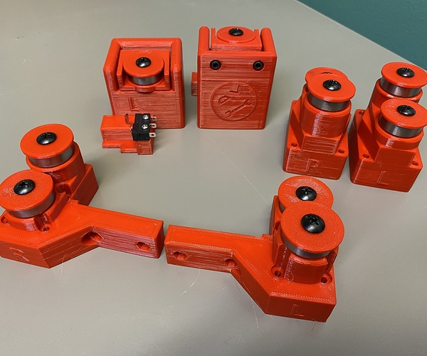
Some of my ugly Tinker man logos. Maybe I’ll eventually replace them with the Timber bot logo I am thinking about.
How to adjust the size of the Timber Bot
https://youtu.be/IUe8MdWHR5c
When I started working on this project I wanted to use 608 bearings but I couldn’t think of an easy way to implement them. So I bought some idlers with a 3mm bore. Bad idea. This actually complicated the design and made the build process even harder. Well copying David’s idea of how he uses 608 bearings on his core XY laser engraver made things really easy. It made the build bigger. Takes up more space but it is SOOOOO worth it. Much easier to design, print and assemble. They are also a lot stronger. Thanks again David.
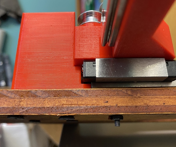
I noticed that the Linear rails can move about 7 mm past each end before any of the ball bearings leave the steel track. So I made the plastic blocks on the ends give them an extra 5mm of space. This way I gain an additional 10 mm of movement on each rail.
The Bed Mount has up to four braces. In this photo I chose to only use two that won’t conflict with the adjustment screws. I think this is a very versatile design. It should be able to mount up to many bed shapes and sizes. You will need to make your own custom wood piece. Later I will make one for my 200x200 bed and try another one for my 300x300. (210x160mm bed pictured)
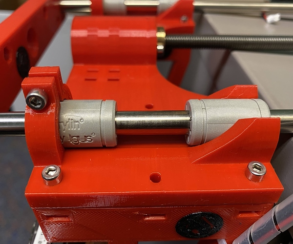
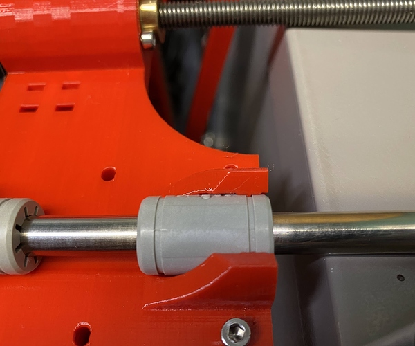
I am EXTREMEMLY PROUD of this next one. I have tried to design MANY machine parts that hold LM8UU linear bearings. The biggest problem is that FDM 3D printing has so many imperfections that the bearings don’t ever line up perfectly. My first version on this Z carriage was horrible. I don’t have pictures but when I put two bearings in it and tried to push an 8 mm smooth rod through it … well lets just say it was very difficult to push through. Think hammer as a solution. So I finally came up with an idea that solved the problem. It removed about 95% of the friction caused by the bearings not lining up. Instead of trying to hold the full length of the bearing in a 3D printed sleeve I only hold about 4 mm of each bearing. So they can be held firm but will still be able to aim. This makes it so they can very easily align with eachother. I am super happy with how well it works.
In this next photo you can see how I tight clamp the top of the upper bearing and then loosely clamp the bottom of the lower bearing. This will prevent a heavy load on the bed from causing the carriage to lose it’s grip on the bearings. That should prevent the bed from getting out of level during a long print.
If you look close (zoom in) you can see the 4 mm wide section that holds the edge of that bearing into place. The upper clamp has a similar design.
Well that is all I have for now. Until I get the MPCNC working again I can’t cut the wood pieces to test a full build. It may take me a few weeks to get another update. I have updated the original post with a link to my Google photo album if you want to peek at a few other images I have taken.
