My new DIY machine build.
I wanted to build a smaller machine as the one I normally use is too big for most of the things I make on it.
Also I wanted to improve a few things and add some extra features that would be hard or even impossible to add on my old machine.
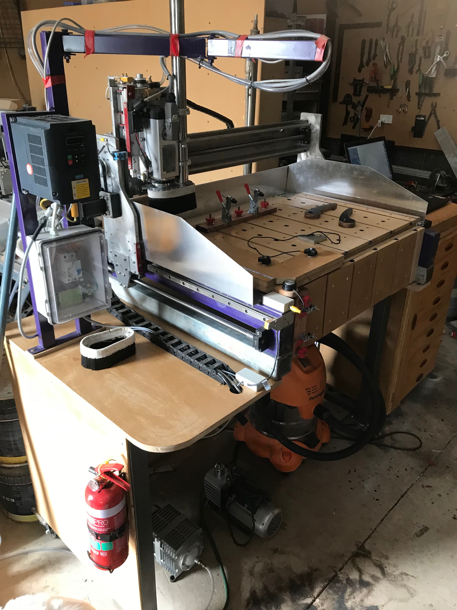
I started off by building the main frame, which is made of steel and fully welded. This gives a stable base to build the rest of the machine.
I used a piece of 100mm wide aluminium channel for the gantry beam, to which I fitted a pair of Hiwin linear rails and 1605 ballscrew. The ballscrew is driven by a Nema 23 stepper motor that has a reduction of 2:1 to increase the torque of the motor.
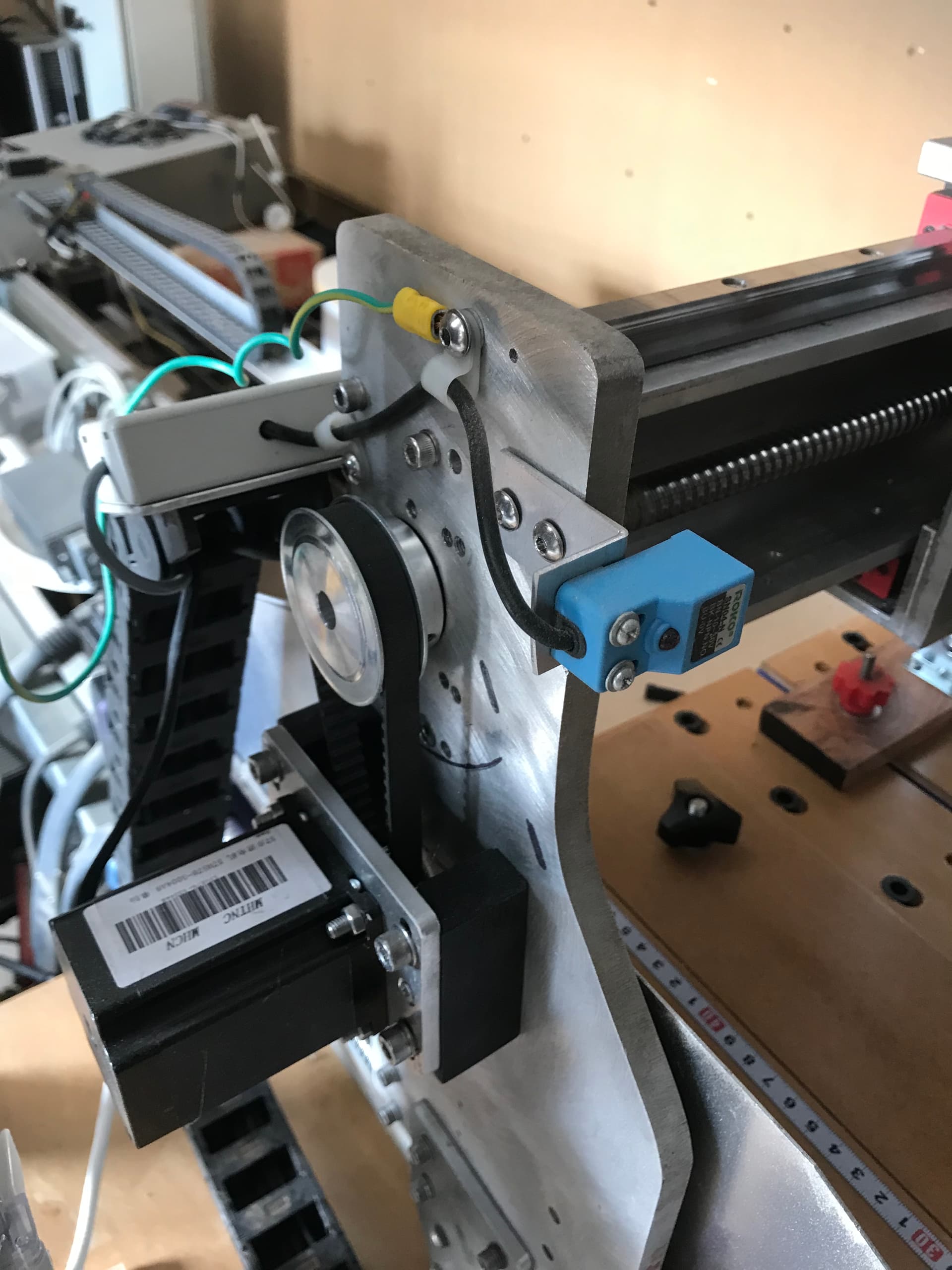
I did the same for the Y axis, a pair of Hiwin rails and a pair of 1605 ball screws, motors both reduced by 2:1 using 15T and 30T timing pulleys.
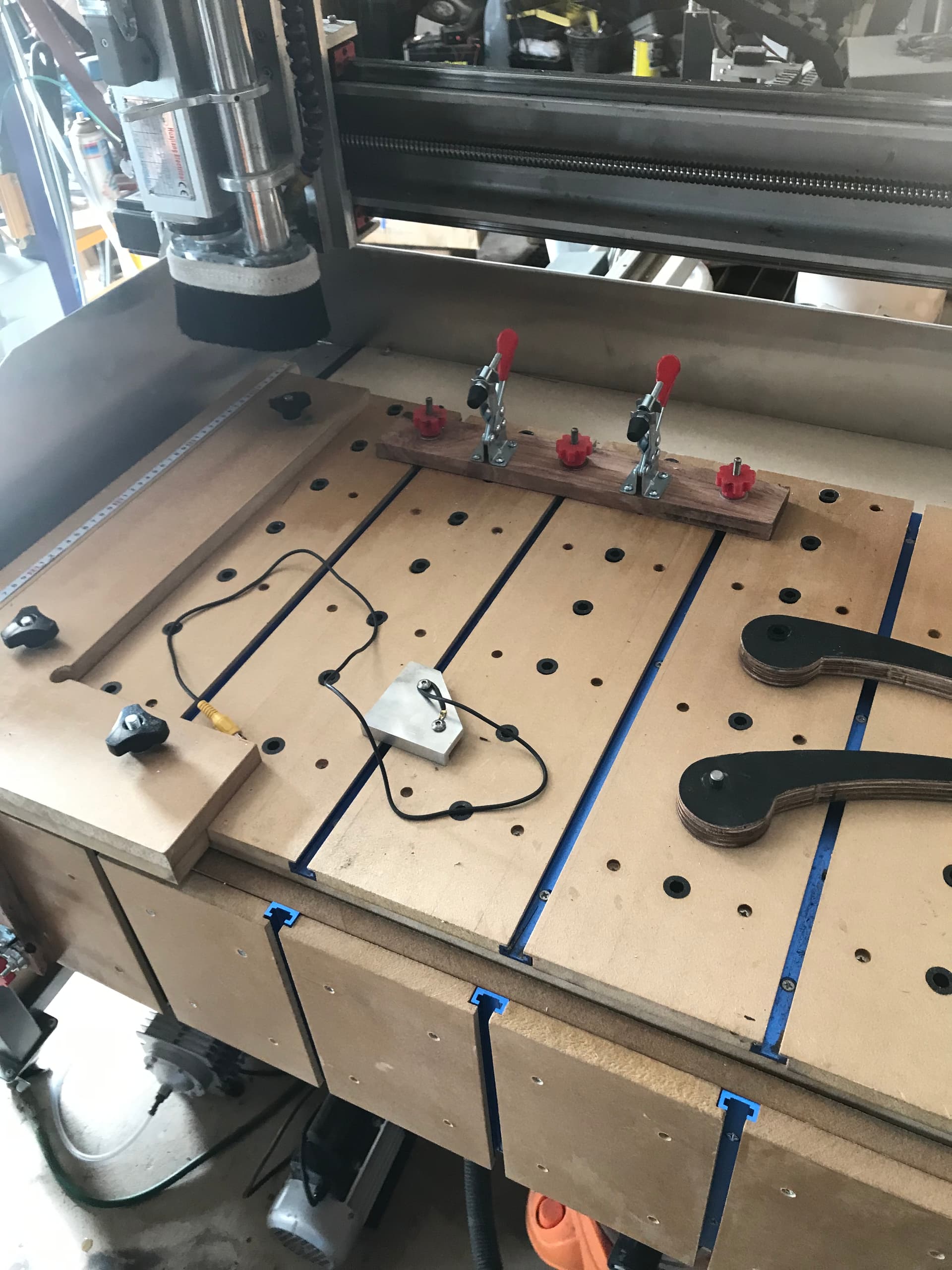
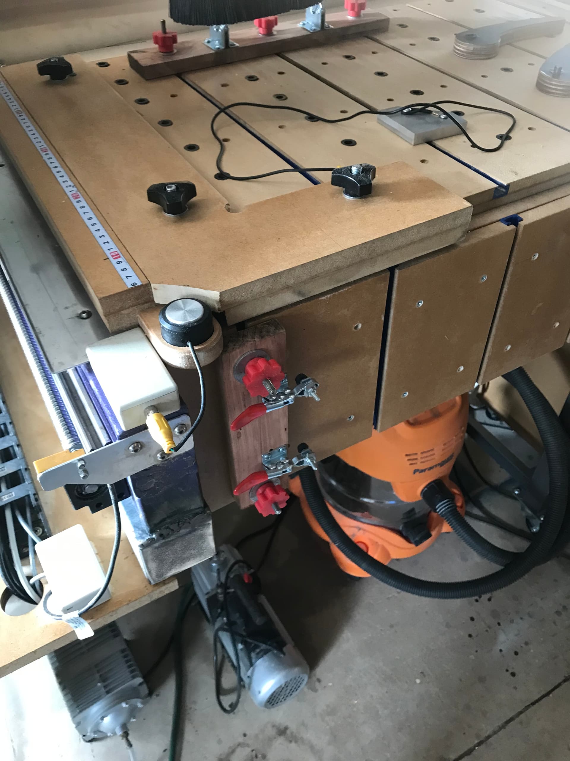
The bed has aluminium T slots fitted to be able to use various hold down methods, but also in between the T slots are delrin bushes that have an 8mm hole that I can put a stainless 8mm pin into for using as stops, adding wooden cam clamps and other positioning gadgets.
I designed the main frame to have extended travel for the Y axis, the reason for that was to be able to build a vertical table in front of the machine for doing dovetail work and end plank work etc.
The Z axis also has Hiwin linear rails and a 1204 ballscrew. The stepper is also 2:1 reduced.
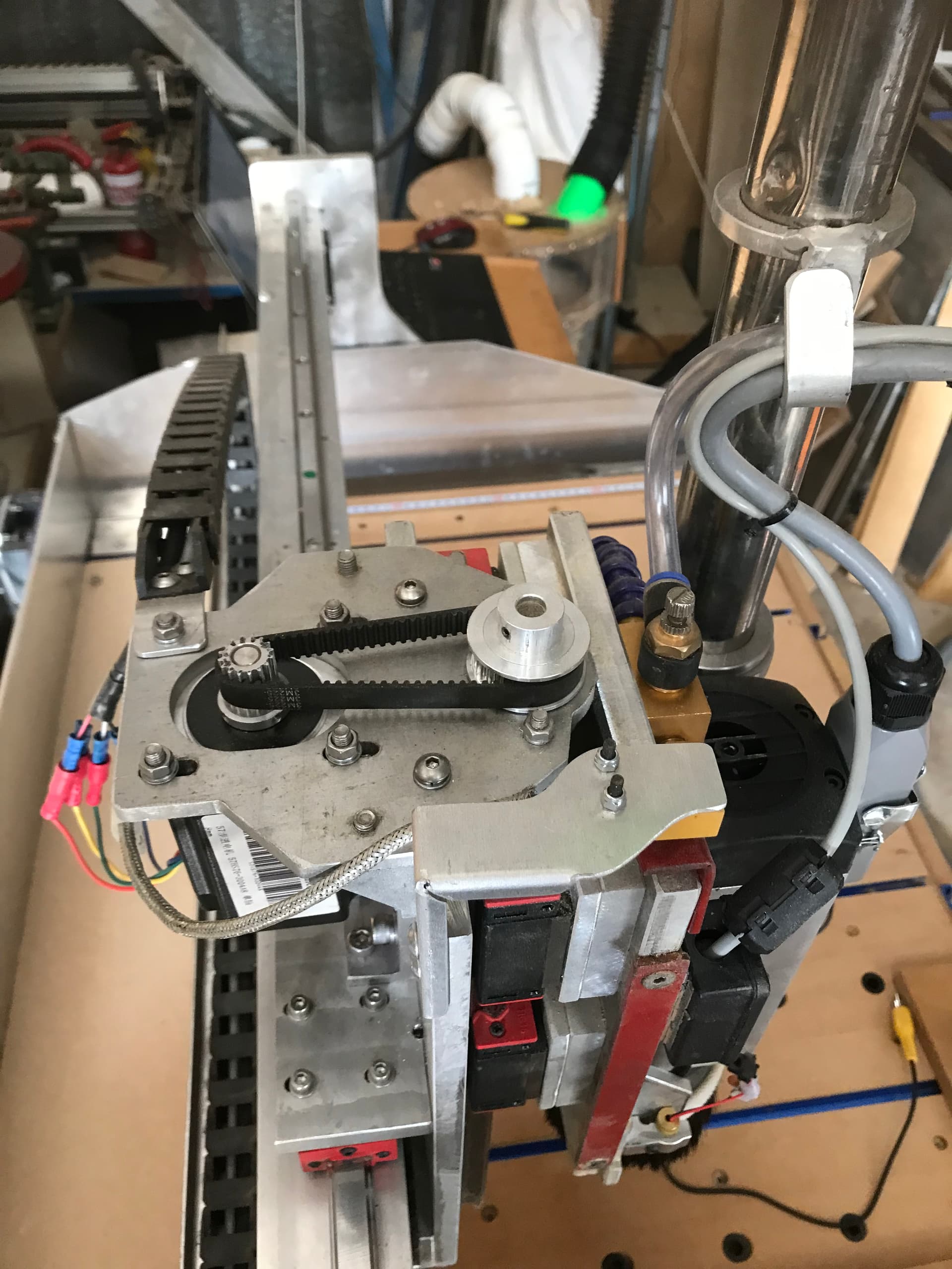
The spindle is a VFD controlled 1.5 Kw air cooled spindle with E11 collect chuck. I would have liked a bigger ER, but that was all I could find at the time of buying.
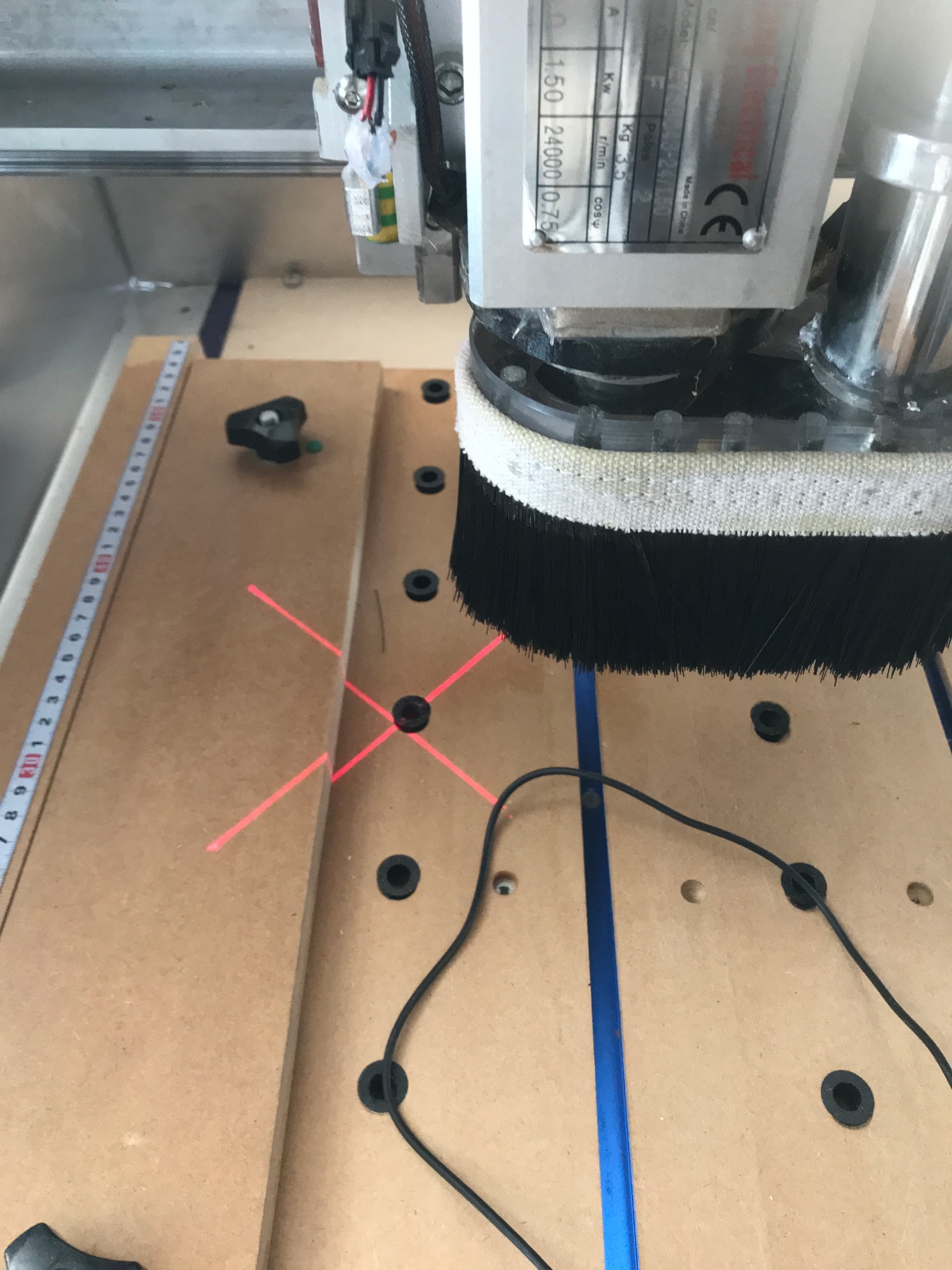
It has a builtin dust shoe that travels up and down with the Z axis. The shoe has magnets that allow easy changing of the dust shoe brush. As I use different size cutters, I can change the shoe brush to suit the length of the cutter being used.
The main body of the dust shoe is made from 10mm acrylic and is clear. Above the dust shoe head is a round ring LED fitted to the spindle to shine light onto the work area when needed.
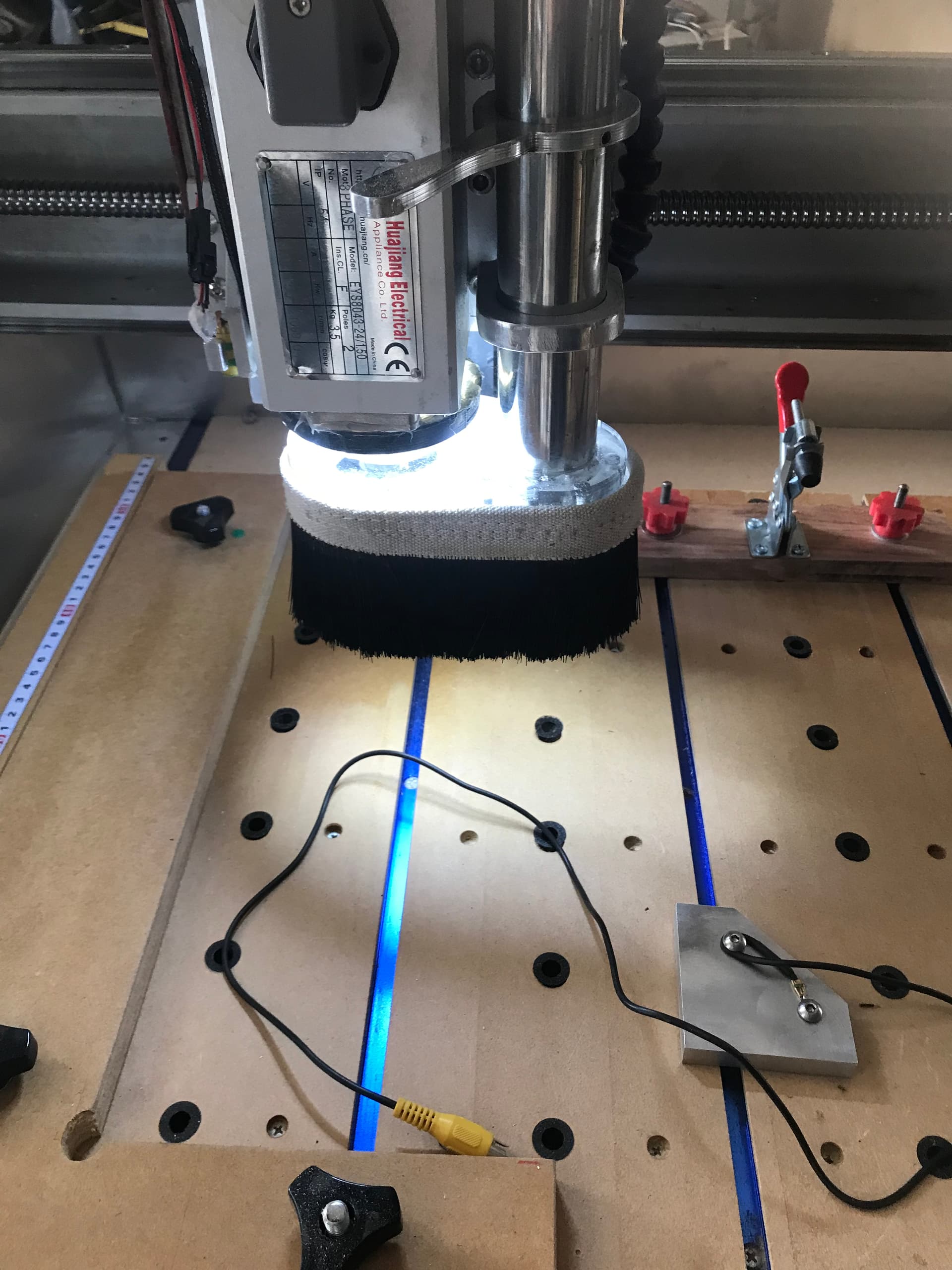
The Z axis also has a laser crosshair fitted that I can use with macros to position the cutter easily. I use that mainly for doing keyholes in plaques and things that need to be hung on a wall etc.
I have mounted a tool length sensor semi permanent to the front of the machine, for doing tool change measurements. I say semi permanent because it can easily be lifted off when needed to fit the fence that goes on the main table for some setups. It can then be put back again when the fence has been fitted.
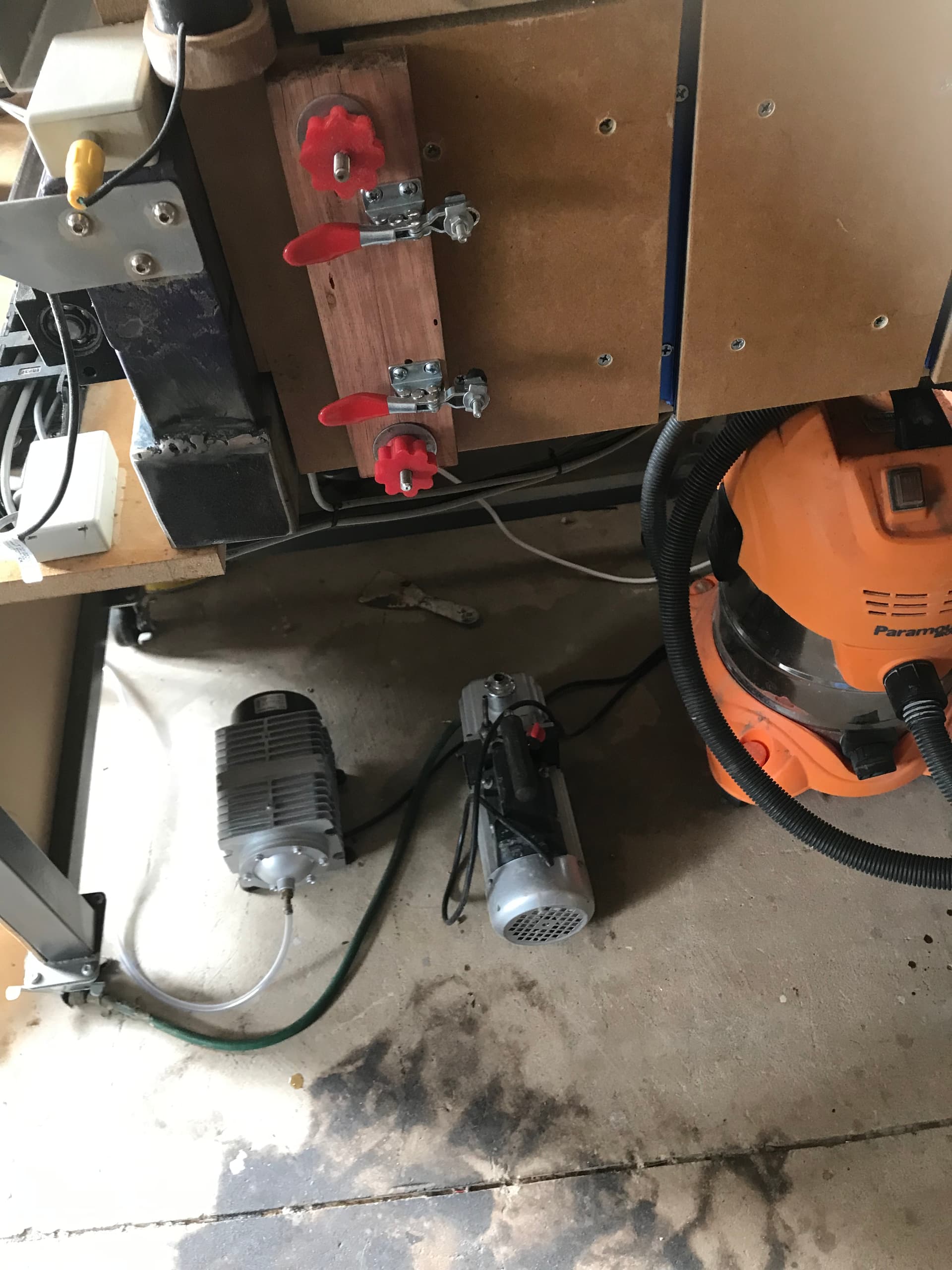
I have a mist system that can inject a small amount of cooling fluid with the air flow when needed, this is fitted to the dust shoe top and can easily be removed and adjusted as required. A high volume diaphragm air pump is used to supply the air when wanted and is kept below the machine with the vacuum pump that is there for the vacuum table. Also there is a shop vac under the table as well, that can be used for general clean up after a job.
I also designed and built a dust collection system using a large blower that I had left over from a fume extraction system for my CO2 laser. It has a high output of air.
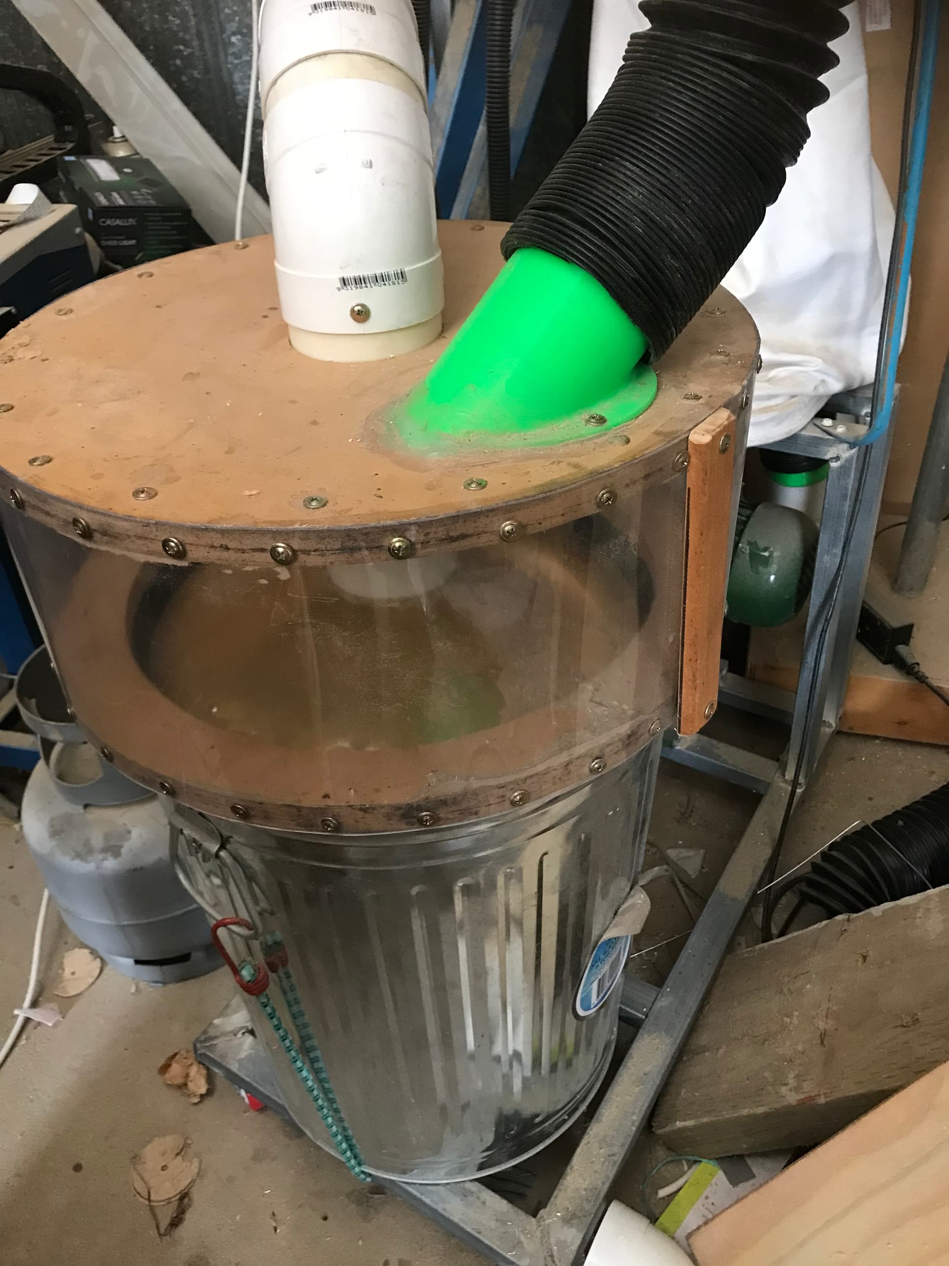
I bought a ready made dust bag that the blower can blow into, and the inlet to the blower is connected with a 90mm hose to the dust separator.
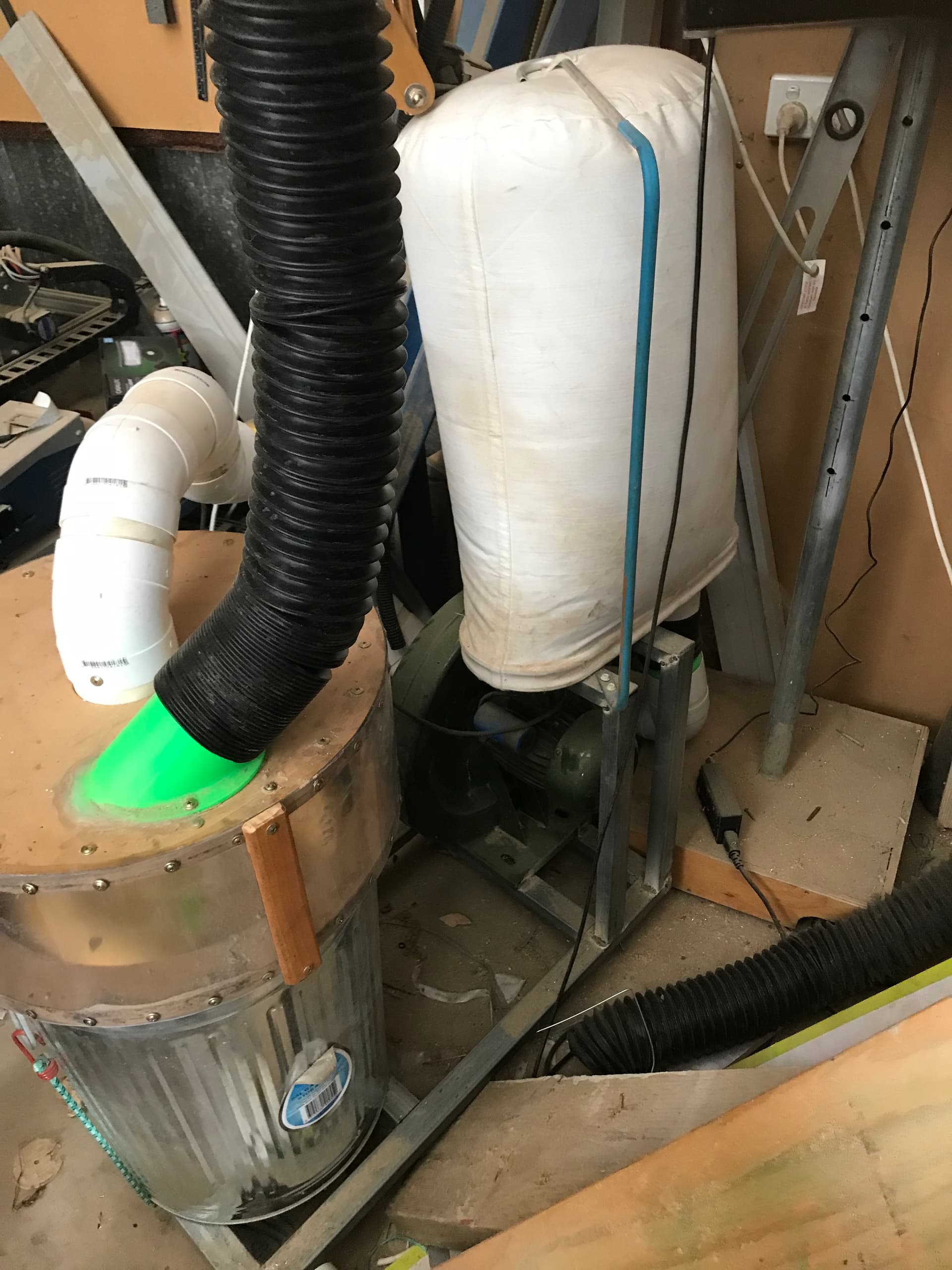
The separator is fitted on a metal dustbin A metal cone just a bit smaller than the diameter of the dust bin is held in place leaving a gap around the outside of the cone to allow the dust to fall inside the dust bin. The 90mm hose connection to the blower goes through the centre of the cone to the inside of the dust bin, causing a suction on the dust coming in and drawing it down into the dustbin. Any dust that is not caught by the cone is collected in the cloth dust bag at the blower outlet. I have never had to empty the dust bag so far, it has always been empty.
This last week I have done my first test cuts with the new machine. I am still learning many things, but so far I am happy with the end results.
Here are a few samples that I have done. I am still learning many things, but it is fun.
Vacuum table I am still working on that.
Sensor plate can be seen in some of the above photos
Plywood cam clamps also in above photos
L shaped fence. in above phots
Tool racks. Still working on those.
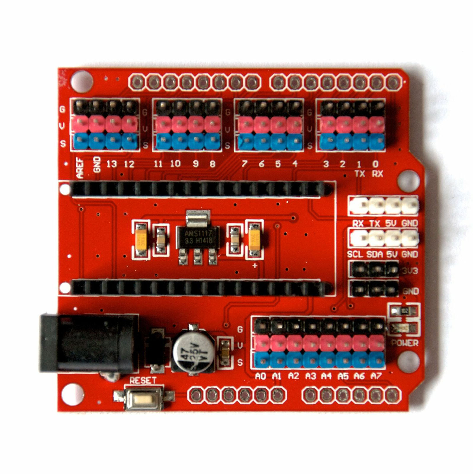
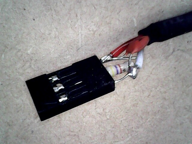
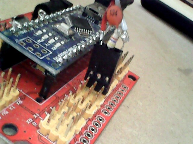
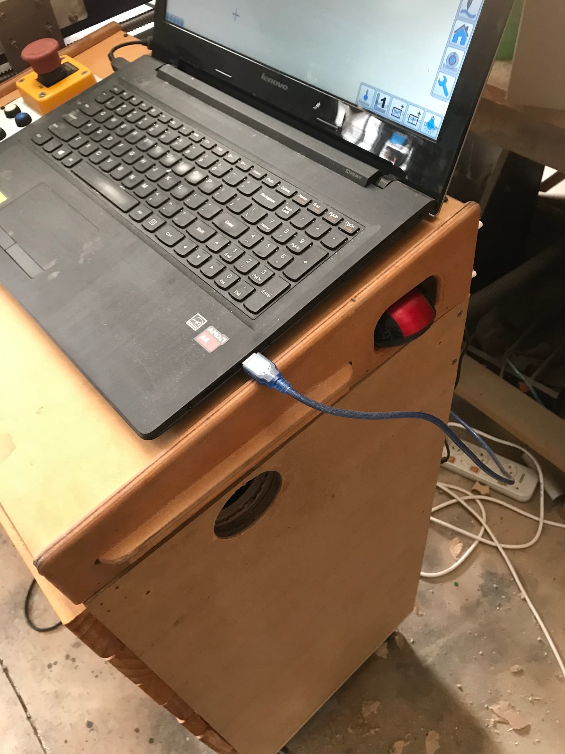
Electronics console and draws.
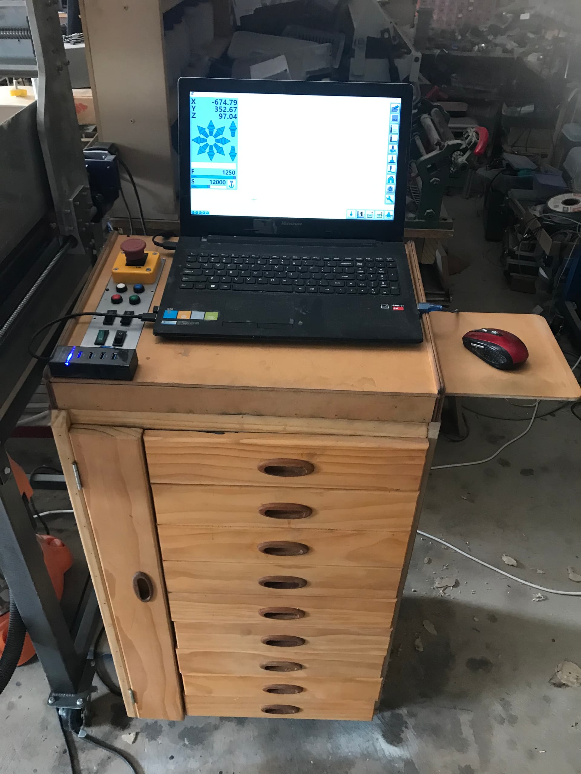
The mouse pad can retract out of the way and there is a pocket hole to put the mouse in.
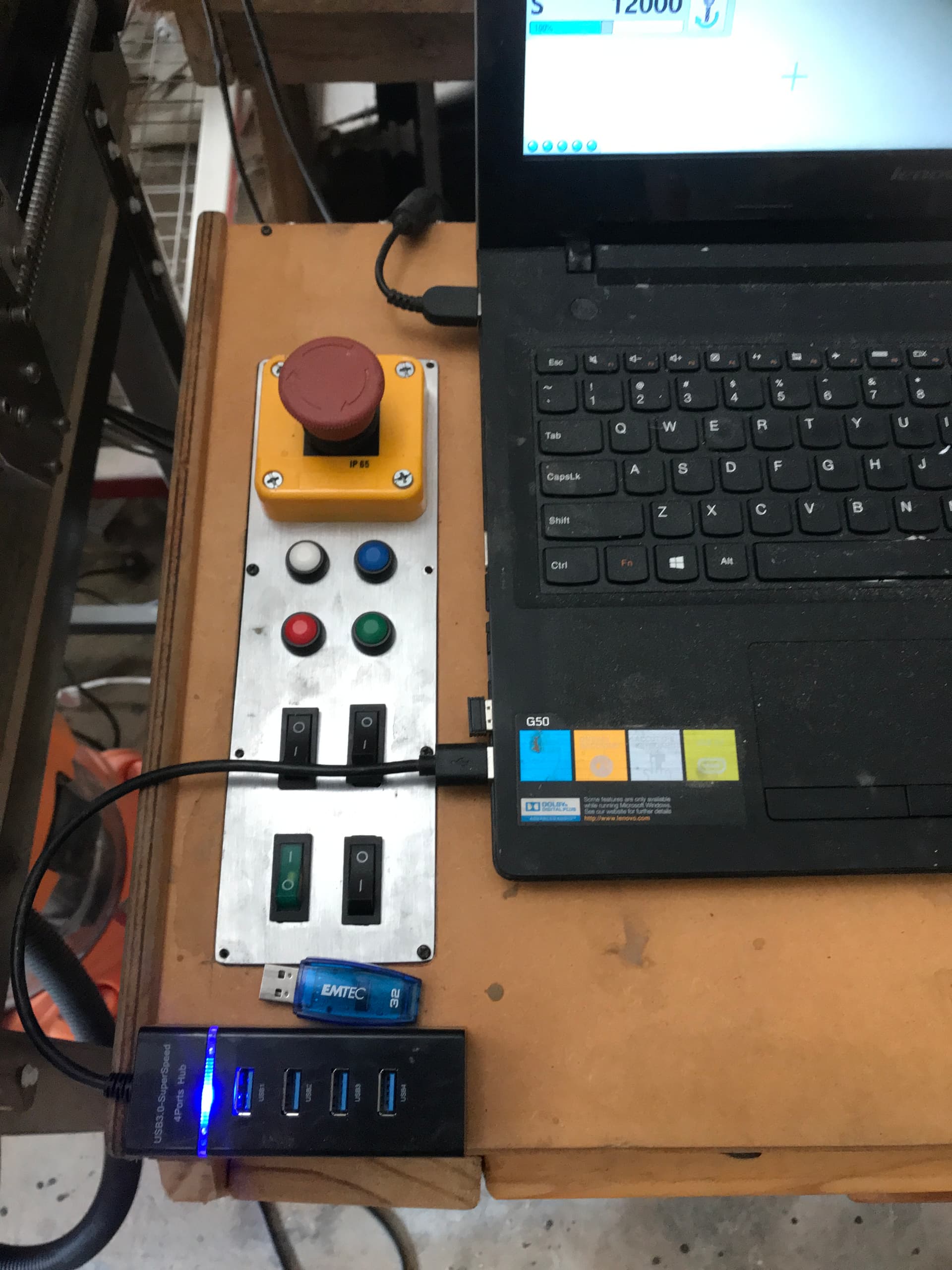
The console panel has some extra switches to turning on the various pumps as Estlcam only has two outputs available which I am using for the LED and the crosshairs.
I may make this panel again and engrave some text on it to indicate what the buttons and switches are for.
Some carvings and engraving tests.
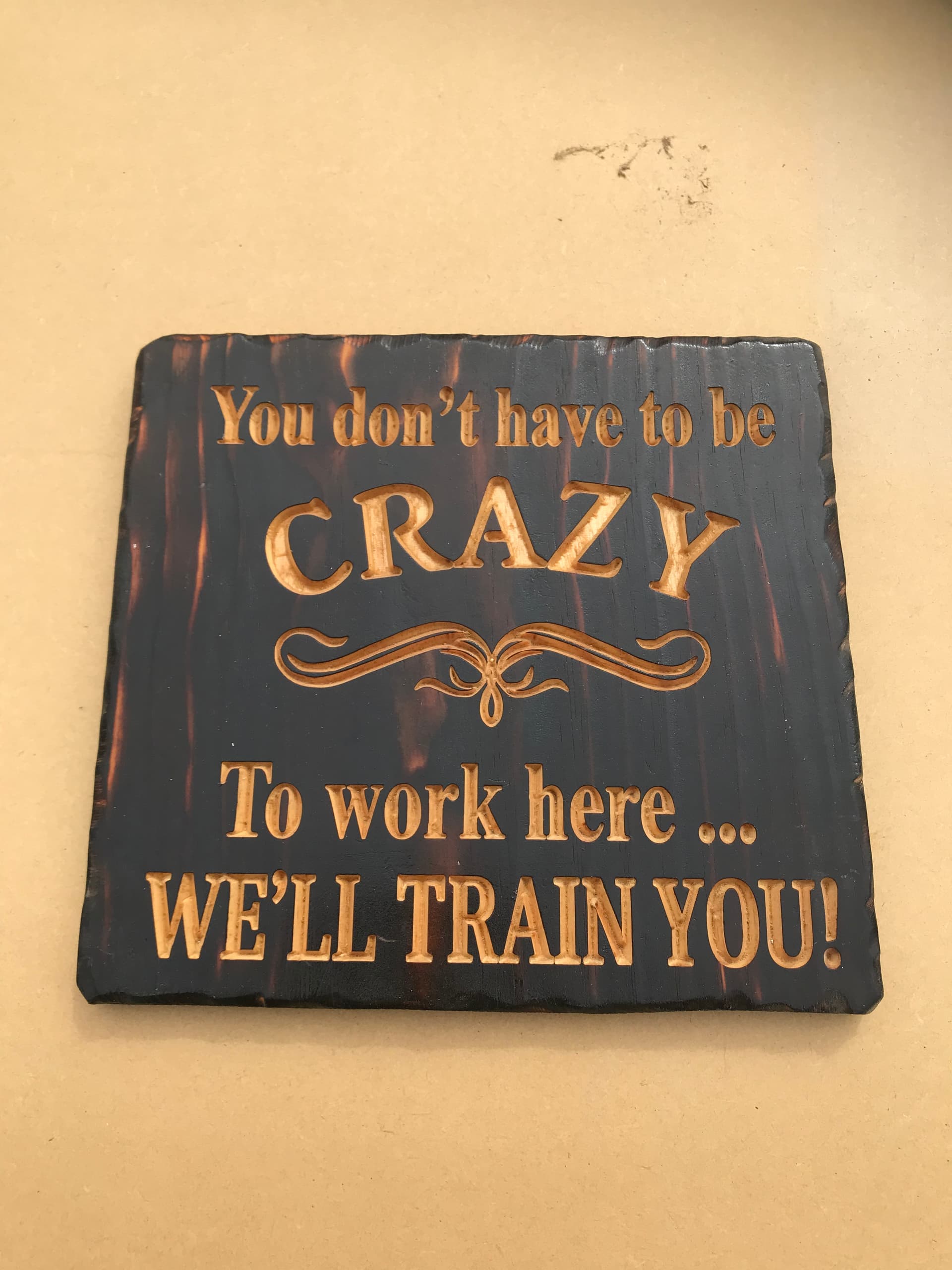
I have to learn how to clean the bottom of the carving a bit better.

3D carving tests.
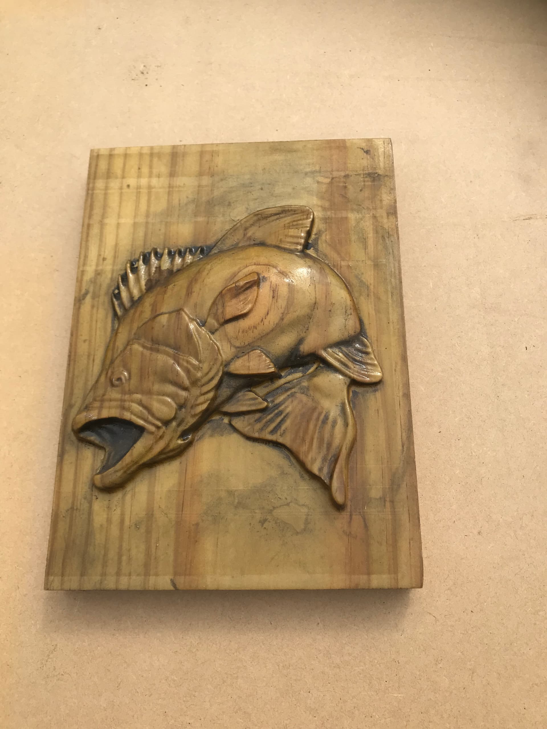
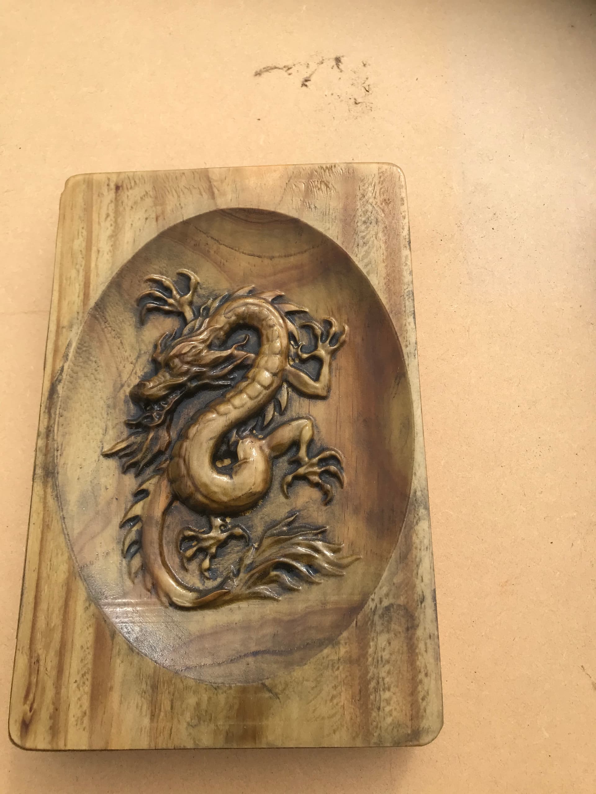
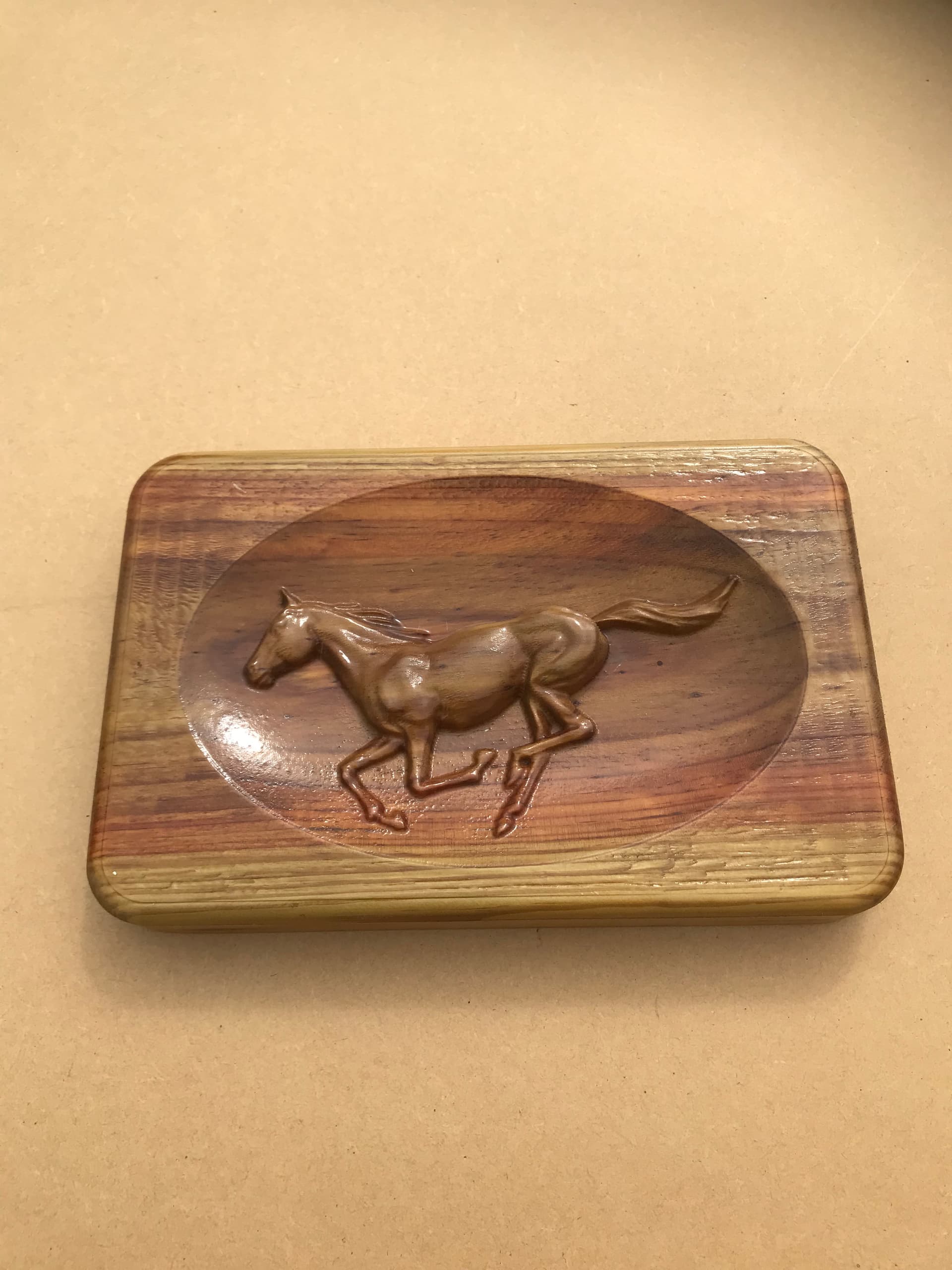
I will test some more as I have time and post again.