Hi all,
So I’ve started the great accumulation of STUFF to build the almighty LowRiderV2.
What a mission… I’ve decided to build a sound proof housing before all the parts arrive. This housing will be built directly under my kids cubby house. I know you’re probably already thinking, Woo… bad idea but hear me out… I live in a relatively small bedroom apartment. The original plan was ot have the LR2 in the kids room mounted to the top bunk bed (with sound proof housing in place ) so I feel at least moving it outdoors into the back yard is a better option.
The sound proof housing will be locked ( a child proof lock ) The lower level of the cubby house is 1.2m H with 1.7m length walls. The base will roll in and out for easy access.
I just spent the last two nights sourcing old carpet from a local housing renovation. They had loads of great off cuts that I can make use of for sound proofing. I’m not sure if I’ll use foam from a bed matress or polystyren foam as an insulator ?
A Makita 1/4 router arrived last week with a few bits and now I’m looking into purchasing a shop vacuum… but am not sure how much power is required to suck up the dust … any thoughts ?
I’ve printed all the parts as well … they turned out really nice 30% fill 0.2… @ 55speed. PLA+ on an Ender 3V2 I ahve it hooked up to a Raspberry Pi 4 and Octoprint. I’ll do the same with the LR2 for monitoring… I’ll also post a fire extinguiser close by.
I’m learning 360 Fusion at a rapid rate… assemblies , threaded nuts / bolts / and manufacture settings… Sure hope we get a Fusion 360 LowRider setup in coming weeks / months… please Ryan
I’ll post a pic. of the area under the cubby house I intend to use to help better clarify things.
Sounds fun and like a good way to make use of some wasted space under the cubby. Be sure that whatever the table size is that it fits in your planned enclosure too.
I use a fairly big shop vac for my lr2 and it does a good job with the collection but big chips will escape as they fly out too fast for the suction. Shop vacs are quite noisy though so if quiet is a goal that may require an alternative. I tried an enclosure on one and it made a pretty good difference on volume.
Good luck with the plans. The cnc’s are great fun.
Hi Brent,
Thanks for the reply… Yeah I’m really unsure as to which SHop Vac. They vary in price so much and I was surprised that some sell for $4K+ I’m looking to spend circa $3-400 on a vac. I also plan to make a small hole in the floor of the cubby so I can pass the vacuum tube down into the sound proof cnc enclosure. This means I’ll need a 2nd enclouse just for the vacuum. (not a big deal).
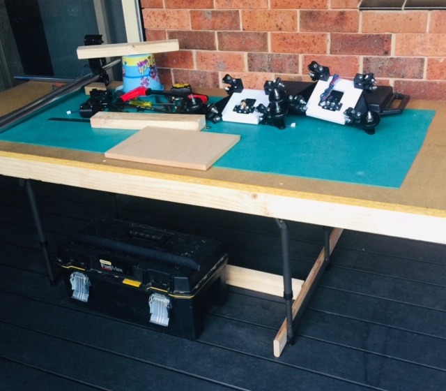
worht noting… I have no work bench. I’m looking into building something to run a track saw on… something similar to the Kreg ACS Here in Australia Kreg is not cheap… so I’m thinking along the lines of adding T-Slots running along the table to clamp material. Just not sure which material to use for the table top… Hard wood is preferred but comes at a price.
Interesting idea. For the top surface being a spoil board I wouldn’t worry too much and go with something cheap and soft as cheap-soft plywood…remember that you’ll be cutting 0,5-1mm deeper than the parts to ensure a full depth cut. I used MDF, and error as it’s too hard, so I decided to add a piece of soft plywood and the attach my work wood onto it…does it make any sense ?!
Show us pics as you go along…might give ideas to others !!!
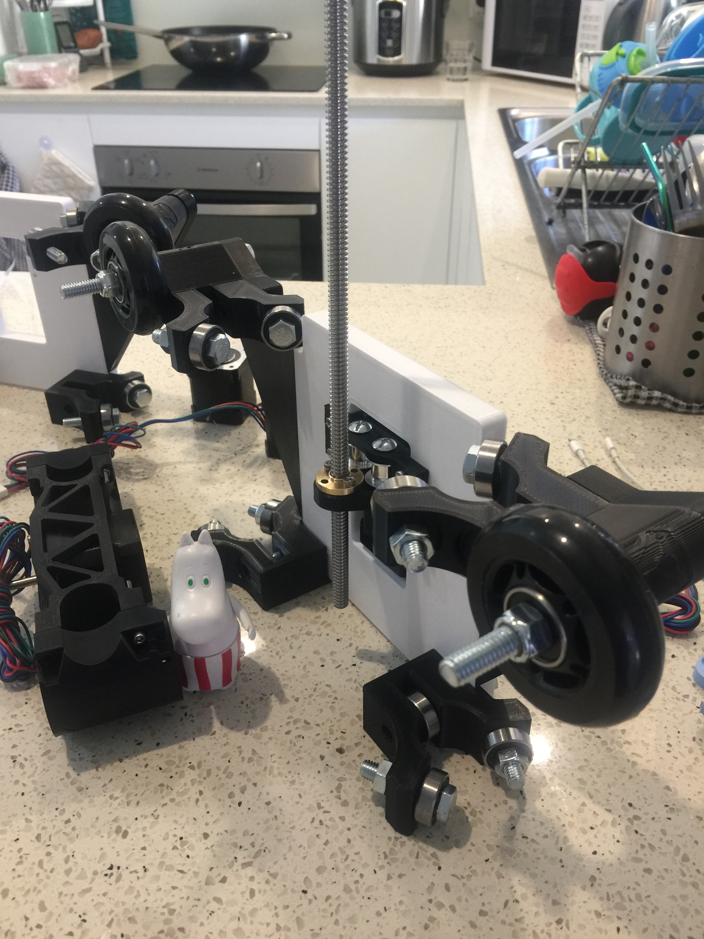
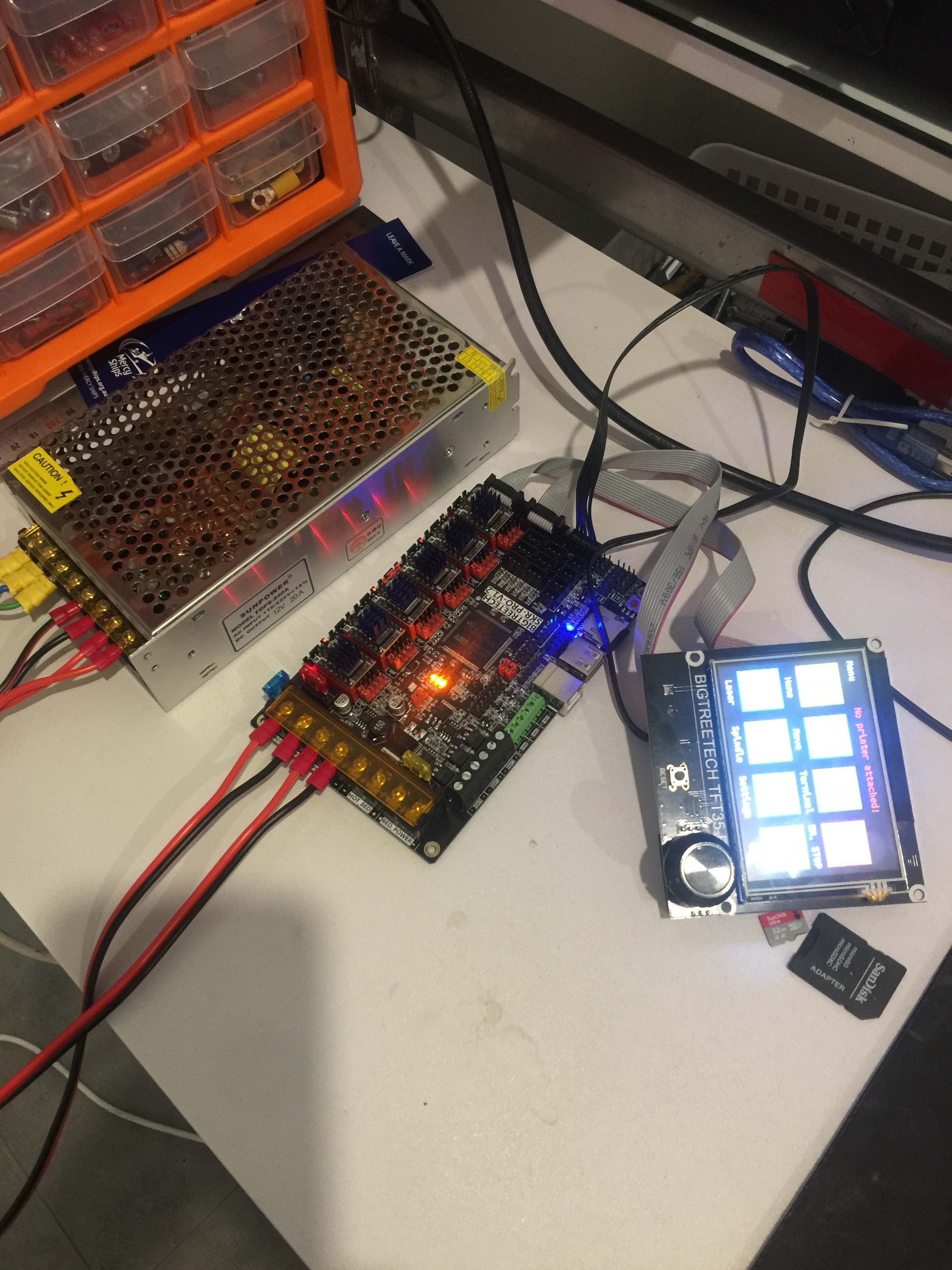
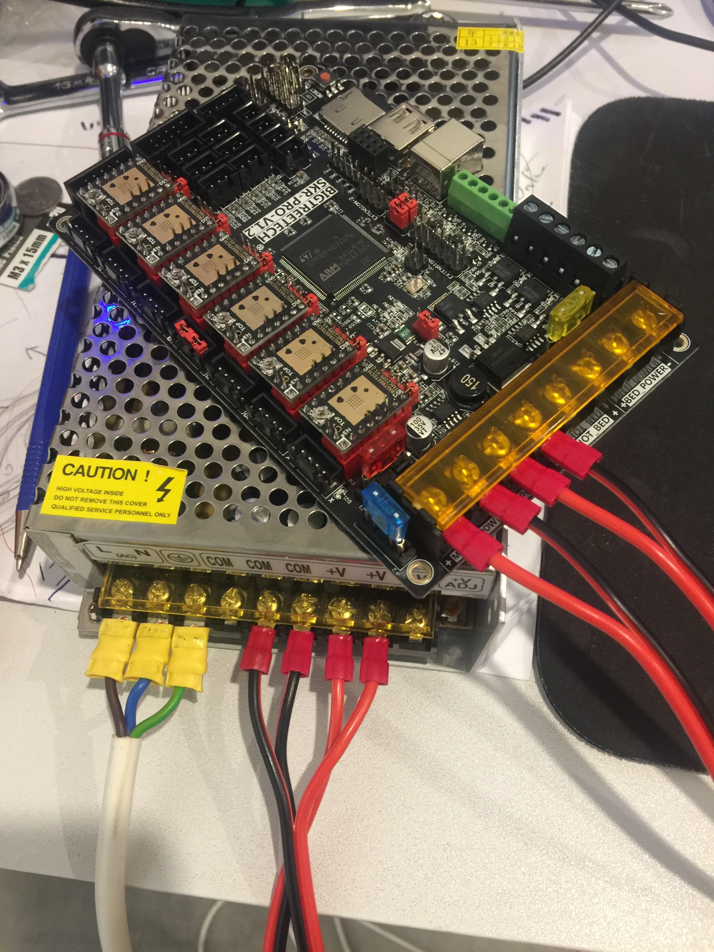
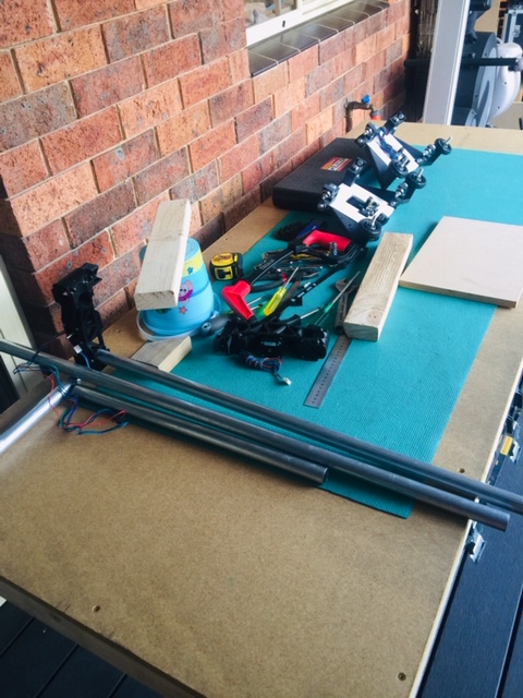
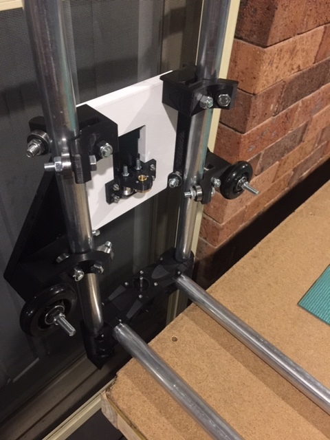
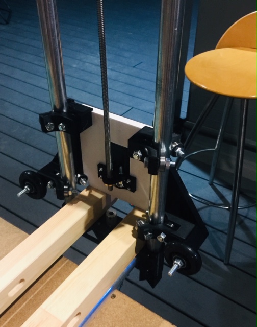
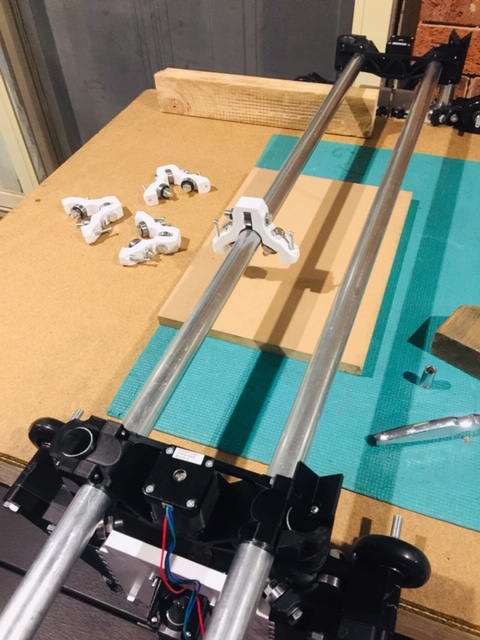
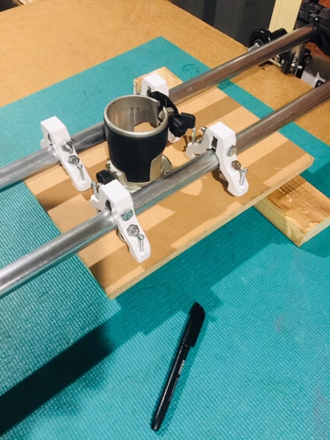
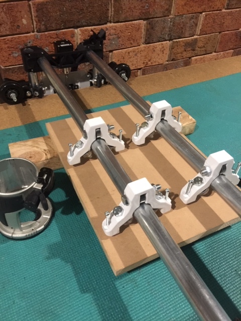
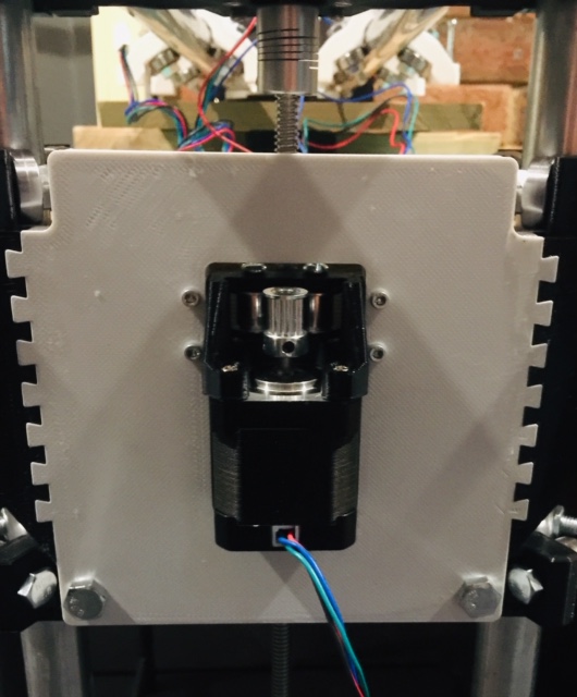
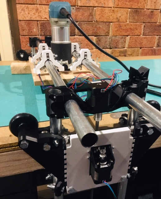
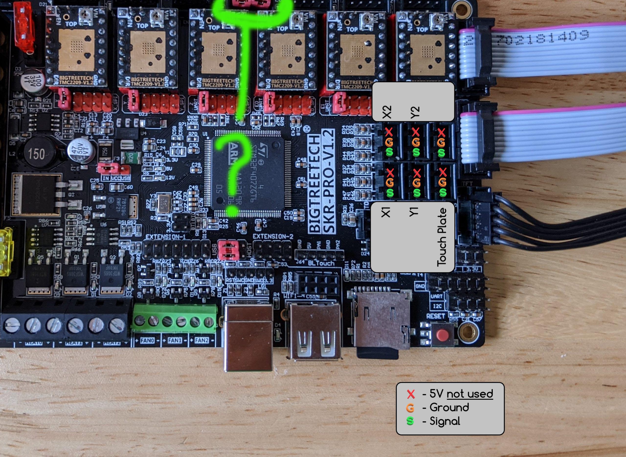
OK so I’ve finally started the build process… all plastics are printed and assembled ( no problems there ) I did have a have issues tracking down the correct size nuts and bolts though. I’ll atttach a few images of my progress to date. I printed the Side plates (Y Axis) rather than cutting them from ply wood. They seem to be extremely rigid. I ahve all my pipe cut and have the BIGTREE SKR-PRO V1.2 board hooked up and poweredon with TFT35-E3 screen powered on.
Next up - The stepper motors (nema 17) I’m finding it hard to track down any walkthru on setting these up as the LR2 docs online only show the RAMPS board. I feel I’ll have no prob. connecting the wires from each stepper motor. The main problem is in the firmware and hooking up seveal end stops.
A lending Hand - Someone got a wee bit grubby playing in the tools… I keep him well away from exposed wires once I turn it on… which reminds me, I gotta print a housing for the power supply and the control box TFT screen.
I NEED HELP please - The documentation gets a little HAZY when discussing the following… it states
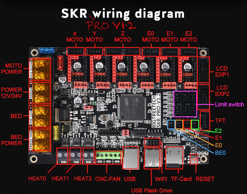
If the firmware is set for EXTRUDERS=0 then E0 becomes X1 and E1 becomes Y2. (or LR would be E0=Y2 E1=Z2) "
What are they talking about in terms of " EXTRUDERS = 0 " ??
The Extruders = 0 directive is built into the V1 firmware configurations already, you don’t need to make any changes for that.
The RAMBO controller was originally designed to support 3D printing, so the ports are labelled with that in mind. The board could support 3 extruders, whose motors would be plugged into E0 MOTO, E1 MOTO, and E2 MOTO. In the configuration, you’d use the "EXTRUDERS = " directive to tell the firmware how many physical extruders you have.
The firmware configuration assumes each extruder includes a motor, a heater, and a temperature sensor. The firmware has a built-in safety feature that won’t move the extruder motor if the related heater (HEAT0, HEAT1, HEAT2) and temp sensor (E0, E1, E2) aren’t within the range of melted 3D printing filament. The Extruders=0 directive tells the firmware that it is okay to move the motors connected to the E0, E1, and E2 plugs without checking the extruder temp (which isn’t there since we don’t actually have a heater or temp sensor).
I really appreciate your clarification on this Tom.
Best I be sure rather than plugging things in ( end stop switches in my case and end up burning something out.
Next Up - I’ll install “Repiteir Host” for windows & plug in each stepper motor.
I won’t wire up the end stop switches just yet. Hope it will operate ok wihtout endstops till I know each motor’s rotating in the correct direction.
IT’s ALIVE !!
I’ve now attached one Stepper Motor ( X axis ) and it rotates when I make an edit in Repitier
Time to do a little victory shuffle dance I feel… Yipee for me !
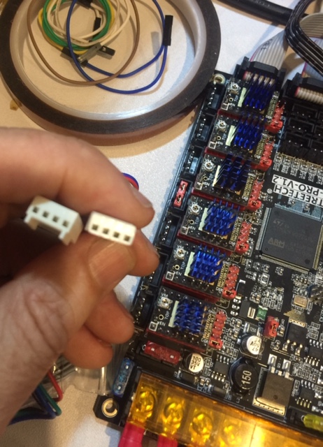
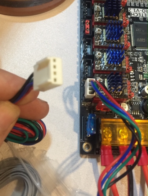
Worth noting : My NEMA 17 stepper motor connnection plugs don’t fit in the SKR PRO board as this is an older NEMA 17 without Dupont (4 pin) plugs. Instead they’re a thicker white plug but with a little hack using a nail file and knife… I kocked off the tabs and filed it down so it fits… a tight fit at that but they do now fit. I htink in the near future I’ll buy a few black “Dupont (4 pin)” plugs.
(below images) show before and after making modification to the white plugs to fit into the Driver connection on the SKR Pro board.
Might have a crack at using a couple of arcade button switches I have laying around from a pinball project I created several months back (PINSIM).
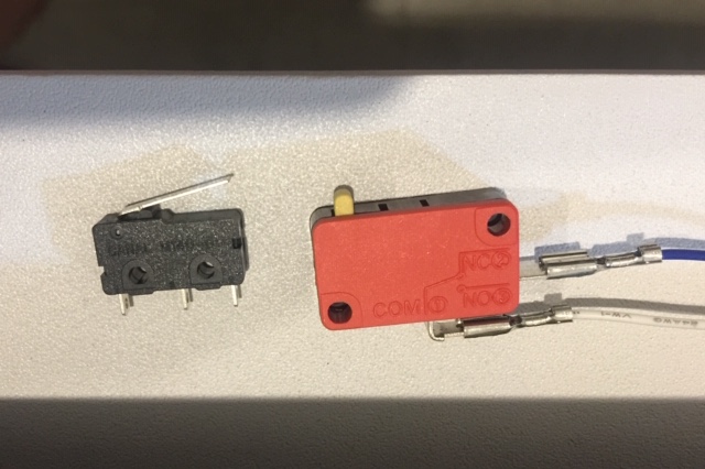
The red larger switch is from the arcade button.
The black switch is from a Prusa i3 Project. I still have three of the black switches ready to go but am under the impression that I really need to use the same size switch on each axis at least for symmetry.
I’m more attracted to trialing the arcade switches as after all this is a fun project… right
If implementing dual end stops, the 2 switches on a single axis should match, but there’s no reason you can’t use slightly different switches on different axes.
If you register with Ryobi (Australia) you get a total 6 years of warranty.
First impressions are that it’s at least as good as the old one, and a little (very little) less noisy. I have replaced the hose with a larger diameter though.
yeah I’ve also been eyeing off the Ryobi vacs in Bunnings. There’s a 1400W one for $195
Might do the trick I feel. ( or the Makita for $385)
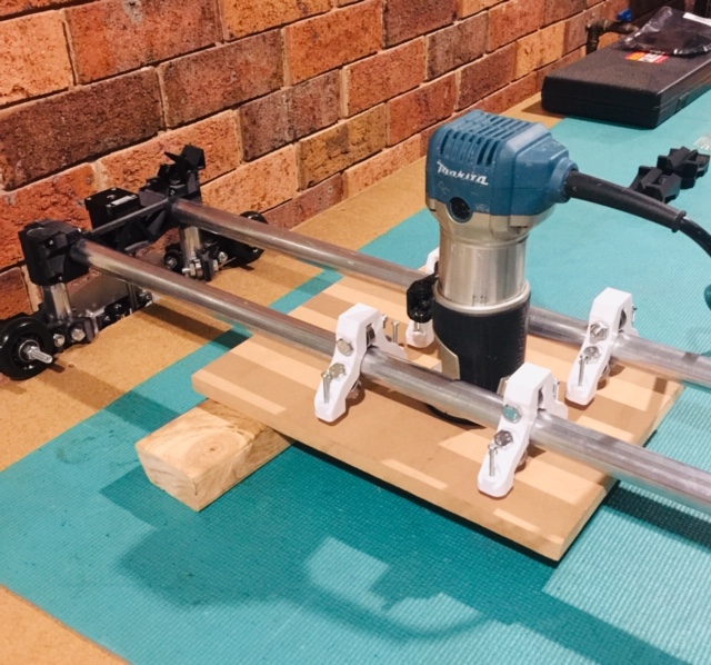
My Makita Router came with a clear dust extraction cover sleeve that fits on the side of the router sleeve. I tried it on the LR2 gantry but the exit tube hits the X axis steel pipe. I am thinking I might cut the clear plastic and reroute it under the steel x-axis tube.
Any minute now I will finally fire up my monster… feeling a lot like Dr. Frankinstein.
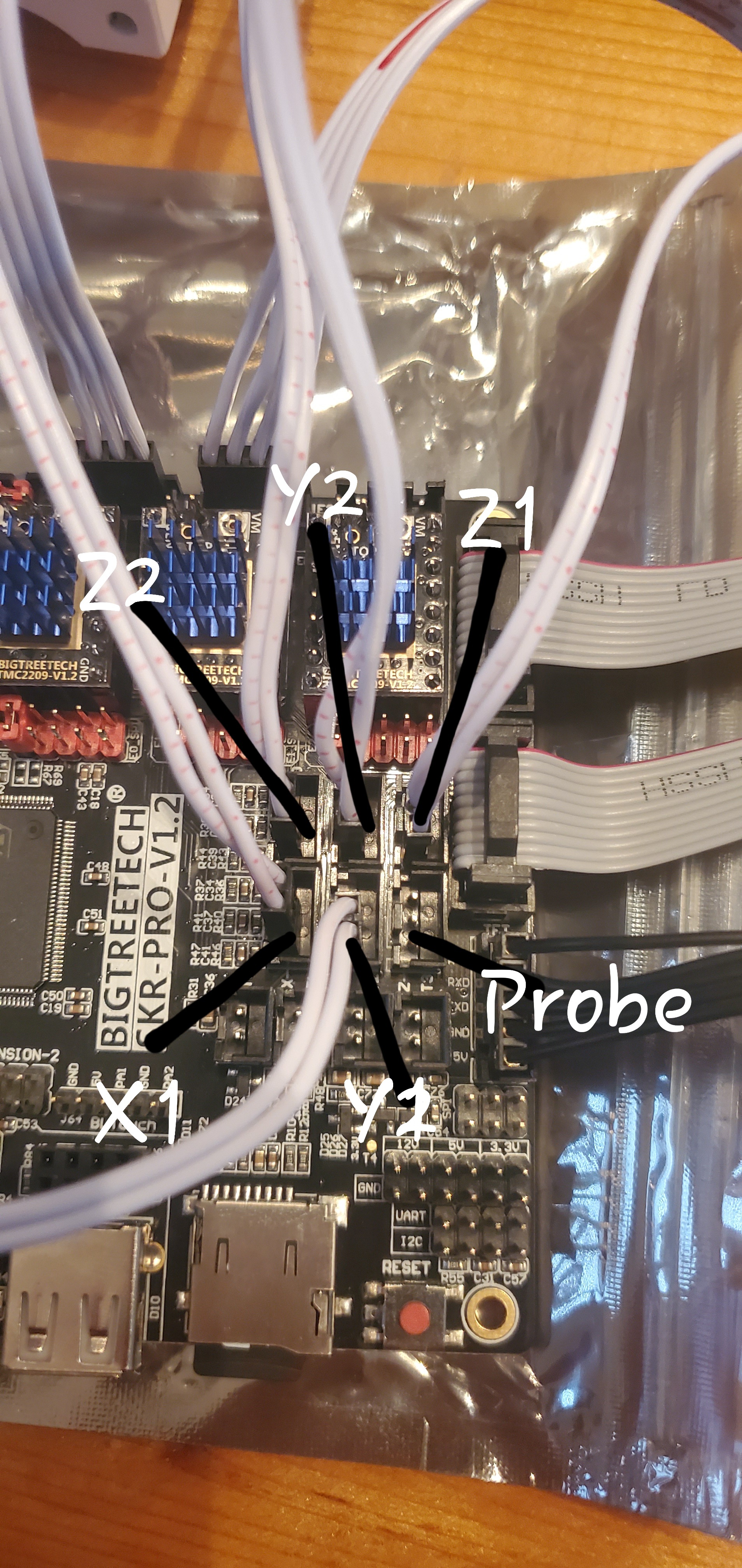
no end stops in place yet. I need to check the wiring is correct and all axis move in the correct direction and the Y axis wheels are running straight and all is square.
That’s the one! I let the smoke out of my last (good) one mostly I think overloading it using the random orbital sander, so a 6 year warranty when running for long periods attached to a CNC machine seems like it might be worth having.