Alright, since I took the photos;
When I changed the file Doug kindly shared to make it 5 Y spars instead of 4 I failed at the basic observation of the fact that while there was indeed a spar up the middle the sides were not symmetrical, go back and look again in case you missed it like I did but there’s a slot missing on one side.
Since they’re already split up and out of the sheet there’s no point looking at the layout file. The solution I came up with was this. And I’ll caveat this by saying right now that no one should take this as advice on what to do, I am not a reliable source as this project has shown.
So I’m not saying this is a good idea, but it’s what I did.
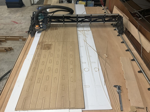
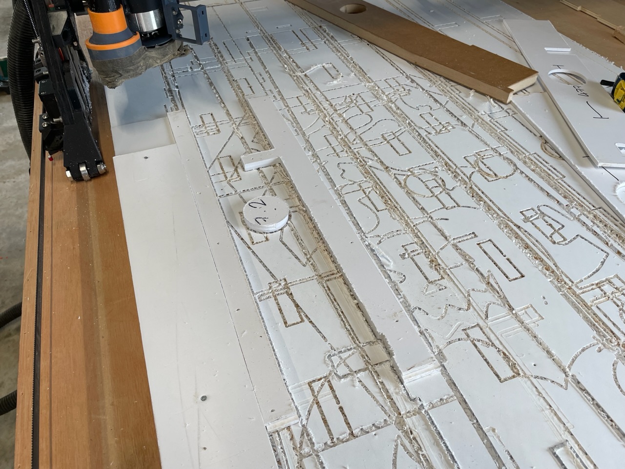
I took some of the foamcore I use as spoil and attached it to the bed.
Then I loaded up the corrected dxf in estlcam and at the end that needed the extra slot made a partial ‘part’ toolpath. Included in the geometry of this was one of the slots and the round cutout.
When this is cut out of the foam it makes a jig to hold the x ribs.
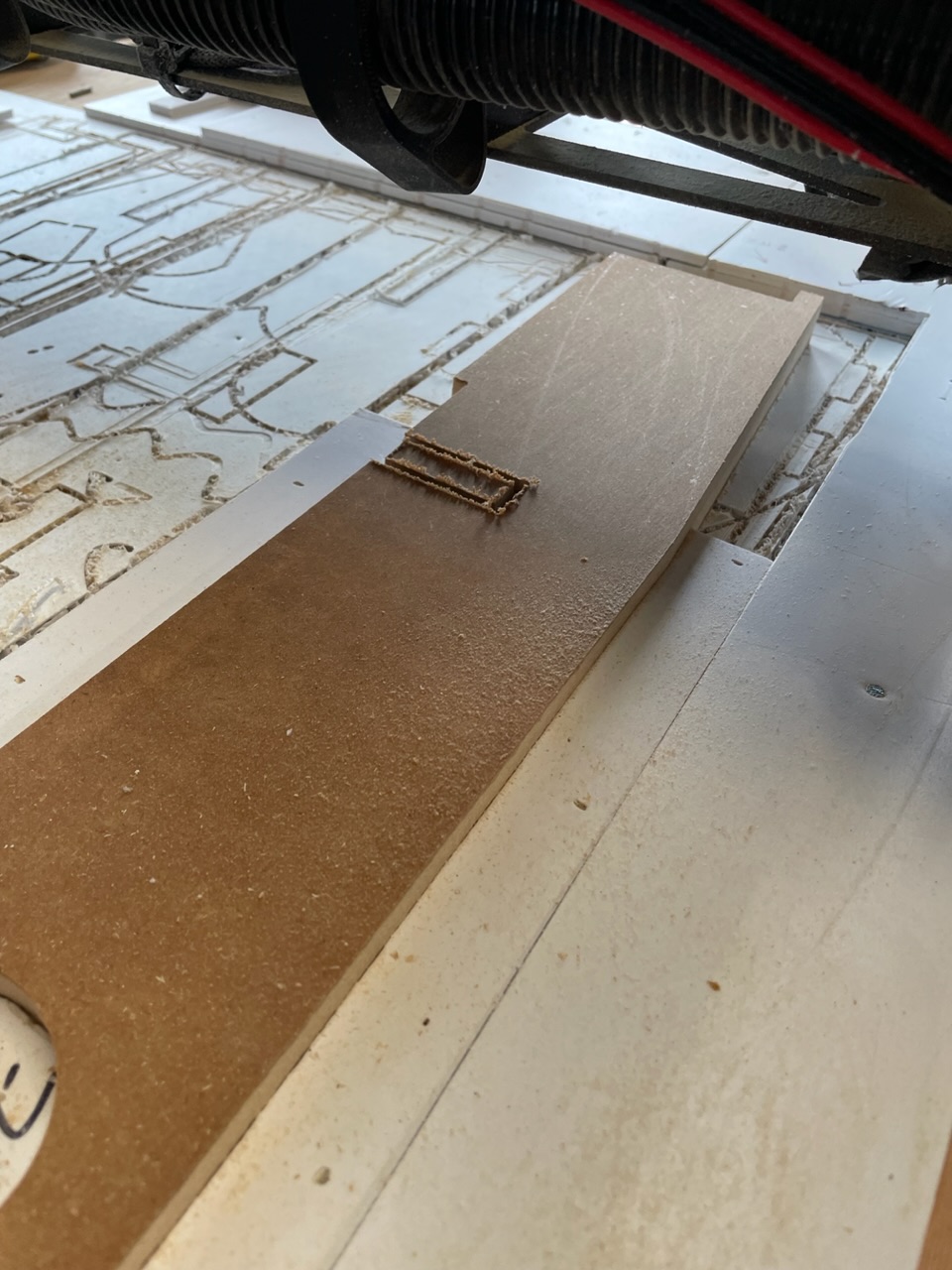
Now using the same dxf in estlcam the jig toolpath is removed the another is created that is only the slot that needs removed.
This should be a hole or engrave on the inside of the slot. If you leave it as ‘part’ the slot will be oversized. Guess how I know.
When it came to the 2 end pieces that don’t have the hole I removed that part of the jig.
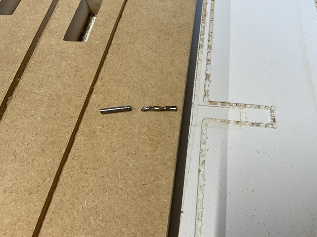
You can see in that last picture the difference between a cheap spiral cut bit and the 2 flute down cut bit Ryan sells. Which I no longer have… in one piece.
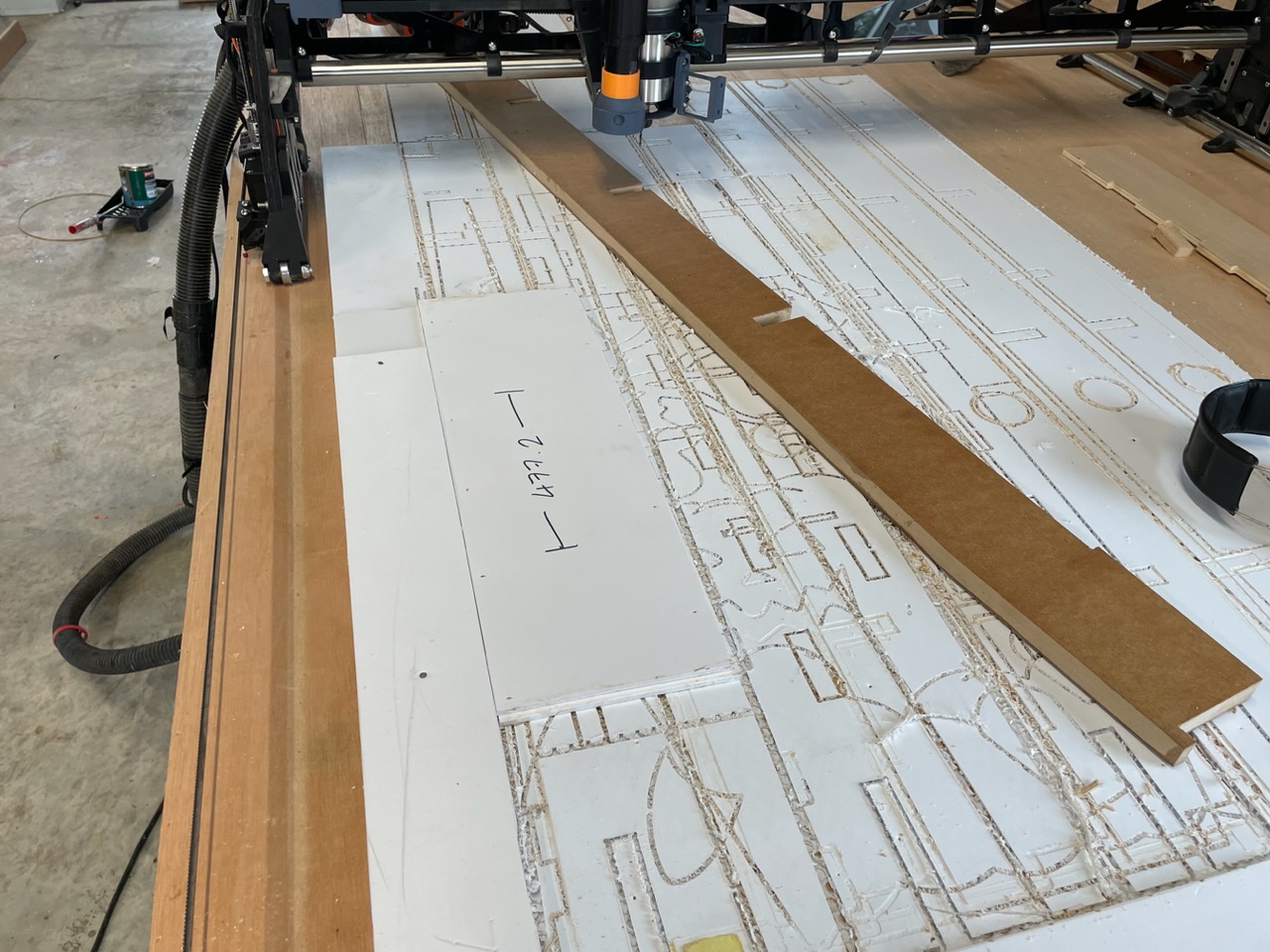
So that bodge kind of worked okay. The finish wasn’t great and I had to clean up both sides but it seemed to be workable.
That’s where the good news ends I’m afraid. You’ll notice there’s no mating half of the legs. Despite doing a full scratch pass first to check for clearances I left it running to get the kids dressed and when I came back one side of the gantry must have got caught or a cable snagged because it had wandered off course and destroyed the remaining half of the sheet. Foolish of me to leave it, it wasn’t for long but long enough.
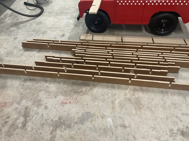
To cap it off, literally, I tried dry fit of the 5 ribs. I’m guessing the roller coat of polyeurathne either added friction, or even swelling as it was absorbed, or maybe I was putting too much torsional load on them but in any event when I tried to dry fit the pieces cracked and split, both as I tried to slot them together and while taking them apart.
Which is to say I’m throwing in the towel on this one. I’ve made more expensive mistakes than 2 sheets of MDF and a cutting bit but the mounting debit of errors means completing this is beyond me. It’s not fun butting against the limit of your capabilities but it is what it is. I would have liked to finish with something for the gallery but not today.
I’ll order a new Down cut bit and look at something less ambitious next time.