I have built a mpcnc with a skr 1.4 board and have a tft 35 v3 with dual endstops. i have watched hours and hours of video and heres where i am at. everything is done and plugged in but i cannot get the screen to display anything I have the firmware.bin file on a microSD in the skr 1.4 (this was pulled from the v1 github skrturbo dual 2209 software). I have put the tft35 software on a full sized sd card and have that in the tft35. The fuses are both saying 12v on both sides with a multimeter and i see a small spark/draw when the wire connects. I have flipped the black wire(tft) many times and tried with the reset wire plugged in I posted this on the facebook group with pictures and tried their troubleshooting yet no fix I am starting to believe i have a bad board but this is also with no knowledge or previous marlin experience.

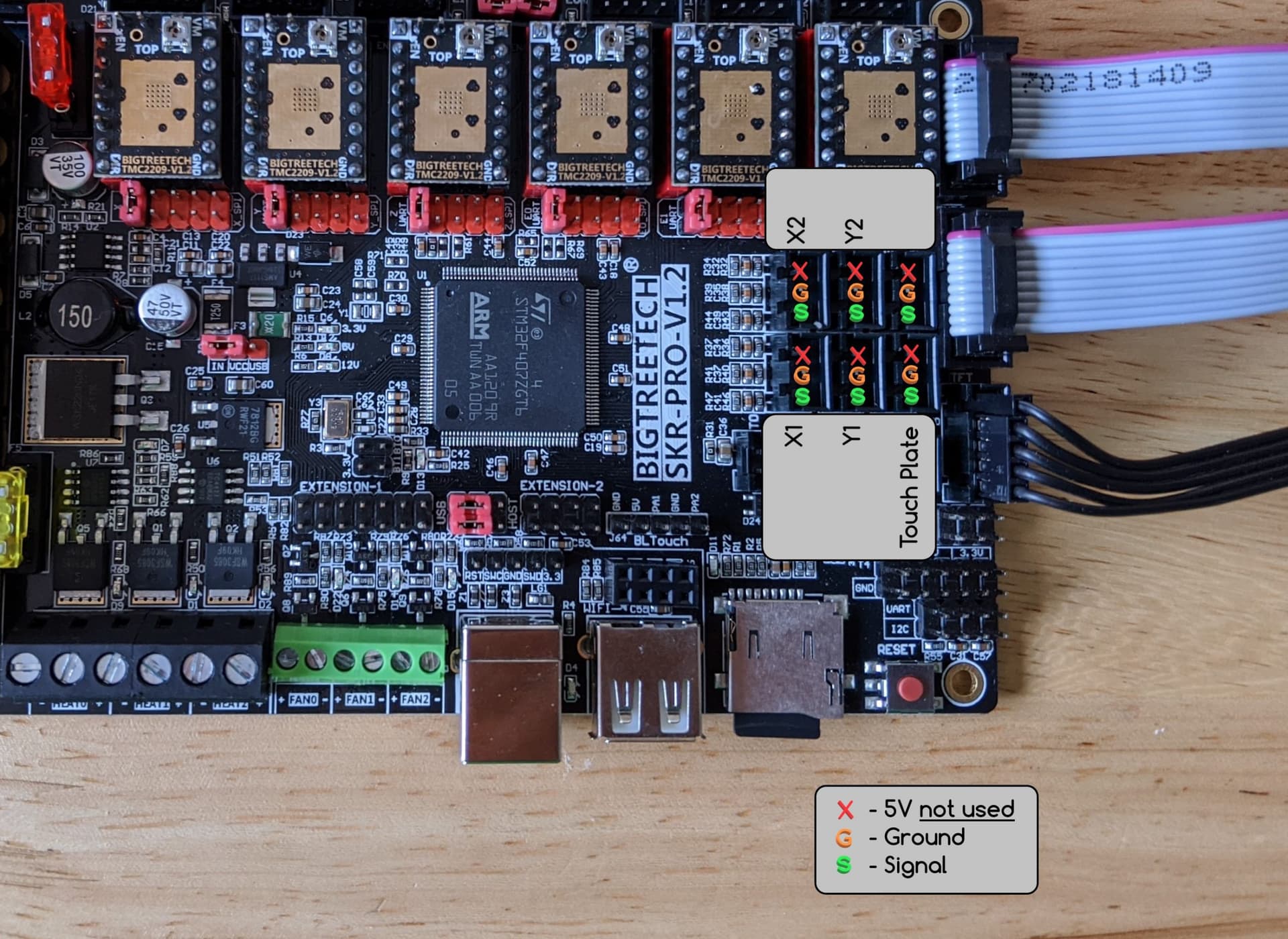
Your picture does not allow us to verify your wiring. Take a look at this picture. Verify that your 5V line in the five-pin (black) ribbon is correctly connected at both ends.
Verify that you have the USB/VDD jumper set correctly for powering your board from your 12V power supply (yellow square):

The board has a set of LEDs showing 12.0V/24.0V power, 5.0V power, and 3.3V power (blue square). Check to make sure all three are lit when 12V/24V is applied to the board.
The gray cables are used for Marlin mode, where the display is “painted” by Marlin. If you hold the display knob down for a few seconds, you enter Marlin mode. See if Marlin mode is working even if TFT mode is not.
Hi Robert I do have that jumper set correctly and I am not recieving any lights on the board when 12v is applied neither am I getting any lights when I move the jumper to usb when I plug into a laptop. The laptop only reads the board if I remove the jumper completely
I apologize. Your original post said SKR V1.4, and my mind with the SKR Pro V1.2 since it is the board that historically was used a lot with MPCNC builds. The picture above is for the SKR Pro V1.2. When I went searching for indicator lights for the SKR V1.4, all I found was this image:
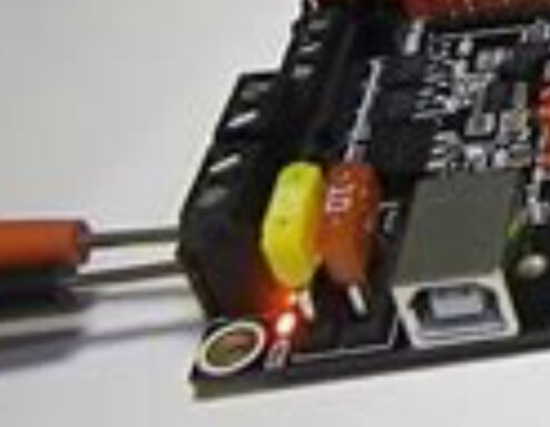
It appears the indicator lights are right next to the power-in terminal.
If the indicator lights are not showing, and if you have power on both sides of the fuses, then I would suspect a blown voltage regulator. This would be consistent with USB power driving the board, but no power when 12V is applied.
If you take a look at the pinout diagram for an SKR V1.4, there are a variety of places you can check to see if you are getting 5.0V output, including the pins for your display.
There are also some pins with 3.3V, and looking at the schematic, there is a separate voltage regulator for 3.3V. I suggest you test some 3.3V pins. If you have 3.3V but not 5.0V, then that would be strong evidence for a blown voltage regulator.
Thanks for all of the help I ended up figuring out that it was the end stops shutting down the board so I need to figure out why it’s doing that (1 plugged in makes the light dim and 2 or more plugged in shuts off the light) I also am not getting any movement with x2 and y2 so wiring or my driver jumpers are definitely the problem
You don’t have the 5v lines to the endstops connected do you?
You can see in my photo where they are connected
Xstop ystop e0det e1det
That picture does not tell me what wires you have connected to your endstops which is what I was asking. Only signal and ground should be connected, not 5v.
So just cut the 5v wire? It’s the same connection on both ends
https://docs.v1e.com/electronics/skrpro/#mpcnc-dual-endstops
Note
Do not use the + (positive) pins or you will ruin your SKR Pro board. Unless you are running a different project with powered endstops.
I have a skr 1.4 turbo board but i have cut the 5v wires and they appear to be working (light up when pressed) (board lights functioning properly as well.
I cannot get the x2 and y2 to move these are connected in the e0 and e1 slot. X1,Y1,and Z are moving just fine not quite sure why I also am not able to enter marlin mode either