MPCNC Primo - Italy

Hi All, I’ll keep track here of my new build of a MPCNC Primo, it’s my first cnc so it’s fitting as primo translates to first in italian :grinning_face_with_smiling_eyes:

I’m using stainless steel tubing 25mm od 2mm thick.

Work area will be about 610mm x 410mm. Lowest height as recommended.

All stainless steel metric hardware.

Printed everything on a bambulab A1 mini using 2kg of Sunlu PLA+ (white was the cheapest).

I’m waiting on the last missing piece to arrive (idlers) and a trip to the hardware store for some MDF for the base.

In the meantime here are the mostly assembled feet, trucks and core.

So far so good, the trucks roll nicely and the rail fit the core with everything rolling.

I’ve also tested my jackpot3 board after installing fluidnc and config, connected the motors and everything seems to be working.

Cheers

3 Likes

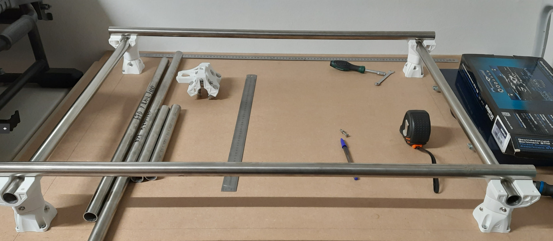
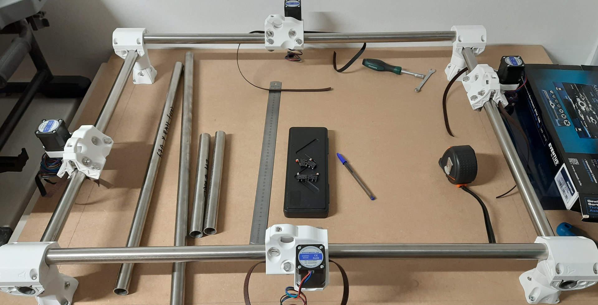
Quick update. Cut the mdf and setup the legs. Mistakes were made and I screwed them in 10mm less than initially intended in the Y direction but I got diagonals well within 1mm so I kept it.

Proceeded onto leg lock and corner bottom and ended up wasting 3 out of 4 leg locks. I did prethread the nylocks but the hole for them was way too large. Did superglue them in but probably glue got on the threads as well and they ended up spinning/coming out as it was super hard to tighen the bolts.

I’ll try to reprint with hole compensation…I’d rather hammer them in then glue.

Edit: I was able to recover 2 corner bottom but 1 was sacrificed in an attempt to separate it from it’s leg lock :neutral_face:

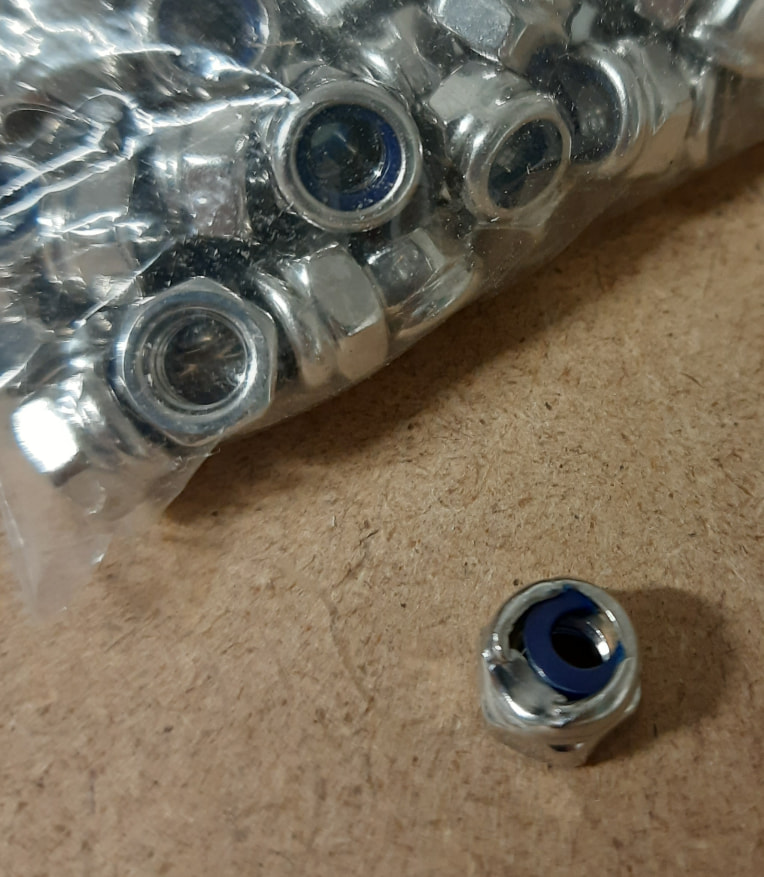
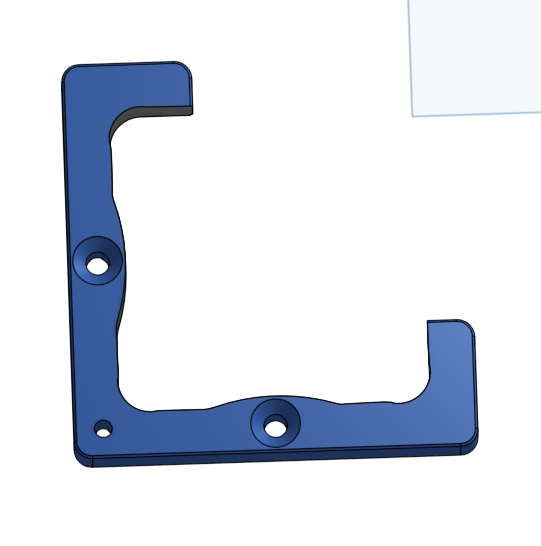
The reprinted leg lock wasn’t even close to being tight enough, ended up glueing again. This time different strategy: threaded in the bolt all the way, put carefully glue around the nut then removed the bolt and sprayed in the accelerator (it’s C8 glue). The result seems much better. I’m also considering the possibility these nylock are just trash, I started noticing they bind when threading the first time and they ruin my bolts. I also found this:

1 Like

Put some more hours in. Wasted an other leg lock :face_with_symbols_on_mouth:

While reprinting I cut all the rails. Finally was able to finish the legs and test fit the x/y rails.

The Y rails are all level within 0.15mm apparently.

The camera does a number on the X rails, they are reasonably straight.

Yes, that’s a tap kit, I’ve resorted to use a medium cutter for the m5 nylocks which doesn’t render them useless, unlike the finishing cutter.

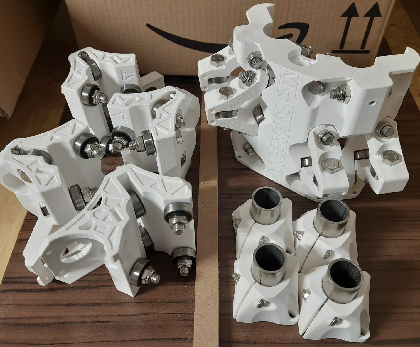
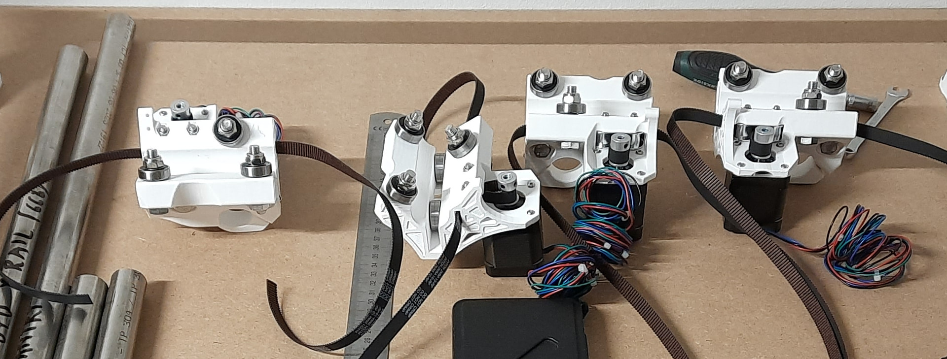
Given the idlers also arrived, I went on to finish the trucks. For now it seems there was no drama regarding these. Idlers and pulley all aligned and moving smoothly. I’m using a nylon covered belt.

And then at the last minute decided to press on and mount the leg tops too.

Of course once all said and done I noticed the trucks are on the opposite rails :sweat_smile:

Sadly I can’t just turn around the mdf board as there is no clearance on this side for the motor and would rub the wall.

1 Like

Some more progress today

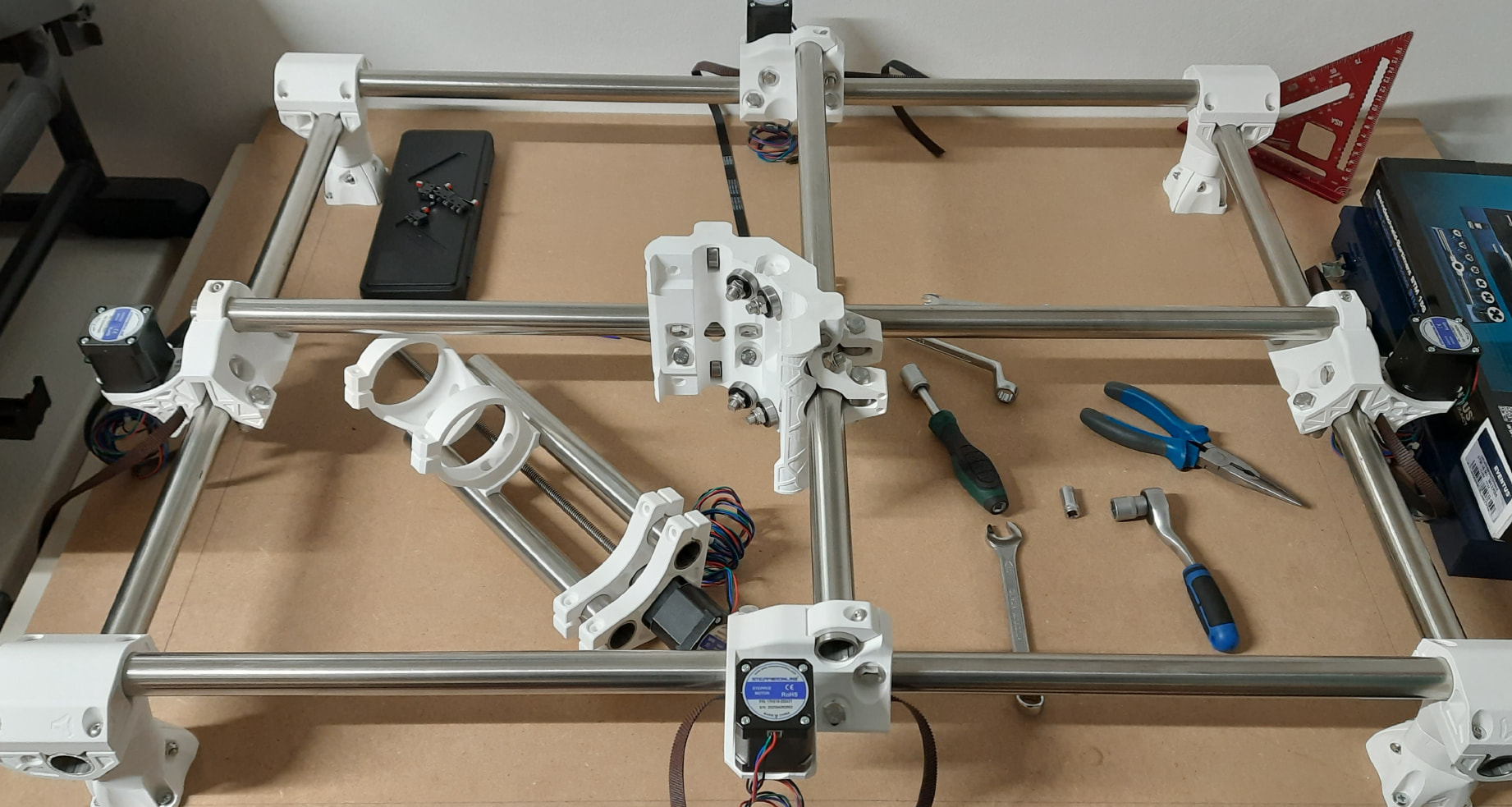
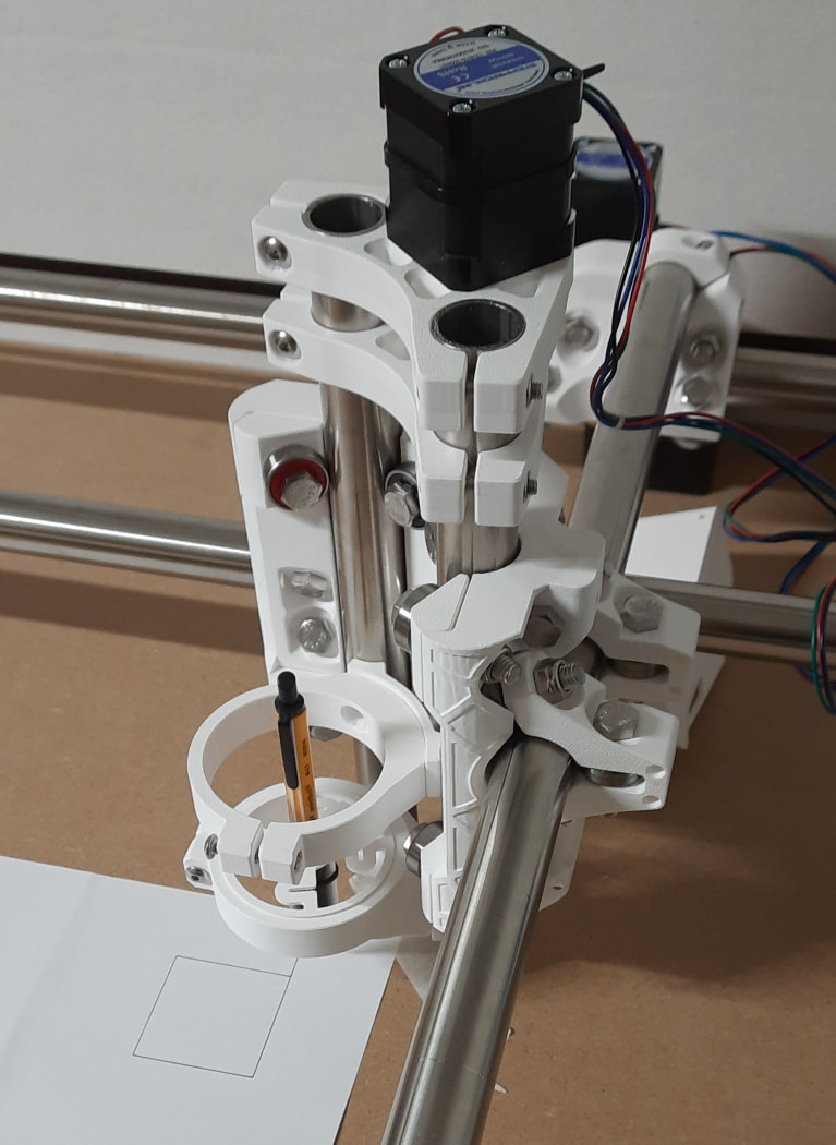
Fixed yesterday’s mistake and swapped around the trucks. Mounted the gantry rails, squared the trucks and added the core. It’s still a bit loose as I went on to assemble the z axis, everything was going smoothly and it finally came the time where the M8x40 bolts (as recommended), that seemed too long, became a problem.

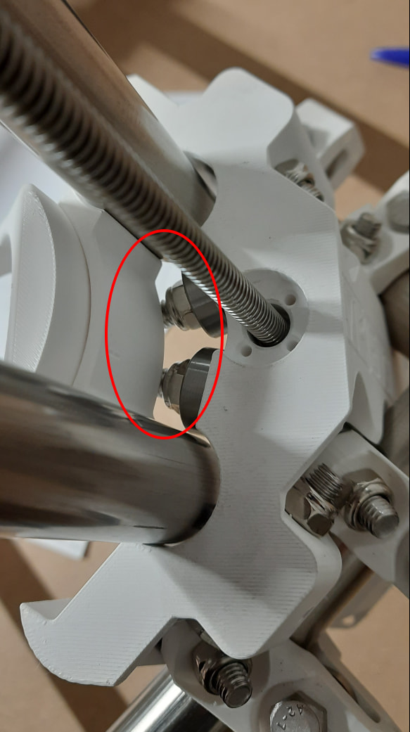
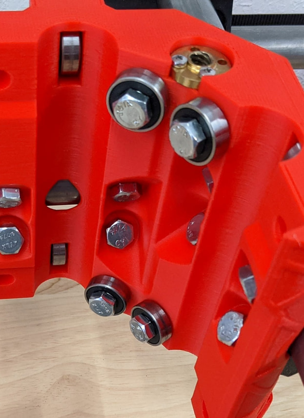
The tool mount is hitting the 4 bolts from the core:

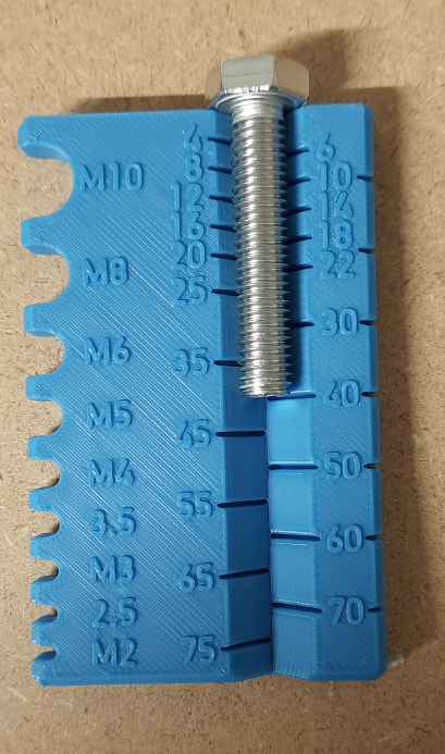
It was also cumbersome to hold the a couple nylocks when squaring the trucks, so, to me, it seems M8x35mm would be the correct size for the hardware. Unless 40mm is meant to be the full bolt’s lenght. Not sure how it works in freedom land, but in metric the bolt length excludes the head. So an M8x40 is actually 45.3mm long overall (40+5.3 head):

Anyway so far it seems everything else clears, it’s just difficult/not possible to put a wrench in some cases.

Hopefully my band saw won’t dislike cutting a few of those for the core.

I 3d printed a split version of this tr8 nut which works well while I’m waiting for a new leadscrew+nut+coupler to arrive.

I’m also missing 3 more bearings so I’ll probably just finish the belts.

edit: the lower part of the tool mount is on upside down, didn’t have a reference photo handy and got it wrong, of course.

edit2: ok I realized the bolts on the core are backward :man_facepalming:, easy fix

2 Likes

Quick update.

Attached Z clamps to the core. Fixed the direction of the bolts and slid in Z axis for a test fit. The toolholder too.

Added the endstop blocks.

I tried squaring up the gantry but was having little results. I rechecked the legs and they are spot on, I’m confident the base is solid. I’ll wait for the proper leadscrew and continue then.

2 Likes

Short update

Got and mounted the proper leadscrew, nut and coupler.

Connected all belts even if the machine is not squared yet as I’m planning to finish the base as a torsion box which means I’ll have to detach it.

Designed this small part to try and locate the exact current position of the feet. Will update if it works.

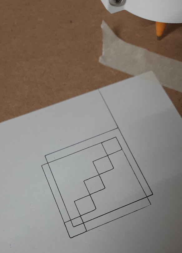
For now connected the controller for a quick test. Drew manually from the fluidnc interface a 50x50mm square, dimensions were spot on, diagonals 0.5-1mm off.

Second test another 50x50 square offset by 5x5 and then 10x10 smaller quares

Now I’m printing a drag chain for X and Y and waiting on cables and dupont connectors to finish the motors and endstop lines.

3 Likes