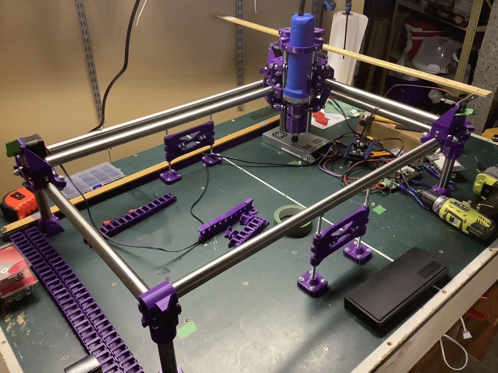
Started an MPCNC as a Covid project, it has sat on the side a little, picking it up again now and then. It’s a roller now, will put up a photo or two later, but a question as I plan the limit switches and drag chains.
Standard practice in the CNC world seems to put the home location back right for the machine, which allows the piece being cut to be loaded easily front and left. The gcode is then “zero-ed” on the front left of the part and runs in machine negative x, negative y space all the time. I understand that this is just like Z axis concept where the part top surface is “zero-ed” and we cut down and into negative Z.
Standard practice also seems to home Z where the axis moves to it’s highest. This allows for bit changes easier.
So, planning my limit switch locations for min x, min y, in the back right, and a min z at the upper location.
Is this MPCNC practice as well? Thoughts on this? Or will I be creating a lot of problems having my homing switches back right and top of Z axis?
Commercial mills usually have limited access to the bed, so they want to leave things out of the way. I’m OK with leaving things there, and putting the work in or taking it out from the side. There’s also the fact that many of those commercial mills can move pretty quickly to the 0, 0 positions, and the MPCNC is relatively slow that way.
If you use the limit switch provisions on the printed parts, then your home position is going to be 0,0 (Although I suppose you could reverse the directions for both X and Y with the firmware so that the machine is turned 180°. It’s not like it makes that much difference how the router is mounted to the operation of the machine.)
The Primo typically does not have a Z limit switch. The homing is done using the touch probe, to the work surface at 0, so it’s not a “home” position per se.
Actually, “home” is kind of a misnomer for the MPCNC. The endstops are more for squaring the machine than homing it, as we tend to home the machine to the work. Most of us do not use work coordinates, and several don’t even have limit switches on the machine at all, so “home” is wherever the machine is when it’s powered on. We move to the near left of the workpiece, and tell the machine “that’s where your 0, 0 is.”
The (community supported) firmware for the LowRider homes Z to the top, and uses a touch probe to zero Z to the work, but again, it’s probably better to think of those switches as squaring rather than homing.
Interesting, and thanks. I installed some X rail supports as we hope to dabble in some aluminum plate one day, so can’t put material in from the X or long side. Have to go in from Y or short side, or down from the top.
But, another question comes to mind. Using limit switches to square the machine, does the squareness wander as it moves to the other extreme? In other words, is it better to be cutting nearest to the point the auto square is achieved?
I’ve not seen the structure between the rail supports before. Square should be the same across the whole cutting area. Some folks have issues getting the frame perfectly square. The dual endstop firmware helps with this by homing both ends separately and allowing them to be adjusted independently.
All the 3d printing was done last March and April. We assembled it early Aug after re-purposing a portion of ping pong table… As we were assembling, we went looking for those mid span supports and I could not find them. It’s really two threaded rod supporting the X axis from below to eliminate sag, if any, but I figured it might add some stiffness against sway too.