MPCNC from Paris

Hi everyone,

Firstly a bit of introduction,

I saw the MPCNC in a friend place in Shanghai in 2016. At that time i don’t have need of it but always kept in mind because it is an amazing machine !

I currently owned two 3d printer (Tevo little Monster with Duet3d) and having some fun and fails to print MPCNC parts use spare parts from an old delta from BQ with a very bad frame.

MPCNC Info and soon photos : 12x24’ and around 4-5’ Z height.

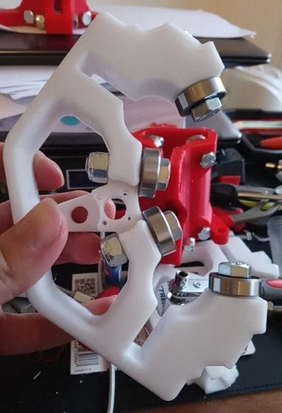
25mm version with V1 bundle series kit.

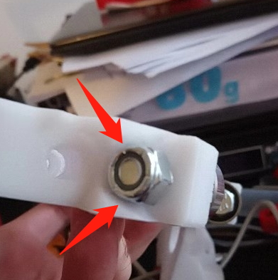
The machine is dead square (i have a little play on the middle assembly (around 2-3mm) and approximately 1mm accuracy on Y axes.

3d print was ok (i cracked some parts - print too fast / bonding issue). (By the way don’t print in PETG the middle assembly - very bad idea)


Now everything is plugged and square but i have some ISSUES…

  • Rambo board v1.3
- if i plug the endstops then i don't have the green light on the board anymore when powered
  • if i run without endstop i have a little move on Z (seems underpower) but no sign of life on X-X1-Y-Y1

i did the bridge on logic. I try with 12v6ah and 12v30ah power supply. Same result. Nothing moving
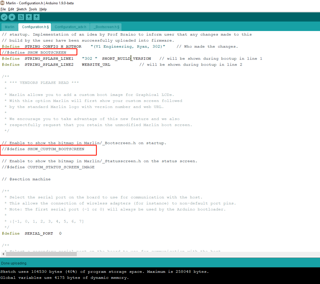
  • Marlin
-i followed 'info page' tutorial so far so good with 'upload done!' but I can't get the reprap discount smart controller working. (lighting but i get white squares on display)

Any tips on config files? (Arduino V1.9.0 beta - U8 and preferences set / Rambo set)


Finally : Uploading marlin

-running my old ramp v1.4 i can get it moving. so my wiring seems correct.


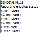
I chose to go on auto square with endstop so i am plugged in series.

Really don’t know what is the deal here. Any tips please share with me.


Use my firmware and that is not how it is done. Have a look at the endstop section.

https://www.v1engineering.com/auto-square-dual-endstops/

Hi Ryan,

Thank you for your quick reply. I found out my mistake between X1 and Y1 endstop.

Now i have the Green light !!

I successfully loaded Marlin-1.1.x. Maybe the photo bellow will helped.

Running pronterface. I can connect but no sign of life…

M119 show XYZ triggered (i have no endstops on Z)


Here a photo of the wiring

[attachment file=79630]

Also a photo of the MPCNC

[attachment file=79631]

Why not use my firmware?

Hi Ryan,

I got lost in Github. First time ever i go there. Don’t understand anything on this website…


So two things and some goods news :

  • Running version without endstop everything is working ! X Y Z. All smooth.
  • Running version with endstop : XYZ opened but at the end i have this message :
Error:Printer halted. kill() called! [ERROR] Error:Printer halted. kill() called!

I suspect a signal problem on one endstop. not sure why… it’s 1.30am so i am going to stop there for tonight.

Also i still don’t know how to use my old reprap smart controller on this rambo.

Hopefully everything will work before Xmas =)


Hi Bro,

I don’t know anything about the RamBo since I only use the Arduino/ramps, like a caveman, so I m not really sure I can help on implementing the reprap screen,

However, if you want to download Ryan’s firmware, just go there:

Then click on the grey button on the left named “Branch 1.1.x”, then select whatever firmware you want in there. After that, click on the green button on the right named “Clone or Download”, select zip and it should start downloading.

After that, open the Arduino IDE, install the U8glib library and all the other stuff, then go to the “configuration.h” tab.

Scroll down to line number 1731. You should see this:

#define REPRAP_DISCOUNT_FULL_GRAPHIC_SMART_CONTROLLER

Change it to this:

//#define REPRAP_DISCOUNT_FULL_GRAPHIC_SMART_CONTROLLER

Then scroll up to the line number 1601.

Change this:

//#define REPRAP_DISCOUNT_SMART_CONTROLLER

To this:

#define REPRAP_DISCOUNT_SMART_CONTROLLER

I’m not sure if the MPCNC can work fine with this screen, maybe Ryan can tell you, I’ve only used the bigger ones with this machine, but that’s how I did it for my other 3D printers.

Hopefully it should work fine after that. If it still doesn’t then check the two following things:

-First, try fiddling with the screen potentiometer to adjust the contrast. It happened to me a lot of times that the potentiometer was wrongly setup from the factory, either at maximum or minimum contrast, so even if everything is setup properly you still can’t see shit. That’s super annoying, whoever produces those boards suck.

-Second, try plugging the cables in any possible way, for instance last week I discovered that the brand new screens I purchased were wired wrong, the connectors were soldered backwards… I had to cut slots in the plastic connectors to fit the cable in the right orientation. Actually I had both problems (contrast and backwards plugs) so it took me about an hour and a half to figure out WTF was happening…

Good luck!

1 Like

Some updates :

Now i got the endstops working. Funnily i didn’t change my way to upload my boards. I believe i just caught the bad files from very beginning instead of Ryan version.

I am not a huge fan of Marlin. (i went into it 2 years ago. Catching back)

here my M119 command :

[attachment file=79693]
Now the screen : Dui style =)))

Second, try plugging the cables in any possible way, for instance last week I discovered that the brand new screens I purchased were wired wrong.

Funny, it is the same case for me. So far it’s the best result i got playing with ext1 and ext2.

[attachment file=79692]

Now i trieds your trick :

#define REPRAP_DISCOUNT_FULL_GRAPHIC_SMART_CONTROLLER

Change it to this:

//#define REPRAP_DISCOUNT_FULL_GRAPHIC_SMART_CONTROLLER

Then

//#define REPRAP_DISCOUNT_SMART_CONTROLLER

To this:

#define REPRAP_DISCOUNT_SMART_CONTROLLER

If i do that. Arduino say Fail to load Rambo Board. any ideas? it’s simple coding. why it’s not working?

M119.png

[attachment file=79696]

I am surprised by this. I was of the belief PETG has very good layer bonding. Do you think it was just your settings? I have printed all my parts using PETG at present and they look pretty strong. I am waiting on delivery of the kit from Ryan before assembling so have no proof yet that all is good with my PETG parts but they feel strong.

Trev

Well to be honest it is strong. But is also very flexible. I also found some people successfull with PETG on the forum.

[attachment file=79723]

I was trying to mix PLA and PETG to get a bit flex on the Z axis to impriove the first bit. But i ended with my central XY assembly not perpendicular. I redo some print in PLA and all went well. (i didn’t want to force the assembly with belt strength)

[attachment file=“first shot with PETG.jpg”]

The second minor problem you will get it is two screw sides bearing on burly XYZ. The bolt will not be locked in it.

[attachment file=79721]
[attachment file=79722]

On my printer you can see 3 colors :

  • White : PETG 0.3mm layer height
  • Red : PLA 0.1618mm height : Printed at 65mm/s - bad bonding - too fast
  • Orange : PLA 0.3mm height : Printed a 45mm/s - 3 walls - very strong
It was a first build. Dui gave me some tips and told me to go overall the standard design of Ryan before to run improvements.

It’s way too early to talk about it as i have no experience yet with this machine.

Meanwhile you will have a fun assembly.

Burlypetg.png

All my petg parts are 4 perimeter 50 or 60% infill.

Ok, I just tried on my computer, the issue seems to be because the custom welcome screen is enabled.

So you just have to go to line number 92 and change from this:

// Enable to show the bitmap in Marlin/_Bootscreen.h on startup.
#define SHOW_CUSTOM_BOOTSCREEN

// Enable to show the bitmap in Marlin/_Statusscreen.h on the status screen.
#define CUSTOM_STATUS_SCREEN_IMAGE

To this:

// Enable to show the bitmap in Marlin/_Bootscreen.h on startup.
//#define SHOW_CUSTOM_BOOTSCREEN

// Enable to show the bitmap in Marlin/_Statusscreen.h on the status screen.
//#define CUSTOM_STATUS_SCREEN_IMAGE

Basically make sure those two options are disabled. Marlin tried to load and display the vicious1 logo at startup on your screen, but the screen is just too small to display it so that cannot work!

It should compile fine after that. At least it worked fine for me. :slight_smile:

Next time, pro tip: the errors are displayed in orange at the bottom of the Arduino IDE. You can scroll up to see the full error report or enlarge the error message zone by dragging up the separator, then try to read what this is telling you. Then , copy the parameter it’s telling you causes problems, and use the Edit–>find function to directly see where it is in your code. Not sure if my explanation is very clear, but don’t be afraid to use this thing, Marlin is actually very easy to edit and work with once you get it.

I checked my report. Indeed it was a bootscreen error. Problem solved in 5 minutes after reading your message.

So i just disable it and now it works smoothly. I think i am going to add an extra endstop for Z.

Some screen shot for those who need it.

[attachment file=“Bootscreen3.jpg”]
[attachment file=“Bootscreen2.png”]
[attachment file=“bootscreen.png”]


[attachment file=“Bootscreen3.jpg”]
[attachment file=“Bootscreen2.png”]
[attachment file=“bootscreen.png”]
All working well after your advice.

Hurray!

Time to make this thing dirty now!

1 Like

Final result.

[attachment file=79985]
I bought a cheap box to put everything in quickly the time to mill some nice parts for it.

[attachment file=“79986”]

and a logo just to make sure everything work smoothly.

[attachment file=79987]

Now back to the main talk on this forum. What tools???

C02 laser is out of my budget.

Plasma is too crazy. I leave it to you Dui =)

Dewalt DW660 is cheap but unfortunately not available in France.

I checked amazon and other website for a month or so.

It’s much more expensive running 220v here in europe and adding a converter is not a good solution.

Kress is good but i am not going to use it crazy so i don’t think i have to go so high quality.

A spindle? ok for aluminium but if i want to mill beech wood and high density wood / 22mm MDF???

Any ideas are welcome.

2 Likes

Is it me or sometimes the forum crash ? I have troubles to upload photos.

They have to be under 6mb. We are eating up server space like there is no tomorrow even at that size.

i usually compress before to upload. There is already enough MPCNC with nice photos.

Kindly let me know the offset between XY pipes. i have slight play on the middle assembly. I wonder if it’s my print parts (bonding issue) or if i didn’t tight enough.

I am dead square using a pen but milling could be another story.

27.5mm

1 Like