MP3DP V4 build PLOG

A carbide toothed blade on your table saw works fine. I usually use a 7¼" blade for it’s narrower kerf plus it’s not such a loss when you chip or lose a tooth. A blade lube stick makes things easier and safer.

I wouldn’t worry about the aluminum. It cuts a lot like wood on a chop saw/table saw. There are blades made for cutting Al, but if you only need a couple, IDK if it is worth it. Just don’t cut it too fast. I personally would use the chop saw and cut the 4x at the same time to get them the same length. Mostly because I don’t want Al chips on the table saw.

1 Like

Okay, that was kind of annoying. Somehow I managed to cut the 3 pieces 420mm and 3 pieces 355mm 3mm short, so I botched that. I re-cut the 417mm pieces to 355, but the 352mm ones are unusable. Fortunately I had 10 pieces. I should have had 3 1m sticks left over, but now I have 3 that are 572mm ish Not sure how I got the 3mm short, I think that I didn’t re-check the measurement after clamping down the fence.

Took some time to sweep up all the man-glitter.

We now pause for a break to deal with a dire emergency. I have apparently depleted my entire store of cola, and therefore have no caffeine supply. This is probably more dangerous for the people around me than for me per se, but I need to rectify the situation immediately.

1 Like

Did you cut on the wrong side of the line? Most blades are about 3mm wide.

Starting construction… there is no guide yet, so I am going to make some educated guesses as to an order to put things in from the printed pieces and pictures of Ryan’s build, as well as the CAD render.

Note my extrusions and rails are all 50mm longer than listed.


Okay, so I have:

  • 4x 345mm frame upright pieces
  • 4x 345mm frame Y axis pieces
  • 3x 370mm frame X axis pieces
  • 3x 305mm Z axis upright rails
  1. I’m going to start by sliding in 3mm insert nuts for the primted pieces and MGN12H rails. If I start with the Z axis rails, each belt holder needs 1 3mm nut, and the rail itself needs some. I will use 4, similar to how I did for my Repeat, so 6x 3mm slide nuts. I also added right angle corners to each end using 5mm slide nuts. Parts used, 3x 305mm extrusion, 18x 3mm slide nut, 6x 5mm slide nut, 6x right angle corner. 6x Z belt holder 3x 250mm MGN12H linear rail.

  2. Next I prepared the frame uprights. These need the tension blocks on the front, each needing 2x 3mm screws. I assume by design, the holes on the tension blocks exactly match the slide nuts with the long ends pointing together. This makes for a nice neat appearance. I also added the corner brackets here. 4 facing to the side of the tension blocks, and the 2 bottom ones facing inwards. The rear uprights I only added 4 corner blocks to for now. There will be additional slide nuts for the board mount, but thise are exposed on the outside and can be put in later. Parts used, 4x 345mm extrusion, 2x tension blocks, 4x 3mm slide nuts, 14x corner brace.

3 Likes
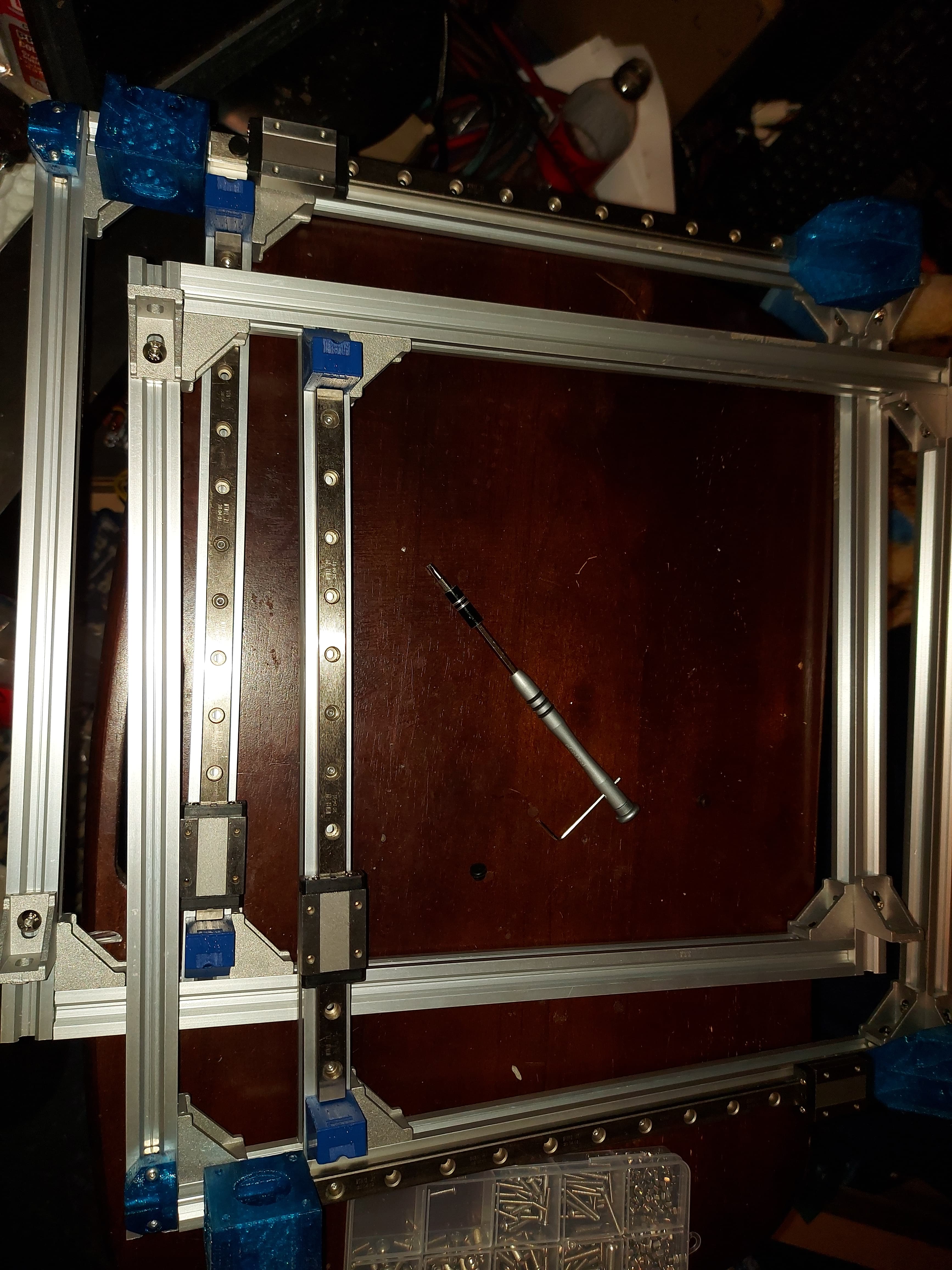
  1. Preparing the Y rails. I again chose 4 3mm screws each for the MGN12H rails. Each motor block needs 2 3mm screws, the right hand one has one on top instead of 2 side by side. The bottom rails only need the 5mm slide nuts to bolt to the upright rails and the Z axis extrusion. Parts used: 4x 345mm extrusion, 1x left motor mount, 1x right motor mount, 1x left back corner, 1x right back corner (hope I got them in the correct places) 2x 250mm MGN12H rails, 12x 5mm slide nuts.

  2. Assemble left and right frames. I found that it was easiest to install the Z axis uprights first, then the front and rear frame posts. Don’t tighten the Z posts too much, I needed to move them for access to the screws in the front frame upright. Even after getting everything assembled, leave most of the screws a little loose, except the screws that you need to move the Z posts for. Tighten the Z posts to be 50mm from the front uprights. This will serve as the reference to square the machine to when we adjust things.

3 Likes
  1. Adding the X axis frame. The only thing tricky here seems to be making sure you have the 3mm slide nuts in place for the corner pieces. Again, I found that installing the Z axis on the back first made things easier.

Note, the cat complicates assembly. Do not recommend, particularly when she likes to play with small parts and screws…

Assembly pauses here, since I am out of M3x10 screws.

5 Likes

I just spent a bit tightening and squaring the frame.

The Z axes don’t center on the uprights. They should tend towards where the bottom is. This is probably best done after you install, unless you’re really confident. When centered, The X and Y rail cars touch them, and it looks like the parts that hold the X rail will completely crash. Pushed down a couple of mm and it works, and I think the Z motor mounts still get close enough to the top.

I was a little worried that I should use corner braces on the bottom X extrusions, but it’s easy to get a square in there without. Makes it nice.

I might consider an extra set of braces for the back Z rail. Looks like not.possible for the front 2, though. I get a little movement on the back rail, maybe because of the V slot extrusion. Well a little torque will probably manage that once I’m sure that the rail is properly centered.

I have left no real provisions for mounting the control board. Since I’m not using the SKR Pro, I didn’t print those pieces, so if someone does some real documentation, should probably include that. At some point I see I stopped adding parts used, and I think I missed several mentions of the M3 slide nuts. :man_facepalming: well, it’s supposed to be a project log, not assembly docs, but I was halfways trying to do it instructions style. There is a good reason that I write code and not procedure manuals for work…

Now to order another bag of M3 screws.

2 Likes
  1. Install the X axis rail. You cannot install the rail to the XY blocks and install the assembly, but at this point, I found it useful to check the fit, so I uses 2 M3 screws, one on each end, just into the plastic. I then installed each XY block onto the Y axis rails. If you, like me, bought M3 screws with a 2mm hex pan head, this is going to be a royal pain, unless you have long, thin 2mm hex drivers. (I don’t. :man_facepalming:) Either get phillips head screws, or get a long 2mm driver, because the Z axis is even worse. (I’ll pick up a driver tomorrow, because I have 300 of those screws arriving Tuesday…) Anyway… install the left and right XY blocks to the rails, and the X carrier/core piece to the X rail. It’s slightly easier to do first, and then install the X axis rail to the blocks using 4 M3x10 screws and nuts. We haven’t entirely squared up the frame yet so there might still be a bit of wiggle in the top rails, allowing you to adjust them to the actual length. Mine were a snug fit, which was a relief.

I had planned to get the Z axis done tonight as well, which would complete the parts that I have printed, but as mentioned, I don’t have an appropriate screwdriver, so I will pick up one tomorrow. I think the Dollar store has a set of precision screwdrivers that are kind of crappy, but should last for the 12 screws or so that I will need them for. I keep buying the set and throwing it all away when the M2 and M2.5 drivers break. Maybe this time I’ll look for a better set.

I think this is the end of the printed parts assembly for what I have now.

I will need to print a Hemera hotend mount for it, install the endstops, and then I can cut the heated bed support. I also need to design a control board box, but I bet that someone will have designed a nice box to attach the Duet 6HC to 2020 extrusion already. If not, I’ll mill something that will do the job.

This printer will have no LCD. I had one briefly on my other Duet printer, but with the web control, I never used it. I use them on the CNC machines though.

3 Likes

Okay… Went to pick up long allen keys, got a multi-bit screwdriver with Allen key bits, but the bits are 1/4" drive, and they don’t fit in the Z trucks. :man_facepalming: looks like I need a better solution. I think there were some long regular hex keys…

Long, thin allen key screwdrivers purchased, and the Z axis mounts are on the rails, and I mounted all 5 motors.

For some reason, I have 4 motor pulleys. I’m quite sure that there are more, but 4 is what I can find.

I installed most of the idler pulleys, but 2 of the ones in the back corners won’t turn when they are in, they are binding against the back of the part. The prints look good, so not sure what’s up with that. I can probably file some material away easily enough, but that’s a little worrying. I can put the 5mm screws through, so they can’t be too far off.

I guess I need the hotend mount for the Hemera, and I need to decide how and where to mount the control board.

I will also need to cut the build platform mount. Guess I’d better confirm the mounting screw placement, too. It wouldn’t be good if I can’t mount the build platform.

I was expecting the optical stops, looks like back to the micro switches?

I got some park tools allen wrenches for a gift a long time ago and they are my favorite. They are meant for bikes, but they work well and come with a wall mount.

2 Likes

So another difference in the BOM between the Repeat and the V4… Smooth idlers. The Repeat uses 3 toothed idlers for the Z axis, whereas the V4 uses 6 smooth idlers for the Z axis.

Amazon was supposed to deliver another pack of 5 smooth idlers for me today, but they’re not here (And promised delivery was 15 minutes ago.) Yep. “Sorry it’s late” message. I am 3 short. I happen to have the microswitches for the axis, so that’s all good. I kind of want to put the Z max endstops in place too, particularly since I have the optical stops already.

So a bit of an.issue with the back 2 corners…


Just a little too tight. I can get the 5mm screw through, but can’t turn the pulleys once I do… well, I could if I forced it, using a piece of GT2 belt.

Solution was to grab a small file and grind out the part where it rubbed. Good enough.

The lower rear belt is super close to top belt holder for Z3. I can’t move it down any further, and have not yet installed the Z belts.

I got the CoreXY belts installed though. And the XY axes are as square as I can measure for the span. Also mounted the endstop microswitches though they don’t yet have wiring attached.

Need a control board mount still and the build plate support. The LR3 is in a state of semi disassembly now, so can’t cut them immediately. Still, it’s starting to look like a printer.

My package of smooth pulleys arrived, but I’m still short one 16T GT2 motor pulley. Dumb thing to be missing. I’ve got to have spares somewhere, but darned if I can find 'em.

1 Like

Finally got my 16T pulley. What a nightmare…

So looking at the Z belts and not entirely sure how to tension them. I have the holders as far down as they can go, and with the top holders hard against the Z rails, it seems that they are tight to the Y trucks and the Core XY belts at the back of the machine, to the point where I don’t want to raise them. This doesn’t seem to leave a whole lot of leeway to adjust the belt tension. Have I missed something?


It’s beginning to look like a printer…

So of course I had the lower Z belt mounts in the wrong place, on the Z axis extrusions, instead of on the base extrusions. I rectified that and was able to install the Z belts and give them some tension.

I think the printer desperately needs some feet. It’s OK on the cardboard box, but even there I can see scratches on the surface. I don’t want to put that on my desk.

2 Likes

Feet are a big deal on this one. I did something like this in all 4 corners and put some rubber feet that I have for cutting boards on there. Works great to keep it from sliding, reduce vibration/sound, and protect the table. The back corner feet also help keep the machine square.

5 Likes

I just bought a spool of TPU which I want to use for feet. I have never attempted to print a flexible filament before, hopefully the Hemera lives up to its promise of good filament control and I don’t have excessive trouble.

/* sidetrack to project …

Meanwhile, I’ve been quite distracted with a retro arcade project. Two of them, really. One to replace the existing system, and one to be able to deal with alternate controls. I think that one will need a modular control panel. I still want regular arcade joysticks, but also want a trackball, which the old panel does not have room for. Then there is the GRS flight yoke that I got specifically for Star Wars arcade. I think I can manage with 2 panels, or maybe the flight yoke can be an add-on… I am starting to think of this one as a full sized cabinet, with a relatively large display. I want a 4 player cabinet, but can’t seem to draft up a cabinet less than 3’ wide. Maybe not a problem if I decide to use a 32" or 40" TV as a display.

Now returning to regularly scheduled PLOG */

1 Like

I tried TPU recently and had ZERO luck. I am not sure if it was the printer or me. History would point towards it being me. Let me know if you find success with the TPU, I’ll need to pick your brain on it…

2 Likes

I have a spool of TPU but have been too scared to try it LOL