MP3DP V4 build PLOG

:face_with_hand_over_mouth: There is no such thing as “Done”…

Maybe not! I was thinking about the moment where you feel that you are “satisfied” with what you have built.

1 Like

That is more unrealistic than done I guess. :smiley: I always added/changed something with Schneewittchen… :stuck_out_tongue:

Well, what I have are 12V white LEDs, so no colour changing, but I could ramp up the brightness with temperature…

At this point it’s all just wiring, the mechanical stuff is done. I have a history of rushing at this stage and just putting stuff together “for now” and Im trying to do this differently. Probably done this weekend though

3 Likes

https://www.printables.com/model/395108-drag-chain-mounts-for-mp3dpv4

I just published the drag chain mounts for this. There is a mirror image set if people want to put a chain mount on all 3 Z axes. It is likely possible to do without, though.

This assumes that the motor wires will come out below and towards the linear rails. Hopefully the clamp system never has to see a lot of stress. I want the wires to come out upwards, so I set it up that way.

I measured the center of the Z stepper to the center of the 2020 extrusion as exactly 59mm. There isn’t much leeway for the print to stay inside the perimeter of the extrusion, .5mm nominal.

The drag chain that I have is 14mm across the mating surfaces with a 6mm joint, and 5mm clearance around the joint, so the parts are designed for that. I think this osmpretty normal for 10mm X 10mm drag chain, of course of you print your own, it may be better to remix using your own end pieces.

3 Likes


The front panel was a royal pain. I think because the 2 front uprights didn’t want to sit quite as square as I would have liked, the slide nuts kept falling out of the track and dropping. Finally I slid the cross bar up as high as I could, under the tension blocks, and put the rest of the slide nuts onto the front piece, and slid it back down into place. Sure enough the top was about 1mm “pinched” in at the top. Now it is not.

If any of the previous panels had given me this much trouble I’d have given up with only the back (which I did first.)

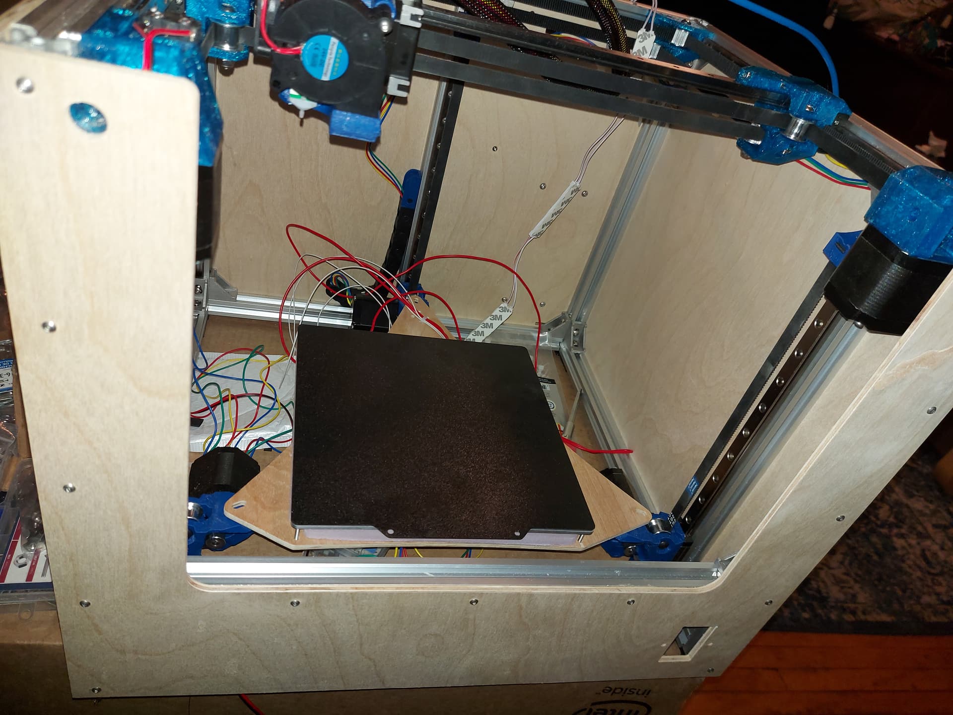
The panel features a 65mm cover on each side, mostly so that it can provide reinforcement to keep the pillars parallel. Also a 12.5mm hole in front of each tension block (I measured 12mm for the part around the screw head) centered on the tension screw. The cross bar on the front is 1/5 of the way up, maybe a little higher than the print bed at its lowest level, but not bad and aesthetically pleasing with where the screws are for the sides and back. There is a power entry hole there as well. I’ll need to do something about wiee manage.ent for AC power, I had intended to put power entry at the back, but wanted a switch up front anyway.

I did grab my LED pucks… The rest is wiring, and maybe a nicer solution for the filament tube

At some point I will likely want a better solution for mounting the Duet, but I think the holder that I printed will do the job nicely. Maybe that will be a 3D printed project that I can do on this printer… but probably not.

So aside from mounting the LED pucks, I think this is mechanically complete. The LEDs have 3M adhesive backing so that should be easy enough. I also want to add a mount (and power) for an ESP32cam. I believe that I can take 5V from the SBC power feed, and thst I won’t need any other signal from the Duet. The DWC has a place for a URL to grab a camera feed from. Maybe I can make the camera take a series of stills for time-lapse print footage.

4 Likes

Looks good!

You have me excited to make one like that myself. I was digging through the scrap pile yesterday, deciding on the material to use.

1 Like

Have you ever tried acm?

1 Like

Wiring is proceeding at a snail’s pace…

Today I started setting up the Duet. One thing that still irritates me is the configuration tool never seems to have the options that I want. This is understandable for the CNC machines, but thos isn’t that unusual a.configuration for a printer!

I am working on the homing sequence. Since the TMC2160 drivers have a bunch of settings, I thought I might have it use sensorless homing to Z max first. This will ensure that all 3 Z motors are reasonably close, no matter where they start. Then I can use the BLTouch for final levelling. I can give it relative X and Y coordinates for the 3 Z motors, so this will hopefully be able to level the bed pretty fast. RRF doesn’t have as automated a G34, though I think I can get at least as good results.

The massive motor driver pins mean new connectors for all motors, and I still have a couple motors to wire on, but I have my thermistors and heaters set up. Still puzzling out the BLTouch.

Done for tonight, because my fingers and eyes are sore from doing all the wiring.

2 Likes


p
Going super slow, and trying to keep everything neat, and it still turns out like this… A few zip ties will help make it a bit more presentable, I guess, but I’m a little bummed out that it doesn’t look nicer.

Obviously neat wiring is not my strong suit…

Almost done the basics though. I still need to wire in the 5V power for the ESP32cam and do the new plug for the extruder motor. I will also make a protective cover for the Duet, once I get things together.

On the good side, I can just put the PT1000 sensor in the hotend now. This will let me extend the temperature range for printing stuff like PC or Nylon if/when I decide to try it.

I need a holder for the PTFE tube to feed the filament, I guess.

Still to do is mate 2 of the Z motor wiring harnesses. This will happen on the underside of the bed support.

My 10x10 drag chain is a little tight. I should have gone for the 15x10 chain. I think there is still a possibility to swap them. The biggest issue is the 18AWG wire that I used for the stepper motors. This is what the Duet wiring guide suggests for the lugs. Makes sense, those drivers are good to 3600mA, I think. Enough to pop those stepper motors for sure, and probably run some higher torque NEMA23 motors. Makes me think I might take another look at some of those Joe’s CNC machines.

I think I have the base machine configuration down in RepRap Firmware. Still not sure that I have the BLtouch set up right. So far, my homing sequence turns down the motor current to 25% (200mA) and then homes to the bottom extreme, but I don’t have the sequence for probing to level the bed. I have the motor (Well, the 5mm support bolts anyway) positions defined, so I should be able to probe near each motor and come up with a very close approximation to level.

Hopefully by tomorrow, I’ll have the machine moving.

3 Likes

Getting closer!!! Better hurry im catching up to you LOL

I couldnt have said this better!!! Im going to do my best but probably wont end up as neat as you have yours much less how i would like it to actually be. Im still trying to figure out which board i want to go with and what firmware. Half of me wants to run the SKR pro i have from the LR3 and Ryans marlin firmware. The other half of me wants to run the Octopus Pro 1.0 i bought and Klipper firmware. I just cant make up my mind which way to go. Need to soon though. I’m about to glue on the bed heater and PEI sheet…so wiring is next!

I think the ley to wire mgmt is to just have a place to hide the sins. I can never make the cables the perfect length. That said, I always think I can do better and it never affects performance.

1 Like


It’s upside down because I’m working on the Z motor wiring under the build plate, but a few zip ties make it look a little better. I’m undecided if zip ties are the greatest thing ever for wiring because it can turn an unruly mess into a wiring harness, or if they’re true evil because of the multitude of sins that they can hide…

This is almost complete. I still want to add the 5VDC for the ESP32 camera, and of course as soon as I zip tied it all up, my PT1000 sensors showed up. I think I’ll run it with the thermistor for a while…

As soon as I get the motor 1 and 2 wires soldered up it will be ready to move. I think I have all of the firmware sorted put and configured. I stole the steps/mm for the Hemera from the current value for my Repeat, should be close enough for another Hemera to start.

I’m missing a V1 sticker for the front :frowning: I thought I’d ordered another one, but looking at my order history, I guess I didn’t. Well, I’ll need to make another store order at some point, so it’ll have to wait.

:rofl:

Okay, so some unforseen issues.

  1. My fans don’t work. Neither does the LED lighting. Something there isn’t happy, and I don’t know why.

  2. My BLTouch is … weird. It sort of works, I can probe the bed, but I can’t use if for motor adjustment. I have the motors defined, and their positions, but it just refuses to actually probe the bed if I’m saving the positions for bed levelling.

  3. The height map is … well, honestly better than I expected given that I can’t do bed levelling. It’s basically going off of the sensorless homing to the bottom position (Which takes a lot of skipping before it triggers.) The good news is that the BLTouch works for G29.
    Height Map

I managed to get the X and Y motors wired backwards. I adjusted them in firmware. The Z motors were OK. I don’t know about the extruder because I haven’t heated it up since the fans aren’t working.

Configuration files (Please note this is still incomplete, but might help if other people want to use RepRap Firmware.
config.g:

; Configuration file for Duet 3 MB 6HC (firmware version 3.3)
; executed by the firmware on start-up
;
; generated by RepRapFirmware Configuration Tool v3.3.15 on Tue Feb 21 2023 20:05:02 GMT-0800 (Pacific Standard Time)

; General preferences
G90                                          ; send absolute coordinates...
M83                                          ; ...but relative extruder moves
M550 P"DMG3D03"                              ; set printer name
M669 K1                                      ; select CoreXY mode

; Network
M552 P0.0.0.0 S1                             ; enable network and acquire dynamic address via DHCP
M586 P0 S1                                   ; enable HTTP
M586 P1 S0                                   ; disable FTP
M586 P2 S0                                   ; disable Telnet

; Drives
M569 P0.0 S0                                 ; physical drive 0.0 goes backwards
M569 P0.1 S0                                 ; physical drive 0.1 goes backwards
M569 P0.2 S1                                 ; physical drive 0.2 goes forwards
M569 P0.3 S1                                 ; physical drive 0.3 goes forwards
M569 P0.4 S1                                 ; physical drive 0.4 goes forwards
M569 P0.5 S1                                 ; physical drive 0.5 goes forwards
M584 X0.0 Y0.1 Z0.2:0.3:0.4 E0.5             ; set drive mapping
M350 X16 Y16 Z16 E16 I1                      ; configure microstepping with interpolation
M92 X100.00 Y100.00 Z100.00 E395.45          ; set steps per mm
M566 X900.00 Y900.00 Z60.00 E120.00          ; set maximum instantaneous speed changes (mm/min)
M203 X9000.00 Y9000.00 Z3000.00 E2700.00     ; set maximum speeds (mm/min)
M201 X3000.00 Y3000.00 Z1500.00 E3000.00     ; set accelerations (mm/s^2)
M906 X800 Y800 Z800 E800 I30                 ; set motor currents (mA) and motor idle factor in per cent
M84 S60                                      ; Set idle timeout

; Axis Limits
M208 X-15 Y0 Z0 S1                           ; set axis minima
M208 X235 Y250 Z243 S0                       ; set axis maxima
M671 X-30.3:276.3:222.5 Y34.5:34.5:307.8 S5  ; Motor positions: -30.3,34.5; 276.3,34.5; 222.5,307.8

; Endstops
M574 X1 S1 P"^io0.in"                        ; configure switch-type (e.g. microswitch) endstop for low end on X via pin ^io0.in
M574 Y1 S1 P"^io1.in"                        ; configure switch-type (e.g. microswitch) endstop for low end on Y via pin ^io1.in
M574 Z2 S3                                   ; configure sensorless endstop for high end on Z

; Z-Probe
M950 S0 C"io4.out"                           ; create servo pin 0 for BLTouch
M558 P9 C"io4.in" H5 F120 T6000              ; set Z probe type to bltouch and the dive height + speeds
G31 P500 X0 Y-36 Z2.5                        ; set Z probe trigger value, offset and trigger height
M557 X15:195 Y15:195 S20                     ; define mesh grid

; Heaters
M308 S0 P"temp0" Y"thermistor" T100000 B4138 ; configure sensor 0 as thermistor on pin temp0
M950 H0 C"out0" T0                           ; create bed heater output on out0 and map it to sensor 0
M307 H0 B0 S1.00                             ; disable bang-bang mode for the bed heater and set PWM limit
M307 H0 R0.155 D15.47                        ; set PID parameters for heated bed
M140 H0                                      ; map heated bed to heater 0
M143 H0 S120                                 ; set temperature limit for heater 0 to 120C
M308 S1 P"temp1" Y"thermistor" T100000 B4138 ; configure sensor 1 as thermistor on pin temp1
M950 H1 C"out1" T1                           ; create nozzle heater output on out1 and map it to sensor 1
M307 H1 B0 S1.00                             ; disable bang-bang mode for heater  and set PWM limit
M143 H1 S280                                 ; set temperature limit for heater 1 to 280C

; Fans
M950 F0 C"out7" Q500                         ; create fan 0 on pin out7 and set its frequency
M106 P0 S0 H1 T45                            ; set fan 0 value. Thermostatic control is turned on
M950 F1 C"out8" Q500                         ; create fan 1 on pin out8 and set its frequency
M106 P1 S1 H-1                               ; set fan 1 value. Thermostatic control is turned off

; Tools
M563 P0 S"Hemera" D0 H1 F0:1                 ; define tool 0
G10 P0 X0 Y0 Z0                              ; set tool 0 axis offsets
G10 P0 R0 S0                                 ; set initial tool 0 active and standby temperatures to 0C

; Custom settings are not defined

; Miscellaneous
T0                                           ; select first tool
1 Like

Okay, I figured out the BLTouch issue. Missing a parameter. Now with the Z motors level, the bed map looks a little cooler. Obviously not as flat as it could be, but good enough for the girls I go with…
Height Map

G29
25 points probed, min error -0.360, max error 0.020, mean -0.138, deviation 0.109
Height map saved to file 0:/sys/heightmap.csv

Edit: Where the low points are is close to where the screws are, so maybe they’re a bit too tight. Most of the bed looks pretty good, and the whole point of this printer is for smaller footprint items anyway. If anything were to be close to the edge, I’d use the first Repeat with the 300mm print bed.

1 Like

I’ll give you one at Rmrrf if you can make it!?!

That is how that sentence should work.

I don’t think you would have a problem with it, the mesh leveling should take care of it. Loosen those holding screws a touch and I bet those numbers get closer to Barry’s Ultra flat bed.

1 Like

Yeah, loosening those is a bit of an issue. I can deal with it if needed, I suppose, but since I put the magnetic sheet over the heated platform, getting to the screw heads isn’t convenient, so I don’t want to do it if I don’t have to. Mesh levelling will take care of it, and even if not, it’s about 1/4mm down in the low spots.

One thing that amazes me is how much faster the Duet manages the G29 procedure. The first one where it mapped a 10x10 grid (100 points) took less time than the Repeat does with a 7x7 grid (49 points) I thought it might be my imagination, so I ran them side by side, and this printer gets it done faster. The combination of a lower dive height and no settling pause before probing. I can configure a settling pause, but it doesn’t seem to be necessary, and I like the speed.

The G34 is kind of missed though. Because the motor positions are defined, it is supposed to be able to level the bed in one shot. For some reason, it seems to be not quite perfect in one go. It leaves about 0.1mm discrepancy after one pass (From about 0.35mm after homing to the low position with motor stall detection (Which is now working, since I bumped up the sensitivity.)

Fortunately, RepRap Firmware supports looping structures, so I can just run the bed levelling more times. 1 run leaves about 0.1mm, 2 runs leaves about 0.03, and 3 runs reports 0.009, which is closer than the nominal motor steps. This is fairly consistent, even if I put an obstacle under one of the motors to force it to be further out of step.

Printing soon™

1 Like

Are you mapping the steppers to the center of the plate screw hole, or the rail? Should be the screw hole. That bed offset might be something that has not been tested much before, maybe the math is a bit off? I feel like most printers do things symmetrical.

1 Like

Yes, I am mapping them to the center of the screw hole, I took the coordinates relative to the front left screw from the bed plate, measured on the DXF sketch.

The RRF bed levelling is supposed to use probe locations “close to” the motor locations, but they don’t need to be equidistant. (Would be difficult for the back motor, for example.) the fact that it is so close after the first adjustment tells me that it’s pretty good, I think. Might be some “drawing versus real world” involved as well.

1 Like