One side panel installed. Will do more when I get more 5.5mm plywood
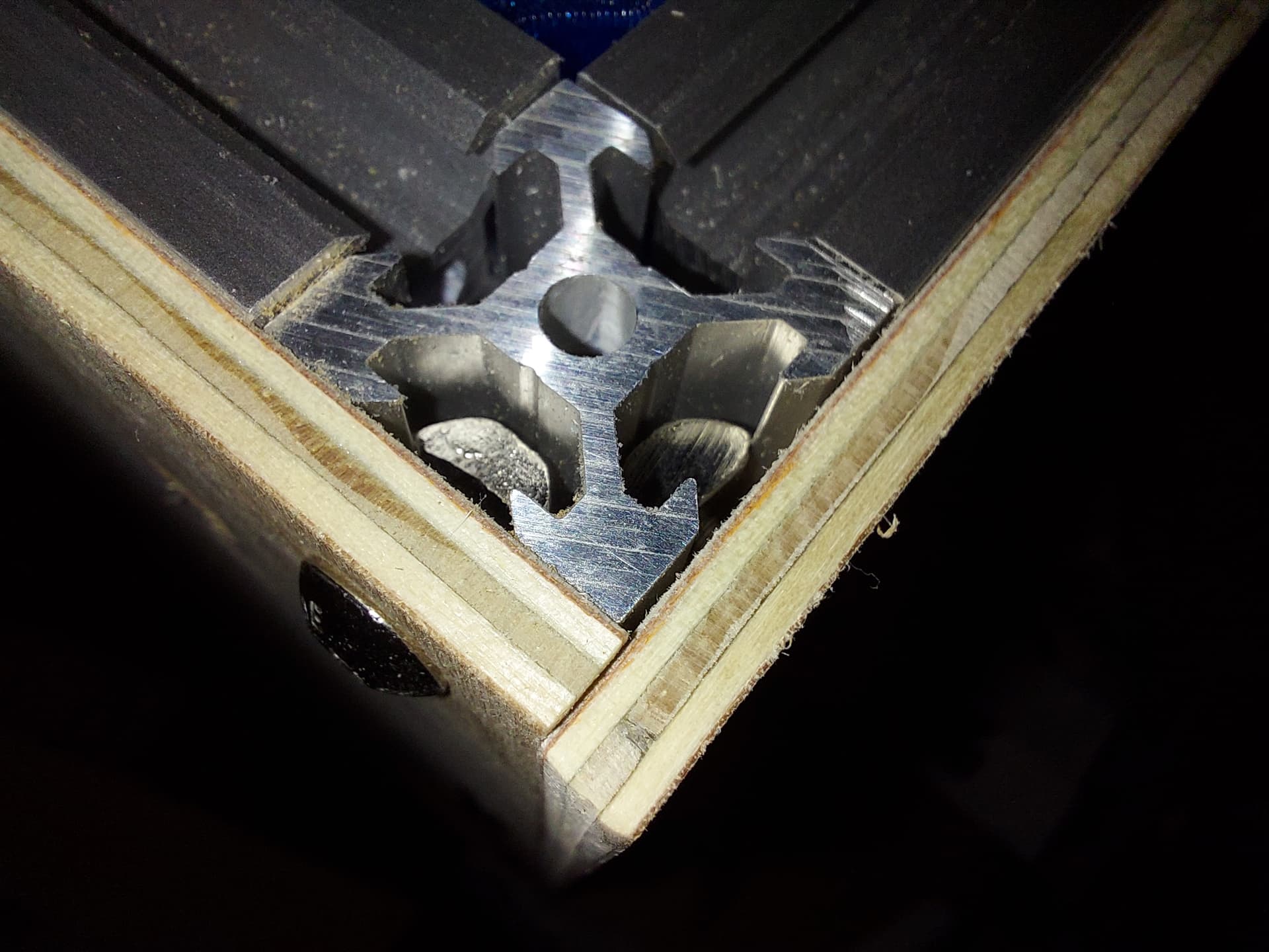
Motor wires going through the pocket
4 Likes
I am really liking this idea. One of my biggest concerns with my printers is the noise levels so I am curious how wrapping it with wood will effect the noise. On the Repeat V1, the wooden construction really amplified the stepper vibrations, but in this case the vibrations will hopefully still be alleviated through the aluminum down to the soft feet.
The pocket makes more sense now, thanks for the picture. I thought you where routing it out and then back in.
I am curious about the sound levels as well.
1 Like
I kind of expect the wood to continue to act as a sound board, but noise isnt a big concern for me. My Repeat is actually reasonably quiet, all told, but I can usually hear when it hits the home command at the end of a print job from the floor above the room that it’s in. (If that makes sense…)
1 Like
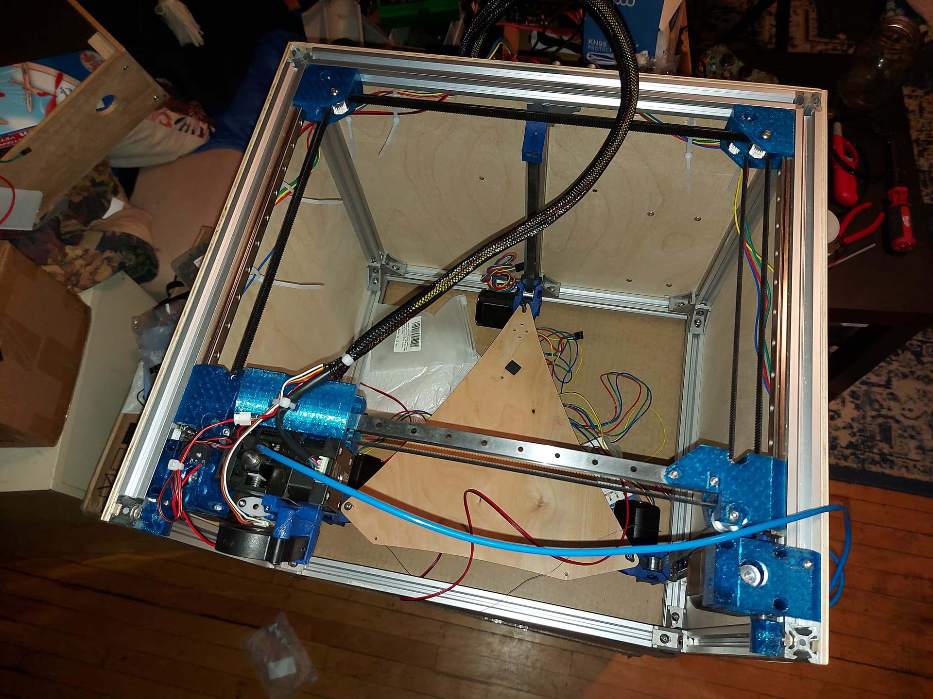
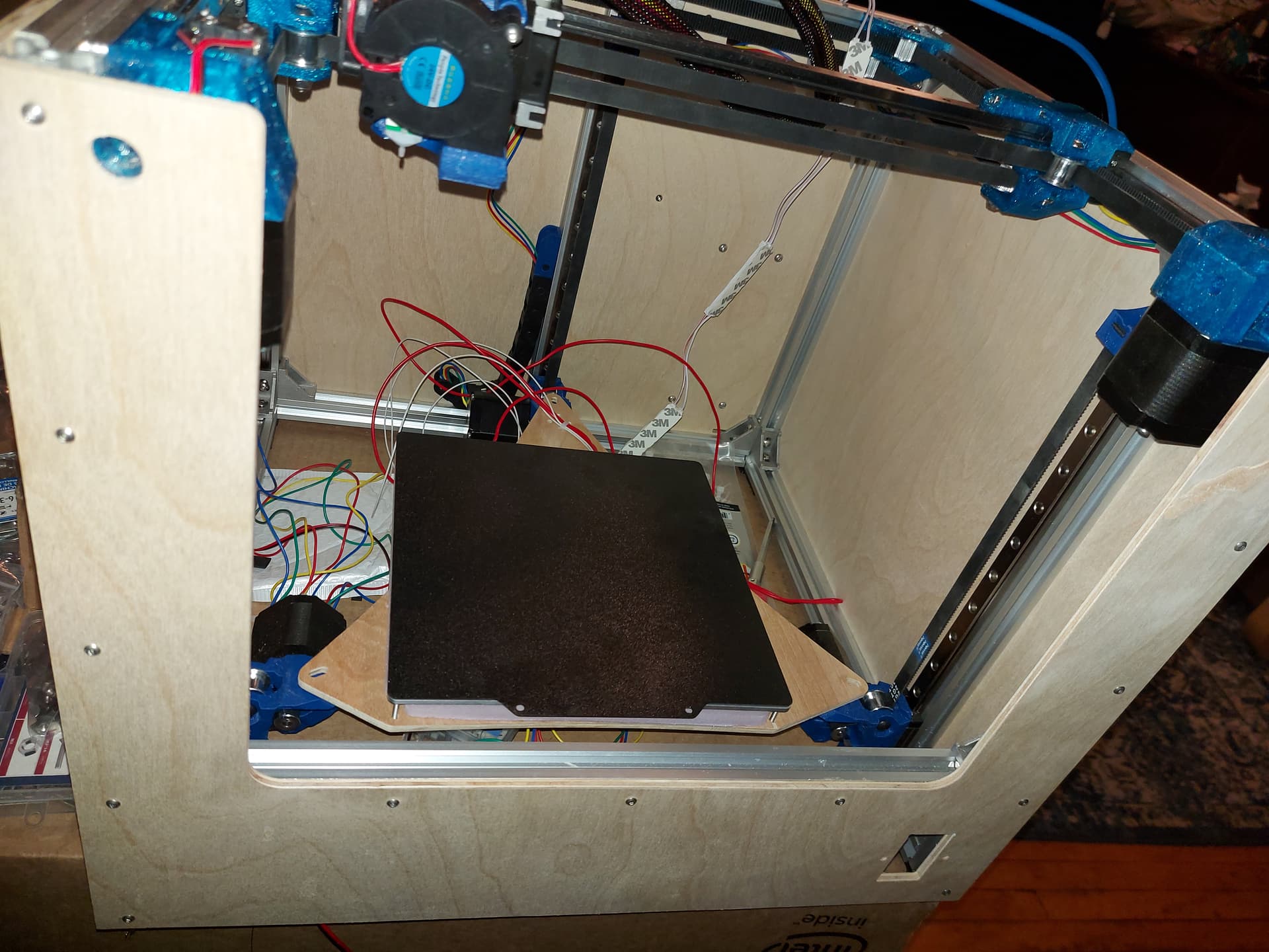
Current progress…
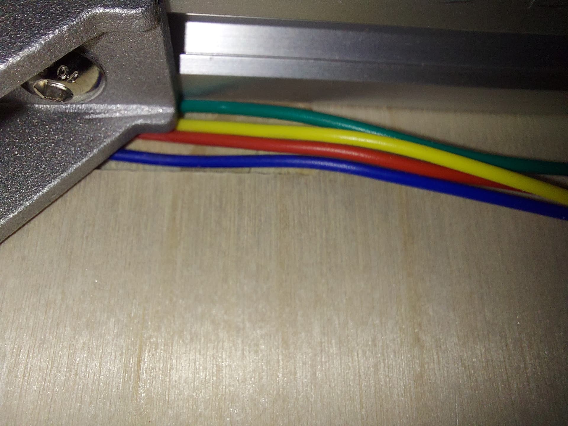
I have the wires for the hot end bundled up in a sleeve, and the second side panel on. Starting the wiring runs to the back where the Duet 3 is mounted.
I think I may run all 3 Z motors to a single drag chain at the back, since they all move with the bed, there seems to be no real need to run them all to the frame separately.
I realized that I didn’t get a thermistor with my heated bed, so I will need one. I may have one from an older printer still, so I will dig through the parts bin before I buy another one. Going to be fun trying to identify it 100% though. Maybe I can grab one from a defunct V6 hotend, at least I know what those are. That is holding up assembling the heated bed and insulator.
Edit: I haven’t tightened the zip ties on the side, which is why they aren’t clipped. Don’t judge me too harshly! It will be clipped when wire management is done!
3 Likes
It´s coming along nicely.
Seems to be a lot of decisions to make and things to do or don´t do?
To build or not to build ![]()
That is a great idea, why didn’t I think of that! Run them all the stepper closest to the control board. You could even run them out with the bed power and therm.
![]()
1 Like
That is exactly the plan. My Duet is mounted on the back of the printer, so that is where the drag chain will be.
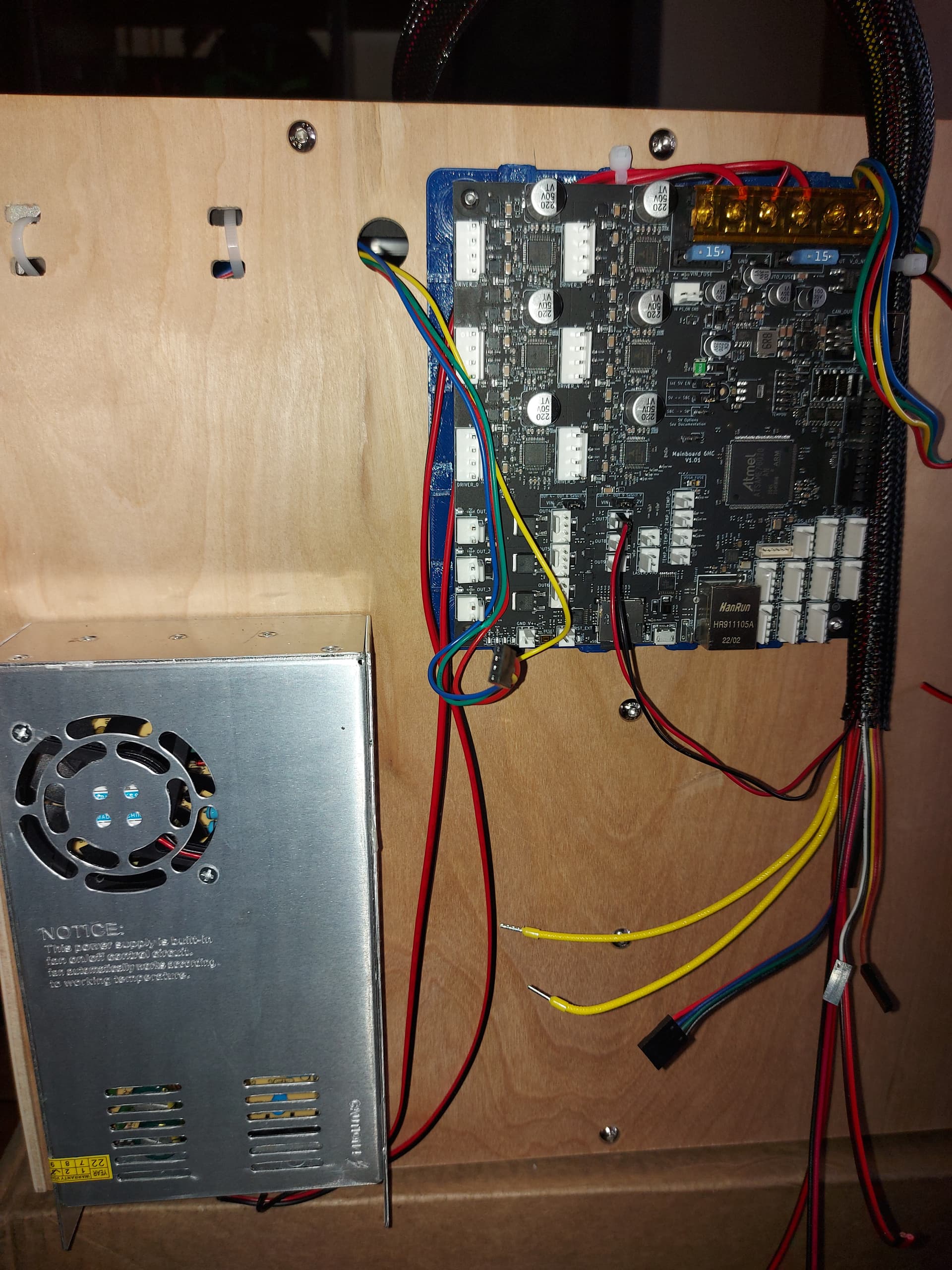
So I haven’t progressed too far in wire management just yet, of course I ran the DC power lines, but AC is still in the planning. I have some provisions for it built into the back panel CAD, but need to make a few decisions for the front. I think a power connector/switch on the front panel.
Also I want to add LED lighting. The Duet 3 has a 12V power supply, up to 800mA source for higher voltage supplies (up to 36V on the revision 1.01 that I have, up to 48V on the 1.02 that I wish I had) anyway, I should be able to add some 12V LED pucks to the inside underneath the rails without needing a separate 12V supply. I also want to add an ESP32cam for monitoring the printing process. The Duet can also supply 5V power for that, as it has a 5V supply for SBC mode. I won’t be adding a Raspberry Pi though.
One bummer with the Duet 3 6HC is that it’s wired network, not Wifi. This isn’t a big deal with where I plan for this printer to live. Ironic that the other Duet 2 printers that I have, I would have preferred wired network, but since wifi was cheaper, I went with that.
2 Likes
I did have some LED’s, I really liked them. I like the color change with temp and print time, almost useless but pretty cool nonetheless. When I started the update I forgot to put them back on. That might be a fun little project this evening.
Lol. I wasn’t thinking anything so fancy, just some white LED pucks that I can stick on a fan circuit and turn on and off. Maybe brightness control if I feel fancy. Something so that the camera can see what’s being printed is all.
If your putting them there…fade in as it gets to temp, turn green when the print is done. Just that little extra, ![]()
Sounds nice with led that react to different events! Like in the above post, with temp ready, print done, success etc.
How much work do you think it is before you are done with it?
![]() There is no such thing as “Done”…
There is no such thing as “Done”…
2 Likes
Maybe not! I was thinking about the moment where you feel that you are “satisfied” with what you have built.
1 Like
That is more unrealistic than done I guess. ![]() I always added/changed something with Schneewittchen…
I always added/changed something with Schneewittchen… ![]()
Well, what I have are 12V white LEDs, so no colour changing, but I could ramp up the brightness with temperature…
At this point it’s all just wiring, the mechanical stuff is done. I have a history of rushing at this stage and just putting stuff together “for now” and Im trying to do this differently. Probably done this weekend though
3 Likes
https://www.printables.com/model/395108-drag-chain-mounts-for-mp3dpv4
I just published the drag chain mounts for this. There is a mirror image set if people want to put a chain mount on all 3 Z axes. It is likely possible to do without, though.
This assumes that the motor wires will come out below and towards the linear rails. Hopefully the clamp system never has to see a lot of stress. I want the wires to come out upwards, so I set it up that way.
I measured the center of the Z stepper to the center of the 2020 extrusion as exactly 59mm. There isn’t much leeway for the print to stay inside the perimeter of the extrusion, .5mm nominal.
The drag chain that I have is 14mm across the mating surfaces with a 6mm joint, and 5mm clearance around the joint, so the parts are designed for that. I think this osmpretty normal for 10mm X 10mm drag chain, of course of you print your own, it may be better to remix using your own end pieces.
3 Likes
The front panel was a royal pain. I think because the 2 front uprights didn’t want to sit quite as square as I would have liked, the slide nuts kept falling out of the track and dropping. Finally I slid the cross bar up as high as I could, under the tension blocks, and put the rest of the slide nuts onto the front piece, and slid it back down into place. Sure enough the top was about 1mm “pinched” in at the top. Now it is not.
If any of the previous panels had given me this much trouble I’d have given up with only the back (which I did first.)
The panel features a 65mm cover on each side, mostly so that it can provide reinforcement to keep the pillars parallel. Also a 12.5mm hole in front of each tension block (I measured 12mm for the part around the screw head) centered on the tension screw. The cross bar on the front is 1/5 of the way up, maybe a little higher than the print bed at its lowest level, but not bad and aesthetically pleasing with where the screws are for the sides and back. There is a power entry hole there as well. I’ll need to do something about wiee manage.ent for AC power, I had intended to put power entry at the back, but wanted a switch up front anyway.
I did grab my LED pucks… The rest is wiring, and maybe a nicer solution for the filament tube
At some point I will likely want a better solution for mounting the Duet, but I think the holder that I printed will do the job nicely. Maybe that will be a 3D printed project that I can do on this printer… but probably not.
So aside from mounting the LED pucks, I think this is mechanically complete. The LEDs have 3M adhesive backing so that should be easy enough. I also want to add a mount (and power) for an ESP32cam. I believe that I can take 5V from the SBC power feed, and thst I won’t need any other signal from the Duet. The DWC has a place for a URL to grab a camera feed from. Maybe I can make the camera take a series of stills for time-lapse print footage.
4 Likes
Looks good!
You have me excited to make one like that myself. I was digging through the scrap pile yesterday, deciding on the material to use.
1 Like