MP3DP V4 build PLOG

Yeah, I see that the holes are off center, but where that hole is is off by a bit compared to the hole in the build plate, indicating that the CNC is out of square.

And… success with the TPU.


I tapped M5 threads into the bottom of the uprights and used a T nut as well. The feet make a nice addition to the frame.

I turned down the temp a bit, but still a lot of stringing with the print, so probably could be cooler yet.

3 Likes

So I got really meticulous with squaring the LR3. It’s now easily within 1mm over a 600mm (well, 597, really) square.

I did up a CAD sketch with 4 parallel lines. The outer 2 are at the distance that my belts are apart, and the inner 2 are 597mm apart, and 597mm long.

I then join them with a line across the top 597mm long anchored to the top of the inner lines and one across the bottom anchored to one corner of the outside parallel line, and the bottom of the 2 inner lines. Note that while the top and bottom lines are parallel, they are not horizontal.

Define a dimension of the 2 inner lines corner to corner.

Cut the square with the CNC and measure the diagonals. The driven dimension of the free end of the bottom line to the base tells me how far to make the adjustment to the Y endstop.

Result, I cut a piece that is as close to square as I can measure. I only have mm markings on the tape, but estimate that it is less than 0.25mm out when measures corner to corner.

What has this to do with the printer?


So I figure that the extrusion will hold the plywood flat and the plywood will hold the extrusion square.

2 Likes

Music to my ears!

So you are making the extrusions still, but skinning it in ply? I think you are on to something. Using them both makes for a best of both world’s situation…and gets rid of most of the corner braces.

Freaking genius!

1 Like

Nice! Look forward to seeing how turns out. What ply thickness?

I’m not doing all of the faces, the top and bottom will remain open, very probably the front, though that remains to be determined. I may just do the lower part on the front below the cross bar.

It’s not a new idea, the Railcore was designed this way, using 1515 extrusion and a skin surface to make the structure more rigid. I don’t remember what material the Railcore was originally specced with, but the idea was the same, like a torsion box, using the skin to reinforce the structure and keep it from deforming.

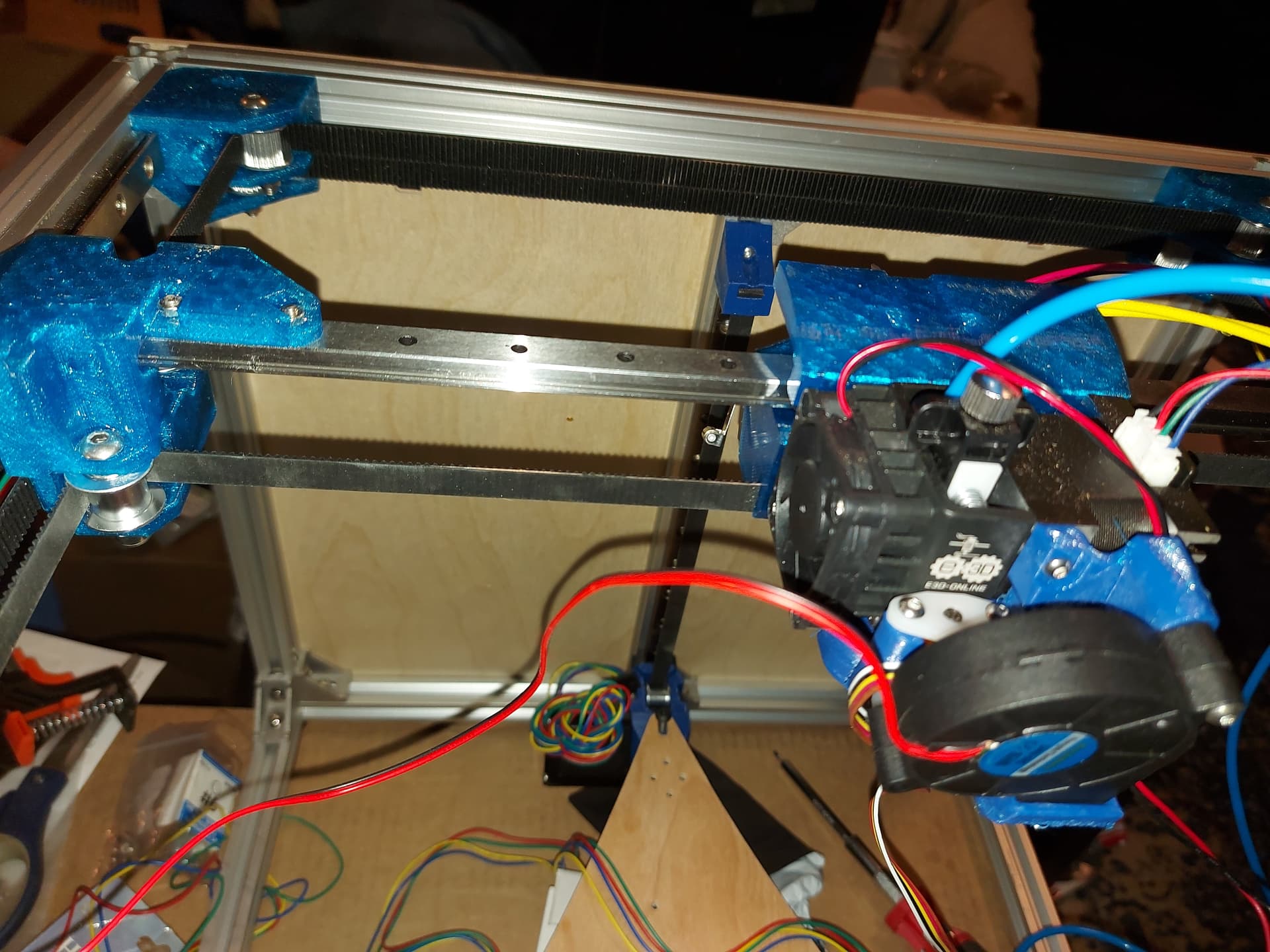
With just the back plate though the whole frame feels more solid, and the back is like a granite slab. This is with 5.5mm plywood, but I’m pretty sure it would be amazing in 1/8" acrylic, as well.

2 Likes

Looks good. Do you have any acrylic?

I actually knew the founders of Park Tools 100 years ago!

Great folks, buy more!

1 Like

Next trick is the sides. Trying to visualize how I want these to run.

The wires for the alpha/beta motors need to get past the uprights for the Z motors, so I’m thinking a pocket that passes by the pillar to keep them inside the outer skin, but outside the extrusion to keep the wire clear of the Z linear rail. Put it 30-40mm below the top, maybe 50mm wide and 10mm high, 3mm deep. Should be enough room for the motor wires and Y end stop wire that way.

Given the way that the Duet 3 is set up, all 6 motor wires need extensions, or at least new plugs for the board. I’ve got a bit of decision paralysis with this one. Cut the wires and splice in extensions, or put male dupont connectors on extension harnesses… both have merits, and drawbacks. Well, if the main drawback is that I can’t change mainboards, I suppose cut and splice isn’t too bad a choice, but I hate wasting wire, so that means that I need to have all of the wiring figured out before I start with the extensions. Bleah. :face_vomiting:

I also appear to be put of 22AWG wire for the homing switches. More coming from Amazon, but it is yet another delay.

Anyway, next step seems to be figuring out what features I need for the side panels. I put those handles on the Repeat, and used them pretty much once. :rofl: I thought I’d be moving the printer from time to time, but basically I never do.

A camera mount seems like a good idea…

I have a bunch of 10x10 drag chain left over, but no ends. I figure it could be useful for the Z motors, maybe I’ll print up some mounts to connect it to the motors and the Z uprights. Wire sleeve is probably good enough, but I have it and drag chain will 100% guarantee that the wire doesn’t get in the way or get snagged. Same I guess for the heated bed wiring, but it can go in the same drag chain as the 3rd Z motor.

Anyway, these are the ideas I have now. I’m sure things will change.

3 Likes

Is there a cheaper alternative to the Duet 3?

I run the XY (AB) stepper wires above the Z belt tension block, over the rail on the inside. I thought about making a more elegant screw in piece but, you know me, zip tie if needed.

1 Like

I thought as much, but if I’m skinning the box, the pocket seems to make more sense, less that can possibly go wrong. A zip tie slot on the Z belt holder might be a good addition for those who aren’t skinning the frame.

Well, there are the Chinese clones, the genuine ones are pretty spendy, but the 2oz copper is nice. I also like to support the developers when I can. My Duet 3 doesn’t have wifi, just wired network. Mine is also a revision behind current.

The SKR Pro also runs the RRF firmware, just needs an ESP add on, about $10 to add the wifi and DWC. I have a set installed, but haven’t configured it. It’s probably the cheapest ticket to the RRF field with 6 motor drivers.

2 Likes

Need more plywood…


I cut this piece, you can see the pocket for passing through the motor and end stop wires, and a set of holes for zipties to secure them. I didn’t put any handles on this printer so the side is smooth. The holes for the front and back uprights are 3mm, the rest are 5mm, because that’s the hardware I have left.

3 Likes


One side panel installed. Will do more when I get more 5.5mm plywood


Motor wires going through the pocket

4 Likes

I am really liking this idea. One of my biggest concerns with my printers is the noise levels so I am curious how wrapping it with wood will effect the noise. On the Repeat V1, the wooden construction really amplified the stepper vibrations, but in this case the vibrations will hopefully still be alleviated through the aluminum down to the soft feet.

The pocket makes more sense now, thanks for the picture. I thought you where routing it out and then back in.

I am curious about the sound levels as well.

1 Like

I kind of expect the wood to continue to act as a sound board, but noise isnt a big concern for me. My Repeat is actually reasonably quiet, all told, but I can usually hear when it hits the home command at the end of a print job from the floor above the room that it’s in. (If that makes sense…)

1 Like


Current progress…

I have the wires for the hot end bundled up in a sleeve, and the second side panel on. Starting the wiring runs to the back where the Duet 3 is mounted.

I think I may run all 3 Z motors to a single drag chain at the back, since they all move with the bed, there seems to be no real need to run them all to the frame separately.

I realized that I didn’t get a thermistor with my heated bed, so I will need one. I may have one from an older printer still, so I will dig through the parts bin before I buy another one. Going to be fun trying to identify it 100% though. Maybe I can grab one from a defunct V6 hotend, at least I know what those are. That is holding up assembling the heated bed and insulator.

Edit: I haven’t tightened the zip ties on the side, which is why they aren’t clipped. Don’t judge me too harshly! It will be clipped when wire management is done!

3 Likes

It´s coming along nicely.

Seems to be a lot of decisions to make and things to do or don´t do?

To build or not to build :stuck_out_tongue:

That is a great idea, why didn’t I think of that! Run them all the stepper closest to the control board. You could even run them out with the bed power and therm.

:eyes:

1 Like