MP3DP v4 - Aza's build

Agree, will probably use silicone if anything at all, no idea if it’ll have noticable impact.

So far the consensus on my printer’s discord is corner brackets are the squarest way to go. The kit comes with corner cubes, but they’re not always square, and the ends of the extrusion isn’t always square either. The general method is to get it mostly tight, add the side panels, then use a 123 block, or other known good square to square the corners and tighten the panels, then the cubes. If you’re not doing side panels, the corner brackets are at least adjustable enough to make the frame square.

3 Likes

Cheers for the assembly guidance @barry99705, will follow your tightening sequence process.

RailCore discord at RailCore® ?

1 Like

Just like that!

I did blind joints and rigged up an end squaring jig on my belt sander. I think your way makes lots of sense if you dont have the other options.

Hey @probrwr (or anyone else), with a revo hotend and EBB CAN Bus, my build is going to end up similar to yours.

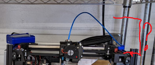
What height/gap above the top Y extrusion is needed to accommodate the hotend/extruder/can-bus and ptfe tube feeding filament from spool-to-hotend-carriage? Planning to enclose, currently have 200mm of extrusion going above the stock Y extrusions, which just looks silly at the moment.

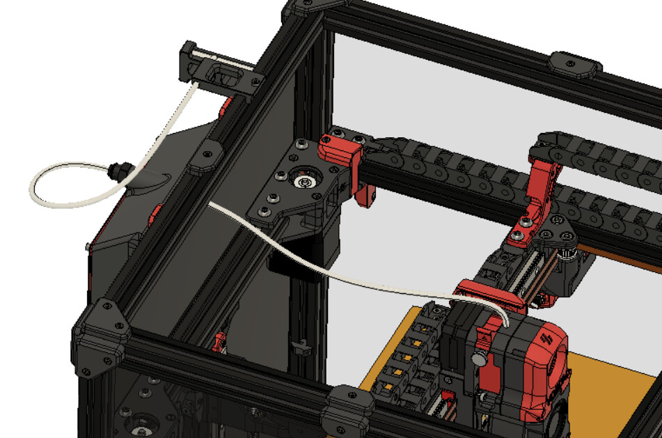
Below is pic of Ryan’s open build

image

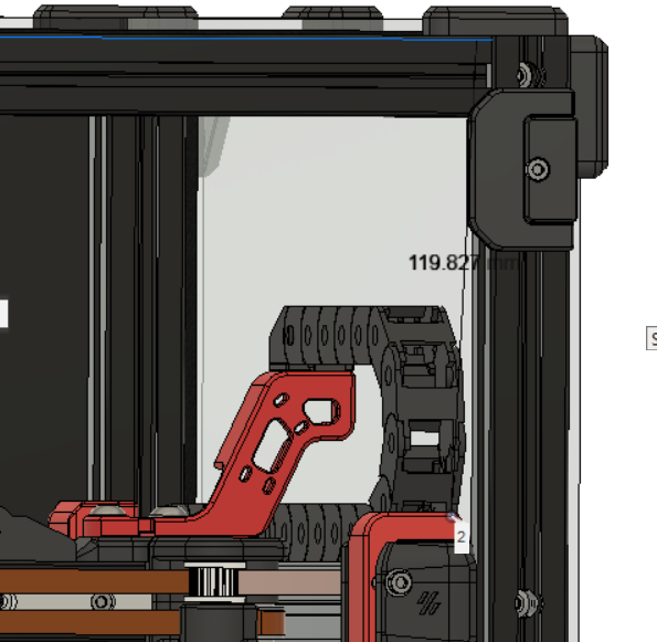
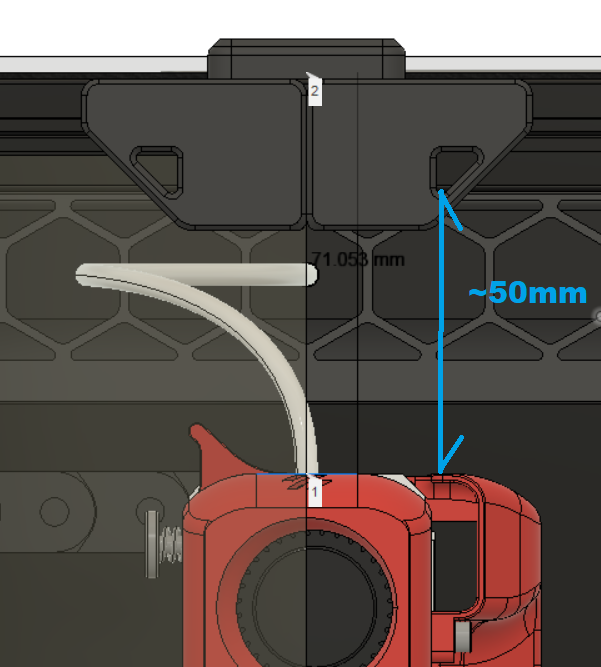
Voron Trident seems to have about 120mm from gantry, but their hotend is different to our BIQU REVO setups. They only plan for PTFE to take 40-50mm height to turn as they route and coil out the back.

1 Like

I feel like the 120 should be good. The purpose of the tube is to do the guiding and the filament SHOULD be flexible. Maybe put some filament in a bowden tube and see how far it will flex and still move.

I have been thinking about this also and feel like the cheaper sloppy fitting tube is a way better option than something like Capricorn.

Thanks Mike! Another option is to delay, or at least partially delay, deciding by going with separate lid, similar to Pantheon…

Although… Looks like rear Z extrusion/support with hinge goes up to at least the height of the gantry components and PTFE carrying filament. Keeping front Z extrusion flush with top Y extrusion looks good to me, if making a flip lid, or lift off lid. Nice look, but…

For me space is a premium, so am wanting to densely rack/shelf mount my printer with other stuff, so this wouldn’t be practical for dense/confined spaces since the lid needs significant vertical space to open up.

Decision… Going with something in between… Lid that can lift up, or slide forwards (if racked), doing this by making a lid with no back. Hinge can be optional/removable. Rear upright Z extrusion will be ~120-150mm taller than top Y extrusion. Will keep front upright Z extrusions flush with top Y extrusion. Might reuse my LR3 case design for the lid structure.

1 Like

I decided I’m going with a separate lid on mine. I’m going to hinge it on the back so I can lift the lid up when I need to work on the extruder.

1 Like

yep!

I like the idea of a sliding lid! I plan on using a panel clamp design I can up with for my Hypercube to hold the side panels on. If I mod that design to have a lip the extends up it would serve as a guide. Now I wish I had extended the back posts up also.

Consider modeling interior panels if you’re building with those, otherwise you end up with holes not aligning like me :man_facepalming:

Fortunately I only messed up on Ply, and not $$$ Poly. Will reuse the failed Ply to make @Tokoloshe’s cleat containers or something

1 Like

I almost did, but I had to print something where square matters on my old printer that I built this way, and it wasn’t really square. Not off by much, but I could see it when I checked.

That was enough motivation for me to buy extrusion. Now, if I could just get out there and BUILD it.

1 Like

There something similar to BLTouch but for skew/squarifying/calibrating XY, something that can compensate for crappy assembly, and/or unstable material (skew compensating post processor)? E.g. Camera + ChatGPT since that can do everything.

Ended up using Polycarbonate for interior side panels, will use on front too. Will save some $$ and use ply on the back to help square the frame. All the cool kids are using HDPE it seems.

Excessively long legs to accommodate electrical stuff underneath. Taller uprights on the rear for TBD lid.

Ah yes, I forgot about the skew correction. At any rate, they’re are some things I don’t like about that printer anyway. Once I replace it with the repeat, I’ll probably see if I still have the parts to put my ender back together and call it good. After all, that LR3 ain’t gonna build itself…

The MK3 can do it with the lines on the bed. Don’t ask me specifically though.

Got Polycarbonate, Ply and Sheet metal panels. What else? Am not doing HDPE. Contemplating dumpster diving a local countertop company…

2 Likes

problem: On front right stepper mount, button head of the M3 ended up being grinded by the M5 crossing overhead. This caused M3 removal to be slow/frustrating later on.

I was removing the M3 after realizing stepper couldn’t freely rotate because grub screws are too proud and knock into body of the Stepper Mount .

fix: I probably didn’t seat/fasten the M3 enough, button heads on my M3’s are ~2.3mm tall.
@vicious1 Consider more vertical clearance for head of the front right M3 x 10mm bolt that sneaks in first, underneath the M5 x 30mm bolt, that pull on the stepper mounts, so belt tension can be adjusted.

Learnings / Fluff-ups:

  • IF using interior panels, ensure panels have slotted holes drilled allowing stepper mount to freely slide back and forth as tension is adjusted using the M5 bolts going from the Tension Block XY to the Stepper Mount
  • Ensure pulley mounted in correct orientation to stepper shaft, see build gallery.
  • Use 1 grub screw for the stepper pulleys, with thread locker (use Medium, not high strength, incase you’re like me and end up correcting/redoing work). Ensure grub screw is pressed in deep as possible on flat section of the shaft. Reason… 2nd grub screw, or insufficiently deep screws will hit the 3D printed part, preventing stepper rotation.
  • After mounting Pulley to Stepper with the 1 grub screw, dry fit stepper into the stepper mount. Ensure stepper can rotate freely and that grub screw isn’t proud/knocking into printed stepper mount.
  • Ensure Tension Block XY is loosely fastened to the Left|Right Stepper Mount, before the Stepper Mount is attached to extrusion/frame.

**Edit 2023-04-13 : ** Should have used 8mm instead of 10mm for that front right M3, bolt would have cleared underneath the M5.

1 Like

That one bit me too. Getting the nut in the groove after attaching the stepper mount to the extrusion was very difficult.

1 Like

Yeah, getting M5 nut in the slot took me a while, adjustable pliers eventually worked for me. Managed to slightly damage/indent the printed part in the process. Not a big deal, cleaned up with box cutter blade, but I should have padded the adjustable pliers before squeezing nut into place.

M5 nut slips out when loosening, so might print small ‘C’ shaped filler block to keep the M5 nut in place but allow M5 bolt to pass through. The interior panel will prevent filler block from falling out.

1 Like