MP3DP v4 - Aza's build

I haven’t tried yet, but I think because of the nature/flakiness of the cork a really small diameter endmill, something like a 1.5mm endmill would do the trick and give you a nice edge if you are just cutting it, now as far as milling a pocket maybe a 4 flute endmill??
Like I said, I haven’t tried yet…

1 Like

  • Mounted 260x260mm 1/4" thick Alu bed. Bed started as 12"x12", instead of using LR3, used circular saw, drill press and orbital sander (to ease edges/corners with 80 to 120 grit, enough to not be stabby).
  • Attached same foam used by others to the 1/4" Alu plate. Used HVAC foil tape, silicone adhesive and zip-ties thru ply bed support plate to help secure/stress-relief wiring and butt connectors.
  • Mounted separate drag chains for heater bed wiring. Spring mounted drag chains to bed since bed can tilt. Tested thermal fuse and heat bed resistance, before, during, after wiring and crimping up. In-lined thermal fuse on mains wire going to mains Live.
  • Experimenting with dupont-to-dupont connector so controller box can be easily removed.

Wiring up, installing and configuring Raspberry Pi, Octopus v1.1, Klipper and MainSail…

  • Powering Pi using 2 pairs of wires from Octopus’s Pi pins.
  • Trying out cheap 3.5" TFT resistive touch screen for now. Screen’s connector uses subset of the pins it physically covers. So, am using a 2x20 pin splitter so 5V, Gnd and UART tx/rx pins can be forked off to the Octopus for power and serial comms.

Currently trying to cobble a Klipper printer.cfg together…

2023/5/7 Edit: Wiring setup above may not work well with EBB36 CANBUS setup, am still learning/figuring out, but am seeing some people put CAN BUS hats/adaptor on their Pi. Was hoping to connect Octopus’s CAN Bus port directly to EBB36, but there’s caveats/details… Sharing here incase someone encounters similar challenge, or has figured out already? Was hoping Octopus and Pi remain connected via UART, but USB cable might be needed instead. Trying to avoid USB cables to help make the enclosure/case smaller.

2023/5/9 Edit: Not much time spent or progress, but am digging around Voron Discord’s #can_bus_depot channel, looking at CAN Boot, CAN Bus projects and misc info out there. Seems possible to wire EBB36 directly to Octopus CAN Bus port, but some people experienced reliability issues (packet drops and disconnects) and end up wiring to Pi via a U2C (USB to CAN Bus) module, or Pi Hat. Not clear if people experienced problems due to poor wiring/connections. Will ensure at least a twisted pair, decent gauge stranded copper (not CCA) is used for the data lines, reason is protocol uses “differential signalling”. Maybe increase sender buffer sizes if overflows, hopefully not needed. Would love to know if anyone here is happily/unhappily wired directly from Octopus to an EBB?

2023/5/14 Edit: Been busy with non V1E projects, but finally making progress with Klipper, MainSail, Octopus with CANBus. Setup EBB36 v1.2 to Octopus topic on Klipper’s discourse forum has been helpful.

  • If using EBB36/EBB42, be sure to use the correct crimp inserts with the Molex Micro-Fit 3mm pitch connector that supplies power and CANBus data. Could be better documented, submitted feedback.

4 Likes

If you end up using a usb cable, I’ve had success with one of these. It was pretty small and the angled connector helped keep the setup tight.

YCS basics Black 6 Inch USB 2.0 High Speed Printer/Scanner Right Angle Cable https://a.co/d/aozMB40

2 Likes

Tried and failed to get EBB36, Octopus, Pi working. Not seeing any EBB CanBus traffic. Tried various things, still investigating, details at…

Currently trying out a U2C (USB to CanBus adapter) to help workaround and/or narrow down root cause.

Any guidance on monitoring/debugging code on EBB appreciated. Cheers!

2 Likes

The CAN electrical signal is very noise resistant, but it is very different from regular digital IO. The two lines switch away from ground and they generally operate +2.5V and -2.5V from ground (IIRC). So you can’t really tell from a multimeter what is happening. The oscilliscope signal you have looks about right, where the two signals separate.


The baud rate is really important. You have to get that right on all the members of the bus or you will get junk.

Each message on the can bus is small. 8 bytes of data and 4 bytes (31bit, IIRC) of header. You might be able to see some of those if you just look at the can data without the scripts. You shouldn’t get even junk data if you have the wrong bandwidth set.

To flash over CAN, there needs to be a specific protocol agreed to by both sides. There isn’t a standard can flash protocol. So you need at least a bootloader on the EBB board. Is there another way to flash the mcu? Isp or uart?

2 Likes

Sometimes, it seems like Dupont connectors want to repel each other and make for loose unreliable connection.

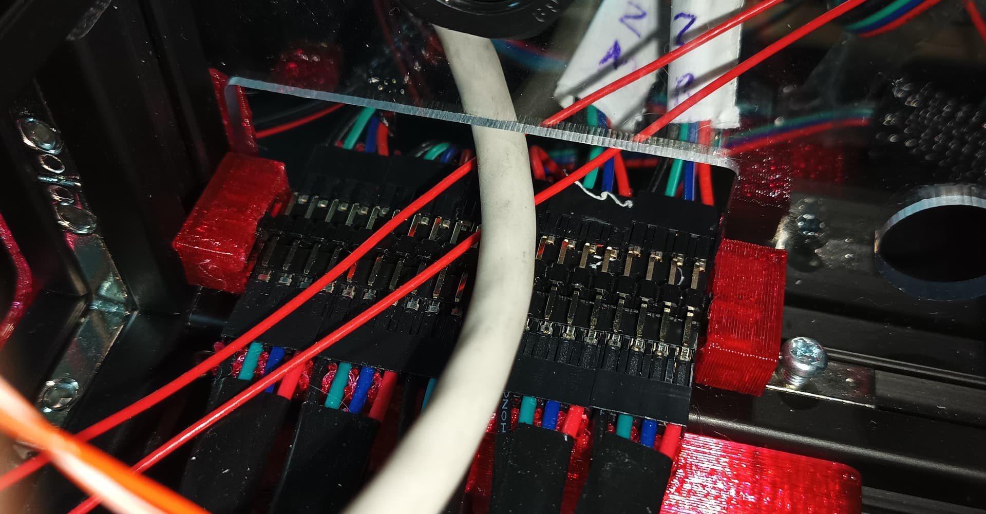
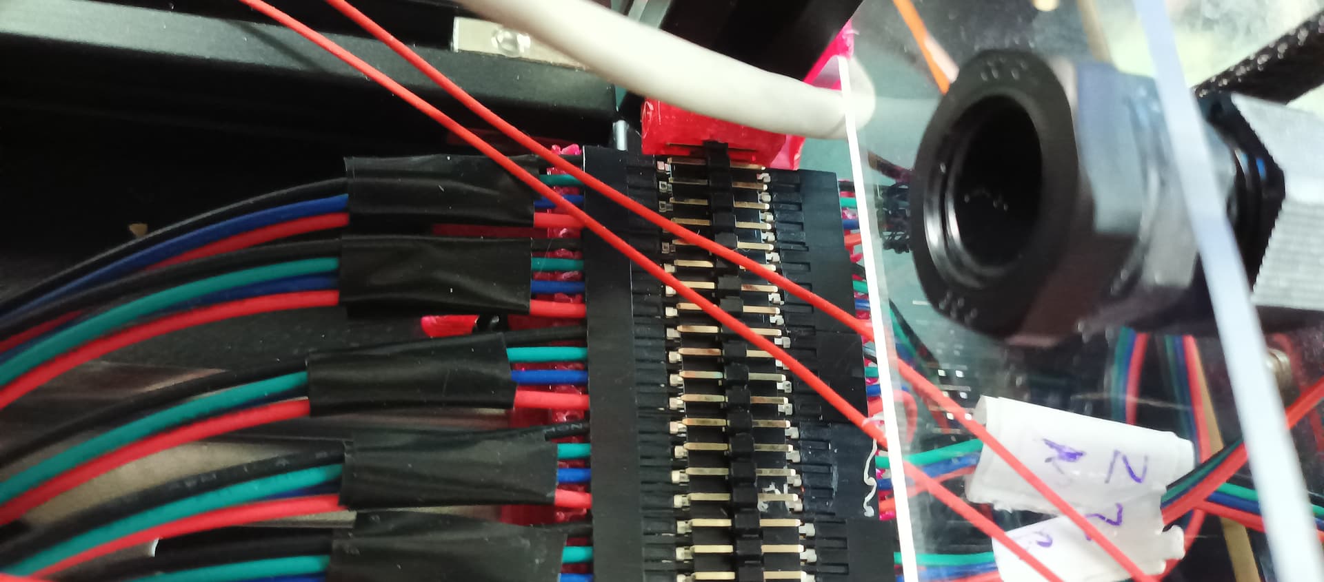
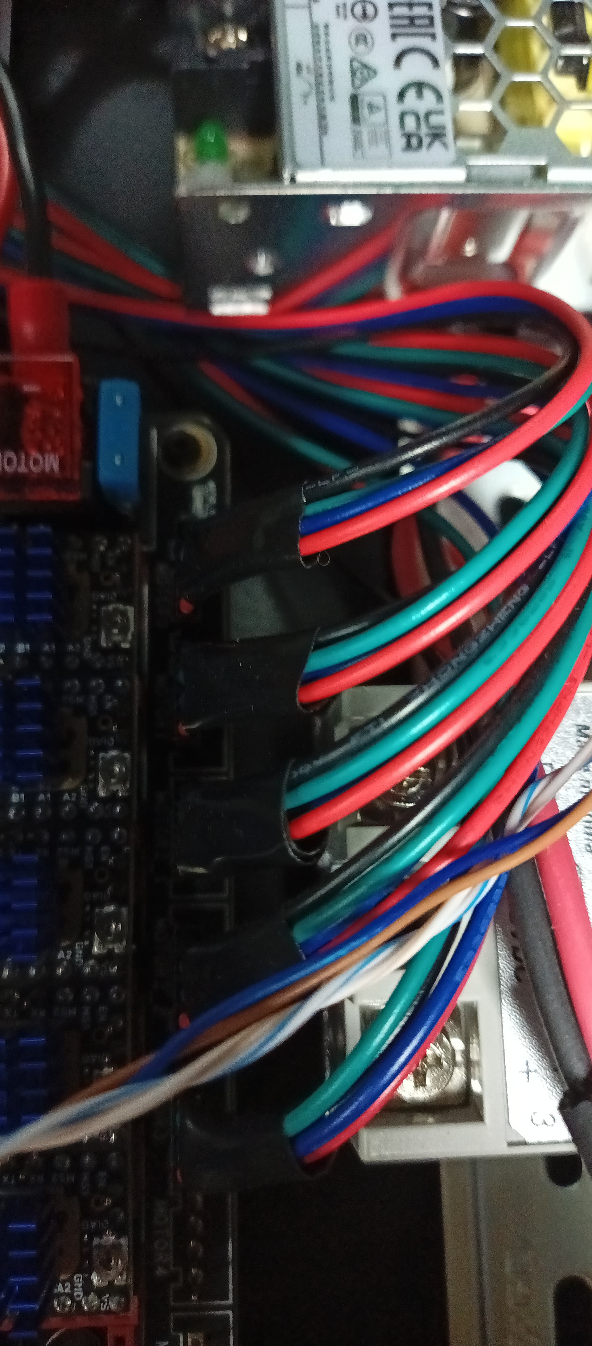
But Dupont connectors are also super easy to work with. Am experimenting with using printed shroud to help at least secure the bottom row of 2 rows of 20 pins (5x 4 wire steppers…). Am using this to extend wiring at the Controller/PSU box, internally am using premade Dupont wires. Easy to use, but don’t know how reliable this is yet, sharing incase it helps others… Top row of wires needs a top clam/shroud peice, will make one if/when needed. Not much to it, just held in place with 1 T-Nut.


Shared files at v1engineering-mods/mp3dp-v4/mods/dupont-mount at main · aaronse/v1engineering-mods · GitHub. Do not consider these polished tested finished pieces. Instead, view them as a snapshot/mirror of my in-progress build. Shared to help others, and get feedback for how to do stuff better. Cheers!

4 Likes

Somewhere in this forum there is an OpenSCAD clamp for dupont connectors that can work from 1 to n pins and clamp the connectors together. The limitation on them is basically the size of your printer bed. I can’t find it though. :stuck_out_tongue:

There are a couple on Printables, but not the scaleable one that I was thinking of (Or at least I haven’t found it.)

3 Likes

I remember it, and I don’t think this is it, but here’s a link anyway!

2 Likes

Finally have Pi4 → Octopus v1.1 → EBB36 successfully communicating via Klipper/CanBoot over CANBus. Learnt a bunch about CANBus, 'bit trial by fire, had to buy a 2nd EBB36… Still waiting for a board killer badge :slight_smile:

3 Likes

That’s a great step forward!
Can you document the final setup you have?
I can’t wait to see your printer running with that setup.

3 Likes

Will do, when ‘done’ enough to claim a serial number.

For now, have started uploading backup/snapshots of my (inprogress) Klipper printer.cfg to github.

23-05-26 Edit: Bought BIQU EBB36 incorrectly thinking that the version with Max31865 onboard provides more accurate, reliable, stable thermostat readings. Sounds great right?

I was wrong, ended up burning time on config/setup because Max31865 isn’t compatible/needed for the NTC based thermistor inside the BIQU H2 V2S Revo’s hotend. Full details in…

2 Likes

Worked through misc CANBus and Klipper setup/wiring issues. Belted, powered up and zipping around…

Intentionally leaving nozzle and PEI plate off until I understand z_tilt and mesh calibration settings better.

Still figuring out Klipper z_tilt settings and behavior. Tilt adjustment ends up making things worse, maybe I need to negate/flip direction a setting somewhere. Suggestions appreciated!

[z_tilt] #AZA doc @ https://www.klipper3d.org/Config_Reference.html?h=pixel#z_tilt
z_positions: # Pivot Points
  -20,27
  135, 303
  292, 27

#center_Y186
points:
  35, 35
  135, 245
  245, 35

speed: 100
horizontal_move_z: 10
retries: 10
retry_tolerance: 0.005

Technically, think I can claim a serial number as soon as it squirts hot plastic?

Edit: Chris Riley “Klipper - PID Tune - Dial In Your Printer - Chris’s Basement - 2022” helped me tune the Heater_Bed and PID based Extruder/HeaterBed temperature control settings.

2 Likes

That’s what Ryan said in the serial number post LOL. Printer is looking good! Hopefully I can get past all my self inflicted issues soon LOL

2 Likes

I have no idea about klipper but marlin has a sort of PID style gain for it’s leveling estimates, or you can do the coordinates of the mount points. We use the gains and if you are a bit too high it gets worse with each level. So I would say either your mount coordinates are off (using the screw locations for the mount plate, not the rail correct?), or your gains are too high.

I hope that helps at all?

I have some klipper stuff ready to go plug in but have not done much but look at it running and glanced at a config.

2 Likes

Missing space?
-20, 27

1 Like

@gpagnozzi @probrwr and any other MP3DP v3/V4 folks using Klipper.

Are you using z_tilt and/or Bed Mesh to probe/level/calibrate your beds before printing?

Curious if z_tilt works for others. Currently digging thru klipper code tracing/debugging z_tilt, so feels like I must be missing something simple. Cheers!

1 Like

Z-Tilt on every print.
And call the saved “ Default “ bed mesh.

Once you do the initial setup, z-tilt and save the bed mesh, you don’t need to do bed mesh before every print. Just the z-tilt.
I’m not home to post my current print.cfg but if you look at the one I posted couple months back you can see that start print section call for the z-tilt and the saved bed mesh.

2 Likes

Nice! Thanks for the info @gpagnozzi, really appreciate confirmation that [z_tilt] is expected to work.

Your post helped me take another look at my setup and wiring again… Turns out I’d messed up the wiring and plugged one of the steppers into motor2_2 :man_facepalming:, instead of skipping, similar to what we do for SKR1.2 Pro.

Fixed and finally have z_tilt working now :slight_smile: Here’s the stepper wiring that’s working for me…

Seems to take z-tilt 6 attempts to satisfy the retry_tolerance: 0.005 value. Am double checking distances/dimensions of my pivot points to see if that helps. Also moving probe positions as close as possible to pivot points should help.

Even so, I (a Klipper Noob) don’t understand why 0.005 tolerance is needed given the 0.645mm variance observed for my Alu plate. Measured at room temp, no PEI/magnetic layer yet, bought from amzn. Probably not Cast Alu, which I learned would have been more stable during hot-cold cycles. I may also have warped the plate further when cutting down to size with angle grinder. Am still learning what mesh variance most people find acceptable?

Looking at ways to speed up since z-tilt is needed before each print. e.g. Sleep intervals between probe readings seem unnecessarily long (~1s), looking into that too…

Am loosening retry_tolerance: to 0.04 for now until I learn better, and/or someone informs me? Tolerance of 0.04 is helping z-tilt process complete faster with just ~2 attempts.

Cheers!

2 Likes

Z2 port should have jumpers it is wired in series. It should not work without them.

1 Like

0.04mm across a 250mm bed is very good in my opinion. Make sure to let the bed heat soak for a few minutes to stabilize beofre leveling, make sure it has a bit of room to grow and shrink.

2 Likes