MP3DP v4 - Aza's build

I have that pause. I have a 24VDC heater. It isn’t super fast, but I did automated probing and found that the Z offset continued to change for 4-5mins. So I have gcode to wait 6. It is annoying when I am tuning something. But I do like not having failed prints anymore.

I want to get one of those thick aluminum pei covered plates, but I thinn I need to go to AC heating if I do. I am just not as sure about the safety of them. But I will take the plunge someday.

2 Likes

Mine heats as it does the preprint bed tramming probes.

2 Likes

I’m the same.

My startup gcode is:

turn on the bed heater
turn on the hot end
home x, y
home z/level bed
purge hot end ( move to the edge of the bed, bring the bed really close to the hot end tip, extrude a touch of plastic, then move across the edge of the bed to wipe off the excess )

The temperature graph shows the bed’s temp is pretty stable by the time it gets to the home z command. There are some pretty big swings in the graph prior to that point where I assume the aluminum plate is soaking the heat from the bed heater.

3 Likes

True story: it does tickle in water. Was helping a neighbor of a friend move some stuff during a flood, and that’s how I found out his power was still on…

1 Like

I wrote up my procedure here somewhere. I had something calling G38 over serial, and then a script to read the results. So it was probing Z, which doesn’t change the Z position like home does, and printing the distance to the bed. I plotted the Z distance over time. This was from the middle of the bed.

This would actually be a decent octoprint plugin. Something that just had a start/stop button that would probe constantly while recording the results. Bonus points for plotting it, or adding configuration like period.

IIRC, I did it with the command line and the usb.

2 Likes

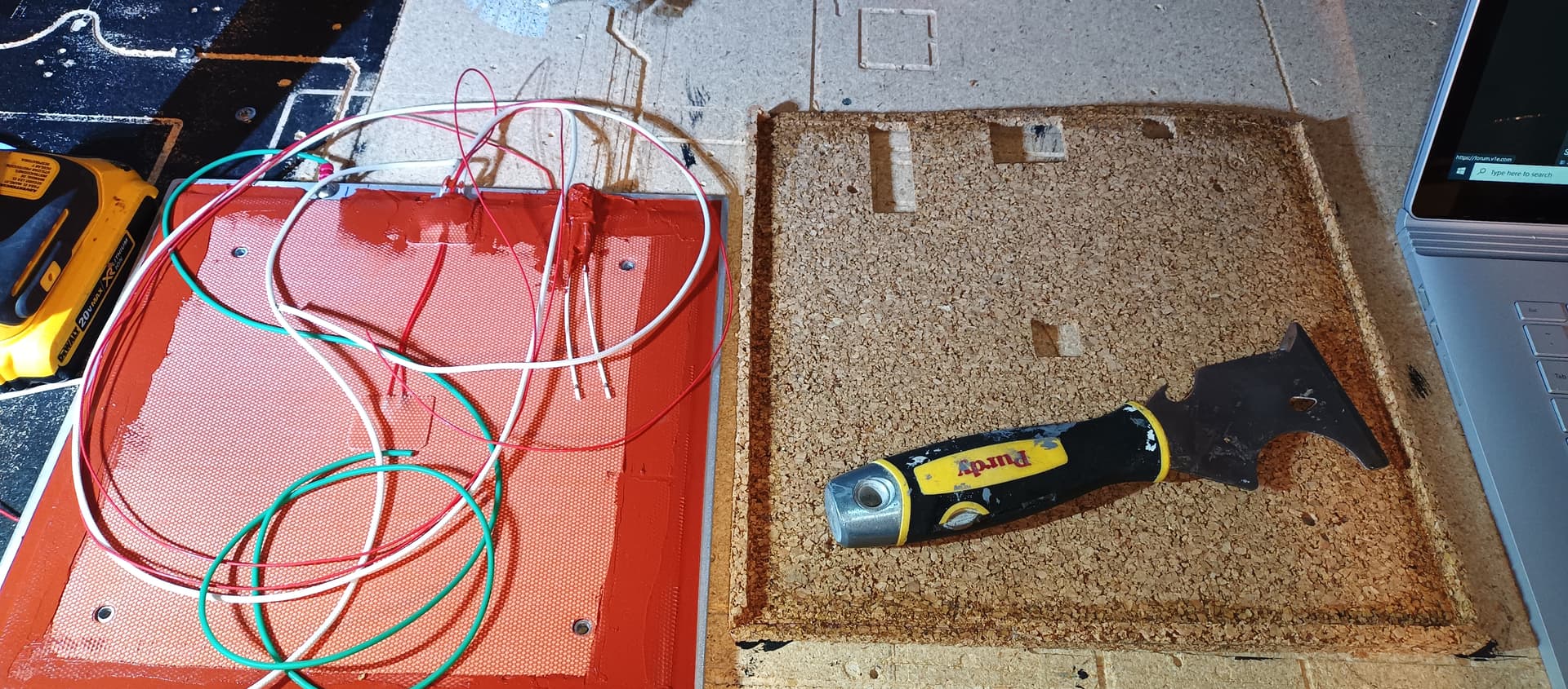
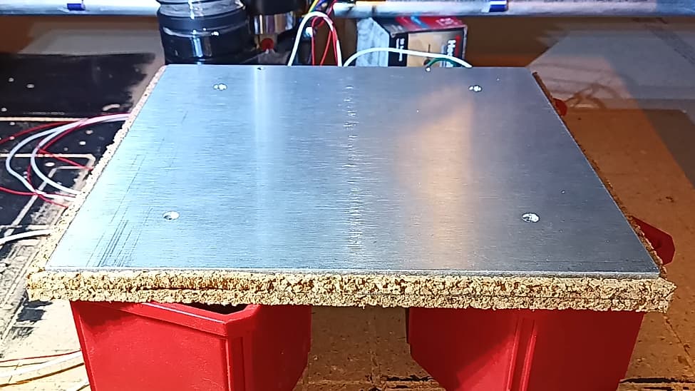
Tried, but failed to mill acceptable cork “Bed Snugger” ™. Fits like a decrepit worn out glove, fixable with silicone, but is too crumbly for me. So, have ordered some popular foam insulation that @Jonathjon, @niget2002 are using.

Left dxf and gcode files on my repo incase someone wants to have a go.

Single flute downcut carbide to help pin down the cork, 15mm/s, lowest makita speed, screwed stock down with just 4 screw near the corners, but clear of where mill end was expected to pass (~20mm in from each corner).

4 Likes

That looks like the cleanest cork I have seen. If you wrapped the edges in kapton, it would be pretty good, I think.

4 Likes

I thought the thing to do these days was to seal the edges in blue resin for that ‘live edge river’ look.

1 Like

I agree that cork looks really clean. Cleaner than what’s under my TAZ build plate (which works GREAT, by the way)

1 Like

Appreciate the feedback on cork being great to use. The photo I shared was unintentionally deceptive… The smooth material you see is probably material that wasn’t even milled :slight_smile:

Milled two 1/4" thick layers siliconed together, however… the top layer wasn’t an entire sheet, it was just some ~20mm wide rough cut strips around the perimeter. I didn’t want to pocket the entire 1/2" block of Cork. Hopefully this toolpath explains better, let me know if not and I’ll share more pics.

The cork piece came out rough, but functional and ready to use, so will put that aside for a future MacGyver build.

Will use thick foam just arrived for this fancy pants MP3DP v4 Voron Λ.ʌ.ron flavored build. Will maybe try printing “live edge river” look border with TPU later on after figuring precisely where hotend can reach. Looked at color temperature changing filament, but only found PLA, so far…

3 Likes

I haven’t tried yet, but I think because of the nature/flakiness of the cork a really small diameter endmill, something like a 1.5mm endmill would do the trick and give you a nice edge if you are just cutting it, now as far as milling a pocket maybe a 4 flute endmill??
Like I said, I haven’t tried yet…

1 Like

  • Mounted 260x260mm 1/4" thick Alu bed. Bed started as 12"x12", instead of using LR3, used circular saw, drill press and orbital sander (to ease edges/corners with 80 to 120 grit, enough to not be stabby).
  • Attached same foam used by others to the 1/4" Alu plate. Used HVAC foil tape, silicone adhesive and zip-ties thru ply bed support plate to help secure/stress-relief wiring and butt connectors.
  • Mounted separate drag chains for heater bed wiring. Spring mounted drag chains to bed since bed can tilt. Tested thermal fuse and heat bed resistance, before, during, after wiring and crimping up. In-lined thermal fuse on mains wire going to mains Live.
  • Experimenting with dupont-to-dupont connector so controller box can be easily removed.

Wiring up, installing and configuring Raspberry Pi, Octopus v1.1, Klipper and MainSail…

  • Powering Pi using 2 pairs of wires from Octopus’s Pi pins.
  • Trying out cheap 3.5" TFT resistive touch screen for now. Screen’s connector uses subset of the pins it physically covers. So, am using a 2x20 pin splitter so 5V, Gnd and UART tx/rx pins can be forked off to the Octopus for power and serial comms.

Currently trying to cobble a Klipper printer.cfg together…

2023/5/7 Edit: Wiring setup above may not work well with EBB36 CANBUS setup, am still learning/figuring out, but am seeing some people put CAN BUS hats/adaptor on their Pi. Was hoping to connect Octopus’s CAN Bus port directly to EBB36, but there’s caveats/details… Sharing here incase someone encounters similar challenge, or has figured out already? Was hoping Octopus and Pi remain connected via UART, but USB cable might be needed instead. Trying to avoid USB cables to help make the enclosure/case smaller.

2023/5/9 Edit: Not much time spent or progress, but am digging around Voron Discord’s #can_bus_depot channel, looking at CAN Boot, CAN Bus projects and misc info out there. Seems possible to wire EBB36 directly to Octopus CAN Bus port, but some people experienced reliability issues (packet drops and disconnects) and end up wiring to Pi via a U2C (USB to CAN Bus) module, or Pi Hat. Not clear if people experienced problems due to poor wiring/connections. Will ensure at least a twisted pair, decent gauge stranded copper (not CCA) is used for the data lines, reason is protocol uses “differential signalling”. Maybe increase sender buffer sizes if overflows, hopefully not needed. Would love to know if anyone here is happily/unhappily wired directly from Octopus to an EBB?

2023/5/14 Edit: Been busy with non V1E projects, but finally making progress with Klipper, MainSail, Octopus with CANBus. Setup EBB36 v1.2 to Octopus topic on Klipper’s discourse forum has been helpful.

  • If using EBB36/EBB42, be sure to use the correct crimp inserts with the Molex Micro-Fit 3mm pitch connector that supplies power and CANBus data. Could be better documented, submitted feedback.

4 Likes

If you end up using a usb cable, I’ve had success with one of these. It was pretty small and the angled connector helped keep the setup tight.

YCS basics Black 6 Inch USB 2.0 High Speed Printer/Scanner Right Angle Cable https://a.co/d/aozMB40

2 Likes

Tried and failed to get EBB36, Octopus, Pi working. Not seeing any EBB CanBus traffic. Tried various things, still investigating, details at…

Currently trying out a U2C (USB to CanBus adapter) to help workaround and/or narrow down root cause.

Any guidance on monitoring/debugging code on EBB appreciated. Cheers!

2 Likes

The CAN electrical signal is very noise resistant, but it is very different from regular digital IO. The two lines switch away from ground and they generally operate +2.5V and -2.5V from ground (IIRC). So you can’t really tell from a multimeter what is happening. The oscilliscope signal you have looks about right, where the two signals separate.


The baud rate is really important. You have to get that right on all the members of the bus or you will get junk.

Each message on the can bus is small. 8 bytes of data and 4 bytes (31bit, IIRC) of header. You might be able to see some of those if you just look at the can data without the scripts. You shouldn’t get even junk data if you have the wrong bandwidth set.

To flash over CAN, there needs to be a specific protocol agreed to by both sides. There isn’t a standard can flash protocol. So you need at least a bootloader on the EBB board. Is there another way to flash the mcu? Isp or uart?

2 Likes

Sometimes, it seems like Dupont connectors want to repel each other and make for loose unreliable connection.

But Dupont connectors are also super easy to work with. Am experimenting with using printed shroud to help at least secure the bottom row of 2 rows of 20 pins (5x 4 wire steppers…). Am using this to extend wiring at the Controller/PSU box, internally am using premade Dupont wires. Easy to use, but don’t know how reliable this is yet, sharing incase it helps others… Top row of wires needs a top clam/shroud peice, will make one if/when needed. Not much to it, just held in place with 1 T-Nut.


Shared files at v1engineering-mods/mp3dp-v4/mods/dupont-mount at main · aaronse/v1engineering-mods · GitHub. Do not consider these polished tested finished pieces. Instead, view them as a snapshot/mirror of my in-progress build. Shared to help others, and get feedback for how to do stuff better. Cheers!

4 Likes

Somewhere in this forum there is an OpenSCAD clamp for dupont connectors that can work from 1 to n pins and clamp the connectors together. The limitation on them is basically the size of your printer bed. I can’t find it though. :stuck_out_tongue:

There are a couple on Printables, but not the scaleable one that I was thinking of (Or at least I haven’t found it.)

3 Likes

I remember it, and I don’t think this is it, but here’s a link anyway!

2 Likes

Finally have Pi4 → Octopus v1.1 → EBB36 successfully communicating via Klipper/CanBoot over CANBus. Learnt a bunch about CANBus, 'bit trial by fire, had to buy a 2nd EBB36… Still waiting for a board killer badge :slight_smile:

3 Likes

That’s a great step forward!
Can you document the final setup you have?
I can’t wait to see your printer running with that setup.

3 Likes