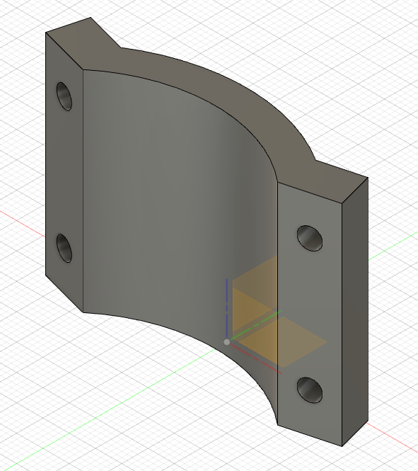
I want to securely attach a digital vernier gauge to my Burly MPCNC to the mounting plate. It would be useful to find a DXF file that I can adapt that has all the screw holes in the right place. I can then work out the fixing for the Vernier Gauge myself.
Looking on Thingiverse shows lots of STL files, but I can’t find a single one that has a DXF file I can use with Fusion 360. Importing an STL file doesn’t give me something I can edit (though that may be an option I haven’t found yet).
Is there an easy way to do this, or do I have to work out all the fittings myself?
To edit the mesh, Turn off design history and then convert the mesh body to brep. That will give you a solid piece.
What part are you looking for a DXF for? Looking at the tool mount, I know I can’t get a DXF because it’s a curved surface. Someone else may be able to.
I just want to design a part in Fusion 360 that bolts onto the mounting plate. As the plate is curved and the M4 holes are at an angle, I thought it would be easier to adapt an existing part rather than using trial and error to get a simple mount made.
Not sure if it fits yet as the printer is busy, I’ll print out later today and check it fits. If it does, I can then extrude out a volume to create an attachment plate.
If it all fits, I’ll upload the f3d file to here, github or thingiverse (blah!) for other people to use.
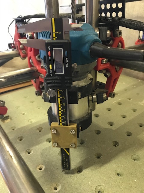
So I made myself a better depth gauge mounting plate that actually fits between the jaws of the Makita tool clamp. I realised that I needed to have the weight of the tool in place otherwise the measurements would be wrong.
I then took depth measurements every 100mm along the X-axis and Y-axis.
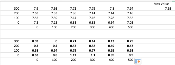
You can see the measurements below in the two tables.
The top table is the absolute depth , the bottom table is the difference from a notional maximum depth which was at (100,300) = 7.93mm. So (0,0) was 0.63mm higher than (100,300)
The greatest difference was at (200,100) with 1.12mm higher. The average variance was 0.53mm.
I am unclear what other people have and whether this is good, bad or simple meh! I’m pretty happy and I think it tells me that I should do a maximum surface run of 1.12mm or more. is that correct?
Very cool. I made some charts on my low rider ages ago and posted them here somewhere. I drilled 2mm deep holes with the machine and then used my calipers to measure the actual depth of the hole and I had a very similar table. I think yours is flatter than mine was, I think I was about 5mm from the highest to the lowest.
fusion 360 <> autocad. Started with the latter in its early DOS version. There has been some change, though. And fusion 360 is also not as simple as some 123-products but it does its job.