THIS is a video of Z being load tested.
3 Likes
Hot end progress…
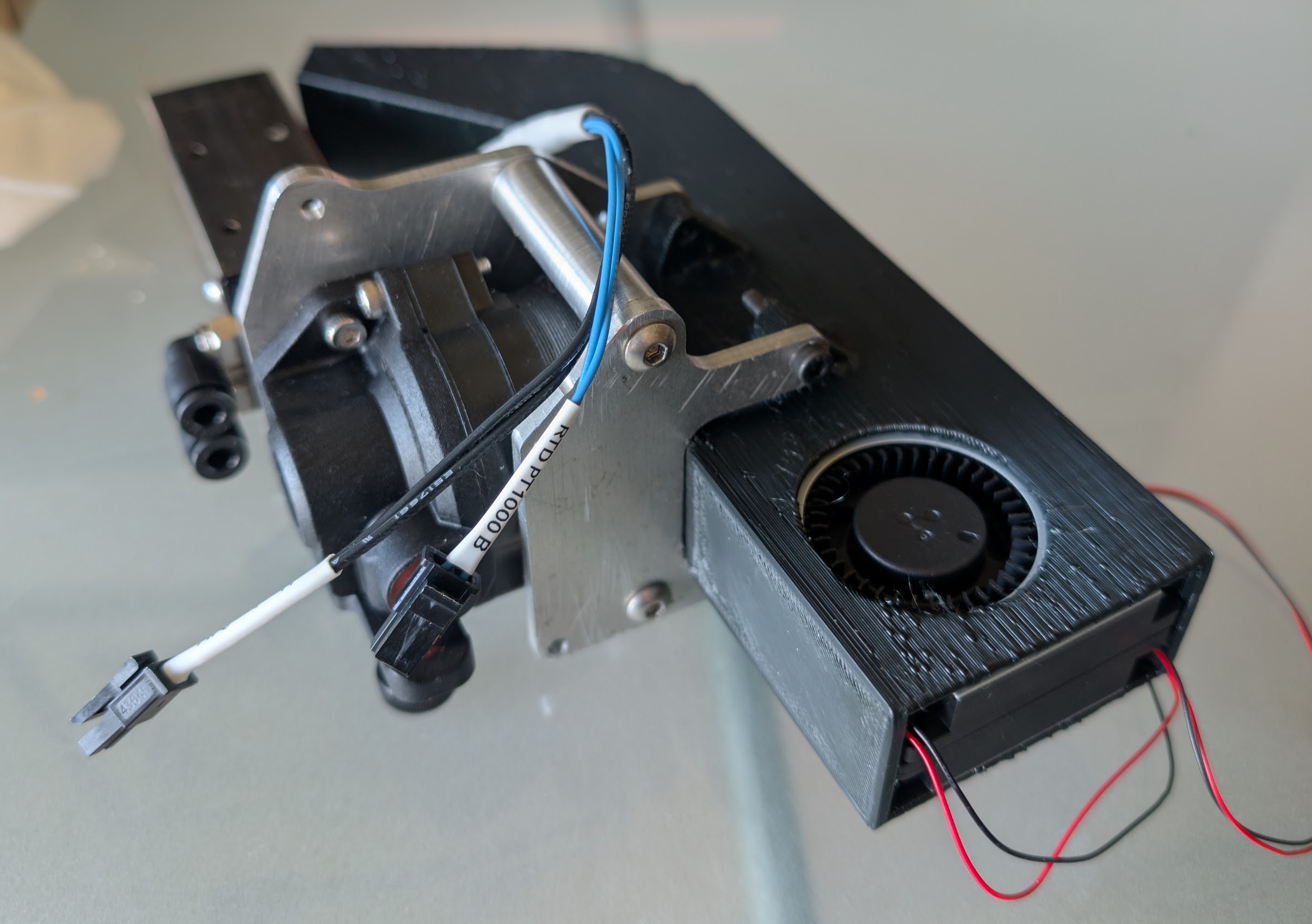
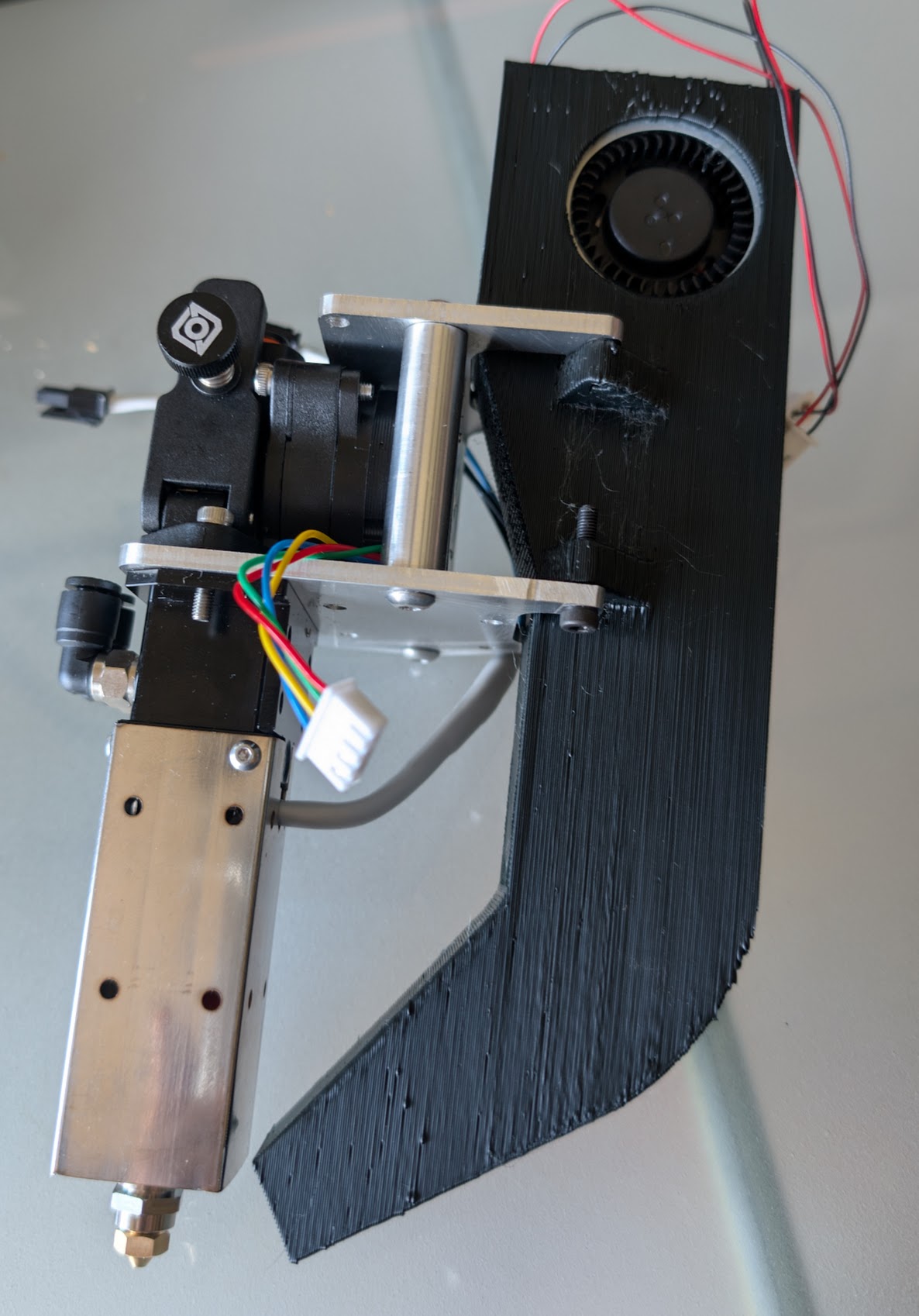
The belts will wrap on the cylinders, and the bottom plate screws directly to the rail carriage (needs countersunk screws).
The top plate is designed to take a bigger fan for part cooling, but I’ll run with the ones that came with the end to start.
The hot end is this one: STD6-LC
I need to figure out the attachment of the Klicky switch next.
The plates were cut and drilled on the MPCNC, 3mm 5083 aluminium.
2 Likes
I got myself in a pickle I bought 2 DM542T drivers on the assumption I’d be able to do simple flying leads from the driver socket on the controller board to the stepper driver, however I’ve run into 2 problems, maybe some of you might have experience with this?
-
The names on the pins are different between the 2 so the mapping is not obvious, and I’ve found nothing on the web to describe such a set up, so now I’m not sure it’s possible, also I found this Stepper Driver Adapter Module which has the right pin out but does not appear to go into a board designed for TMC drivers?
-
What would go in the printer.cfg? I’d assumed if I left that as configured for a TMC5160 then just mapped the pins based on that it’d work, now I’m not so sure.
The controller board is a Fysetc Spdier v1.1
Things have moved on, here’s what it looks like now:
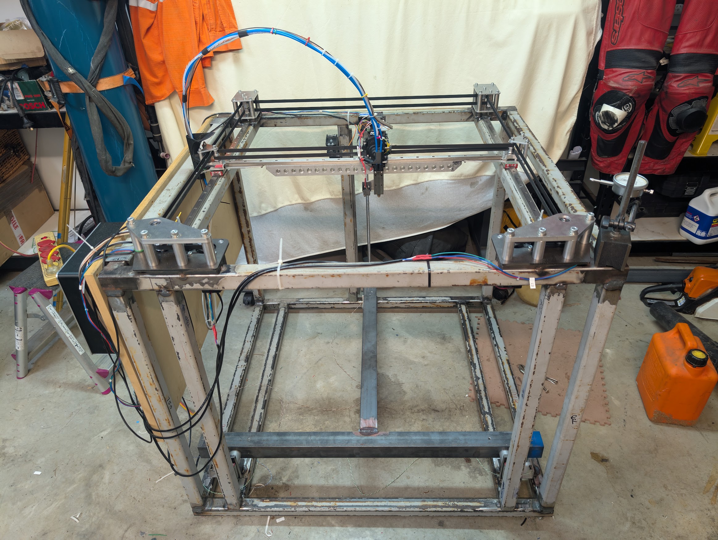
And here’s in moving, doing a Z tilt adjust, nerve wracking stuff when pressing the buttons for the first time.
Big 3D printer Z tilt adjust first runs. - YouTube
There’s a lot more to do with the hardware and code, but it’s getting there.
4 Likes
Heck yeah, that is a beast.
To make first moves less scary I run the steppers at a super low current just in case of a crash. Turn them back up later for speed tests.
5 Likes
Man that thing is a beast!
Man that is a good idea. I don’t ever think of things like that and just watch it crash and then try again LOL. But then again none of my printers are all welded steel frame like this one lol
Man, look at that rail backer!! I used a piece of aluminum angle for mine. ![]()
@vicious1 Wish I’d thought of reducing the current, that’s a great idea.
1 Like
That is pretty amazing!
Extruded aluminum is difficult because it can be easy to knock it out of square, but can be adjusted back into square. If your frame is off just a bit, do you cut and reweld or skew compensate? I can run a bead, but getting things dimensionally accurate proved near impossible when i tried welding. Congrats to you for making this!!
I bet a heavy frame can be a benefit for vibration damping. Are you using z brake for the bed?
@orob I’ve yet to melt plastic, a lot of this is yet to be found out. I put a lot of effort into getting it as flat and square as I could when welding the frame. I’ve a slab of old polished granite counter top for a reference surface, but once I get into calibrating the parts coming off of it we’ll find out if I did a decent job or not.
Trying to keep it flat was mostly lots of clamps when welding and then twisting it back flat again to take out the inevitable movement.
My hope is with the sturdy frame I can run it at speed, otherwise prints this size will take for ever.
1 Like
For sure. Just wanted to seed the question in the hopes you will detail it out as it unfolds. I’m watching with interest and hoping to learn from the shared information.
A couple of videos from the first go at melting plastic:


6 Likes
As I’m writing this I’m sitting in the workshop whilst the printer is a doing calibration prints.
There’s been a few changes since the videos above.
After breaking 3 of the couplers on the right I moved to the type on the left:

I guess the spiral type have torque limitations.
Next was the X Y motors were not giving the performance I’d hoped for, I don’t believe that the TMC5160 in a normal step stick can really push 3A and certainly not for any real time so the machine was not performing and the drivers were overheating.
I replaced the drivers with BTT TMC5160 Plus units like these:
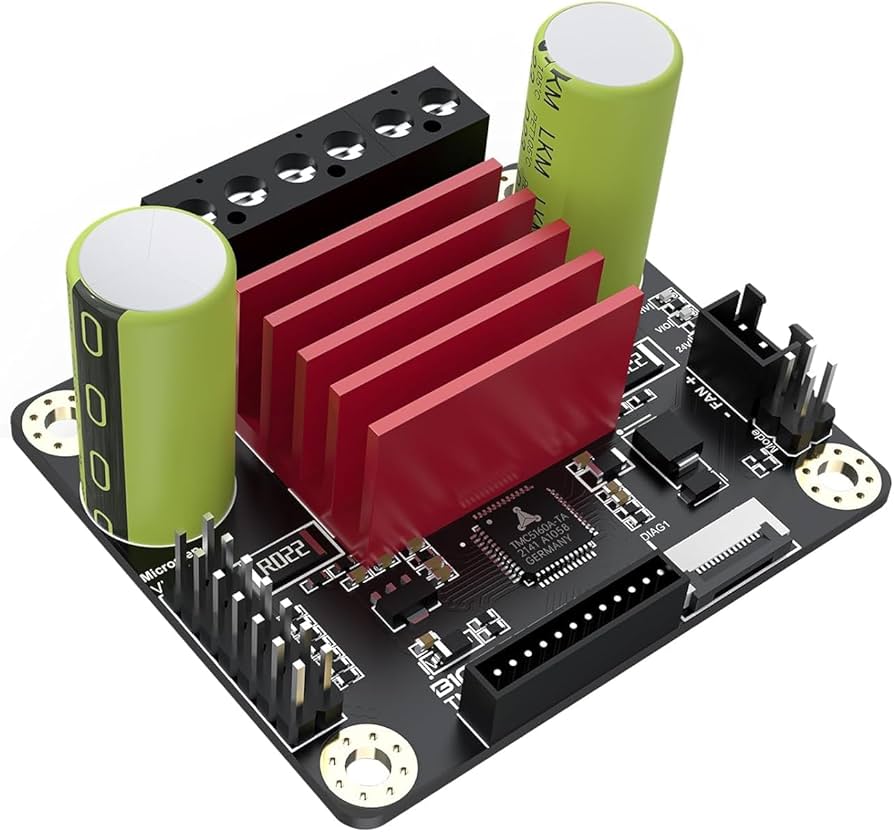
Which can do up to 60V and 10A, and added a separate 48V power supply for these. Now the performance is much better, though I can’t truly say what it is yet as I’m still exploring it and trying not to break stuff along the way. The XY motors run at about 50c allegedly they’ll take up to 80c, so we’ll see how that goes. The metal frame appears to be a pretty good heatsink.
On the wiring front it now looks like this:
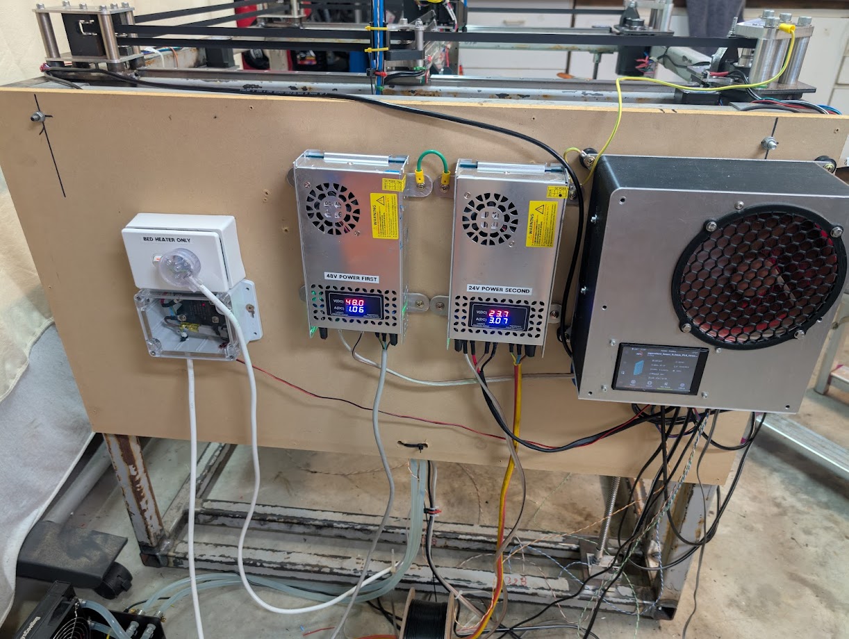
From right to left, first the main box with all the low voltage electronics in, the 24V power supply and the 48V power supply, I like these adjustable units that show the amps as well. Then the mains stuff for the heated bed, it’s a 40A SSR and before it I’ve put a 7A circuit breaker. with 240V and 1,500W it should only use 6.25A at full power, this is all plugged into a power board with a 10A trip, but I wanted the bed to trip before that if it got out of control. There’s also a 130c thermal fuse in the bed assembly.
The TMC2209’s that had been driving the (Nema 17) 3 Z’s were then replaced with the now spare 5160 sticks which then meant I could give the Z motors full power without those overheating either.
I’d used a very long length of Bowden tube to feed in the filament, this was too restrictive, so this was replaced by these little clips that zip to the wires and carbon rod bridging to the hot end:
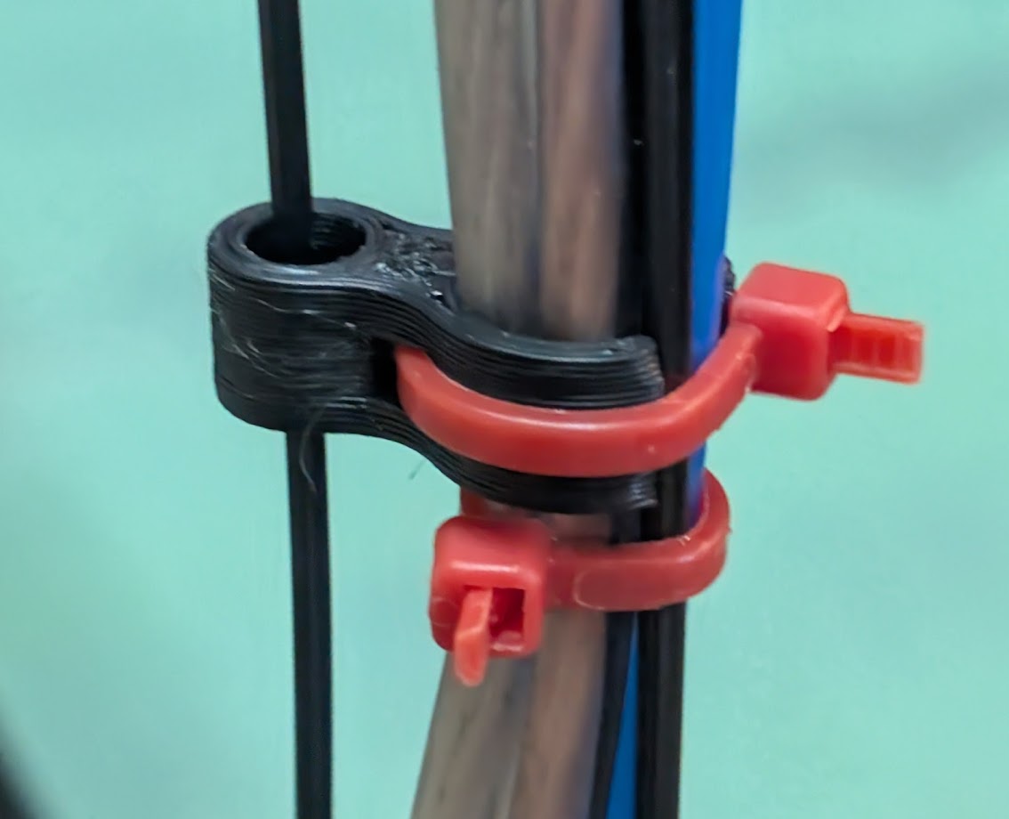
These so far are working nicely, though 6 rather than 4 on the bridge would be better.
The bed is FR10 which PLA sticks to too well I’ve found out, currently trying it unheated, though ambient in the shed is 21c it’s not exactly cold.
The servo that deploys the kickly probe, this thing was a nightmare:
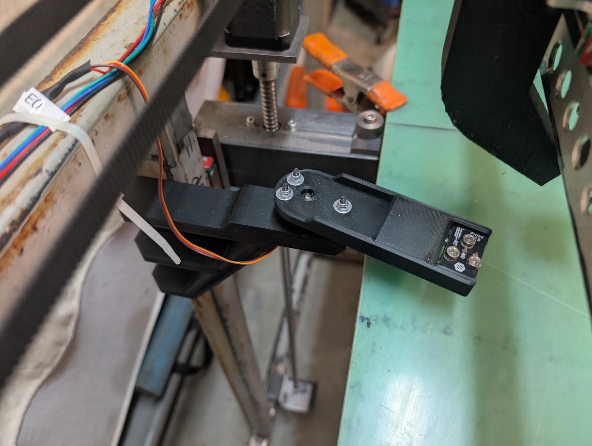
I’d tried driving from different pins on the main board, but inevitably if it was used between 1 and 10 times it would cause a loss of communication between the PI and the main board. Nothing made any sense trying to fix it, in the end I connected it to a Pico and then connected that as another mcu to the PI, one problem solved.
The next problem is the design you see about is crap, there’s about a 60% chance of the probe being deployed and retrieved correctly. The magnets that attached the 2 halves of the probe together are quite strong so push the dock around. This is going to get a redesign.
Lots of tuning to do now.
2 Likes
Wow, that’s impressively big!
so why do you think you are breaking couplers? Weight of Gantry? Are the screws getting bound?
Alignment?
That’d be my guess. That bed looks heavy.
My euclid probe just lives in the back corner of my printer at close to X0 Ywhatever all the way back is. Less moving parts that way. Only thing I need to remember is pull the probe out of the dock if I’m printing something huge that might be close to the dock. Doesn’t happen that often.
Sure, the bed is heavy 10kg+ but the ball screws move easily when everything is lined up.
If the thing were not so big and heavy I’d have put the z motors at the bottom and left the tops of the screws to flap in the breeze like the Vorons do. However, I believed that the heavy bed would damage the motors therefor I did it this way round.
At the bottom there is this:

so what you’re looking at there is the screw is turned down to 8mm and the aluminium sleeve is 10.5mm ID, at the bottom of the hole is a 8mm diameter ball bearing that the screw rests on. With all that being screwed into a 5mm steel plate. So it has some room to move if it wants.
in the middle I left no allowance for misalignment:

But the screws are not murdered up tight just nipped.
At the top the motors are screwed to another 5mm plate that’s welded to the frame. So it’s not going to move.
Obviously, the alignment is not perfect, but its good enough that when all 3 motors are working properly it moves though the whole range of motion without an issue, providing the bed remains relatively level.
Where I think the issues came from, are on occasion during testing one motor would stop, so the whole system got torqued, this would then damage stuff which would fail later. And when the bed is off it’ll drop a bit and not be level as a result so I can hear on a homing run one motor working harder than the others due to this.
Now the kinks are getting ironed out I think I should be past most of these issues.
BTW I made the deliberate choice not to do some sort of system whether Oldham joints or the rat rig thing that can deal with misalignment, at the moment I’m comfortable with that, in a few months time I may have changed my mind if I keep breaking stuff.
You’ve got a great build, and I’ve been watching with interest.
In describing the misalignment you see in homing etc, I predict you’ll keep breaking things.
That setup just isn’t tolerant of the variability it’s encountering.
The other thing you just did is you replaced weak couplers with stronger couplers, so now you’ll discover the next weakest part of the chain or keep breakign the new couplers.
That’s entirely possible but time will tell.
I feel like I’ve got a grip of it now, things initially were a bit out of control as I was starting from scratch. So, we’ll see.