Aaaaaaaaand, ladies and gentlemen, we have a winner. It is @SupraGuy with his well-informed answer that the belts might be too loose. Never would have guessed that, because it is only really noticeable for those cuty, nowhere else. ![]()
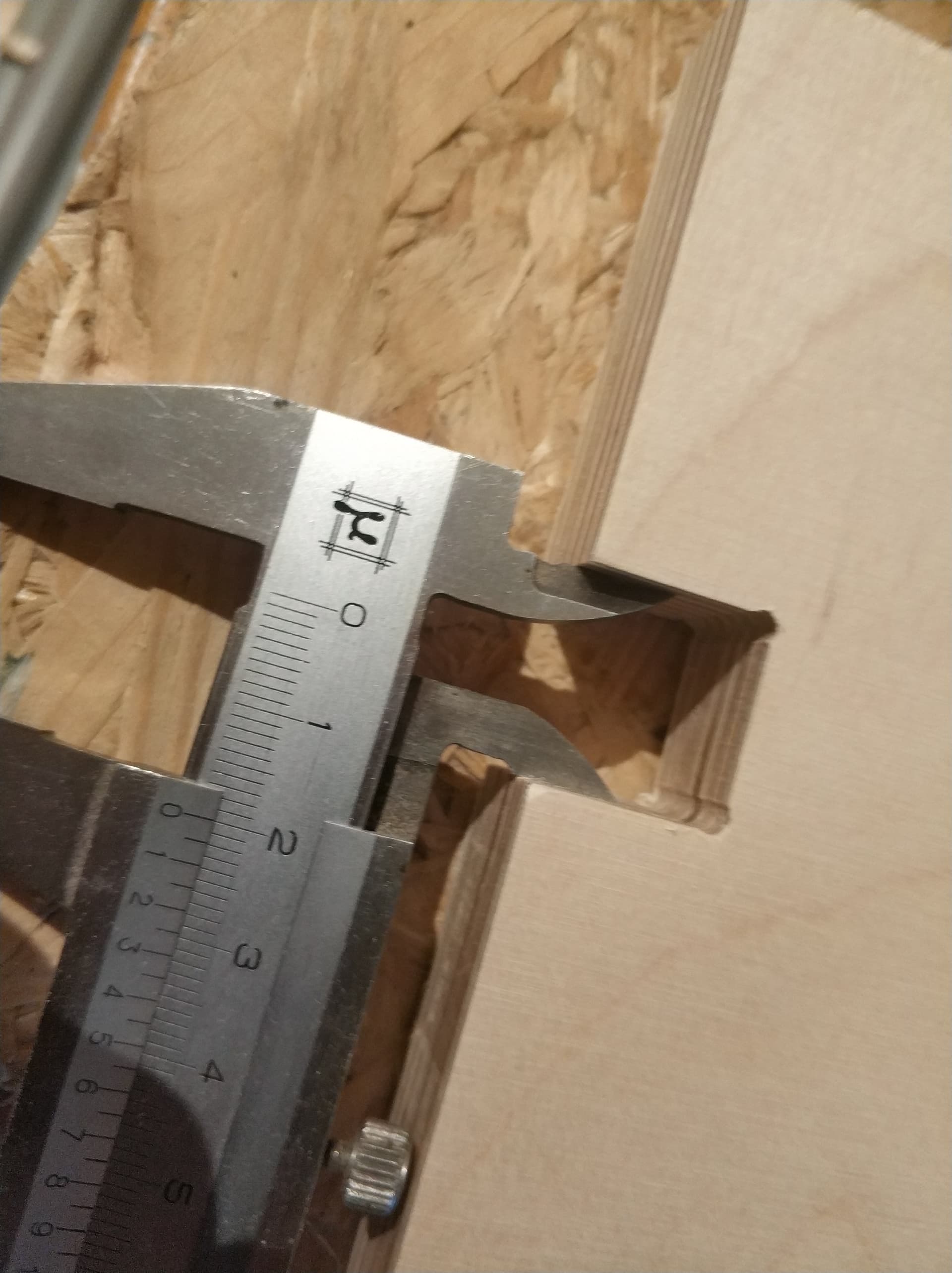
Spot on, you can see the overcut. Thanks so much! ![]()