I built my mpcnc primarily for making PCBs but it will be used for other projects as well. I’ve attempted 3 PCBs so far and just can’t get past the first side on a dual-sided board. I started @ 0.5 which was way too deep of a cut, then went down to 0.3 and still way too deep. Now I’m trying 0.08.
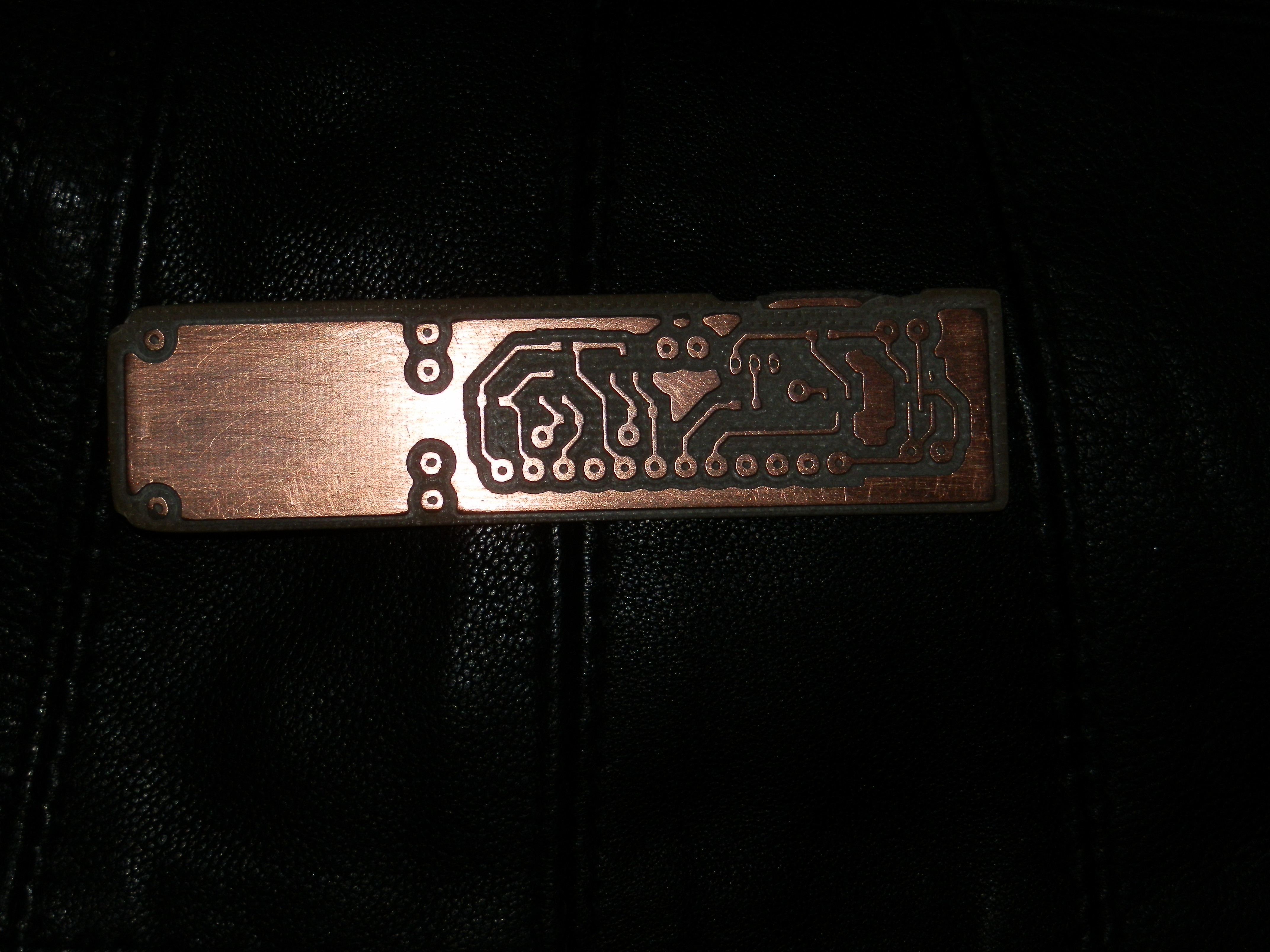
My question is want is the finest increment the mpcnc can do in the Z-axis? I’m using flatcam for the gcode generation and I did manage to get a good result on the 0.3 attempt that is until it came time to do the other side. Attached is an example of the 0.3 board.
My machine controler is a SKR 1.4 turbo and the Zaxis is at 800 steps
800 steps/mm and 1/16th microstepping. So a full step would be 0.02mm. There is some debate about how much accuracy you will really get with microstepping, but most agree it is better than a full step. From just a stepper motor perspective, I would guess 0.01mm or better.
There are other factors. If your mill isn’t heavy enough, you could have backlash. If you have large loads (or a strong plunge) then you might get stuff flexing. A lot of it depends on how accurately you can probe the top surface too, or how level the work is before starting.
The weight of router can actually be a good thing. The Z is lifted by a screw. Screws have backlash. If it sits a bit above its desired height, the weight of the router is what pushes it down against the nut. I have no idea how much force it would take to be essentially perfectly down, but if you have a much lighter router, you might consider buying an anti backlash nut. They usually just add resistance to an already backlash free system. But maybe not for you.
A long time ago, I saw a lot of pcb milling stuff and the common first step was to mill some MDF flat first, so the pcb would always sit on a very flat surface that was parallel to the gantry.
You should be able to probe to get a single Z height with the stock software. Just wire ground to your bit and Zmin (s) to your pcb top surface (just placing a wire there will work) and the. G29 Z to home Z.
Yes I thought about the anti backlash nut. Guess I’ll be Amazon bound again. Great info. Already did the MDF thing along with doing a leveling pass on the actual bed of the machine so that everything is in tune with the gantry. Still working on finishing touches for the machine and at that time I’ll update my first post when its done, but needed to get at least 1 of these boards done first.
TBH, the vertical forces due to engraving pcb traces are very small for most machines. So yeah an anti backlash but should help. With pcb there are many things that affect the cut besides flex. Just variability on clamping can be more than anything caused my the gantry itself. So many pcb mills tend to focus more on the clamping, and also probe leveling. Both of those things when optimized will go farther towards a neat pcb than most other things you can do. Once you have that stuff dialed in, I think you will find stepper resolution is totally adequate even at low microsteppings.
I’ve seen charts with microstepping of commanded position vs real world position, and they tend to look like sine waves with the 0 points landing on full steps. The 1/2 step is usually pretty good, too. This is somewhat misleading though because the peaks of the sine waves are really quite small.
The accurate points on full steps are as stated for the 4 start screws, 200 steps/revolution and 8mm per revolution, so 0.04mm. Use a 1 start 2mm lead screw instead, and that becomes 0.01mm per full step, which ought to be good enough for anyone. Going with a 0.9° stepper motor doubles that full step precision also. IMO, changing to the 1 start lead screw is a good idea anyway, as it tends to eliminate the tendency of the machine to drop the spindle down when the steppers are powered off.
Anti-backlash nuts add a spring, and another nut which cannot rotate independently. It’s not difficult to 3D print something that does this if you don’t want to order anything, or you can look in your parts box.
I you have another leadscrew nut, a spring that fits over that but and some extra long 3mm screws, you can fit the 2 nuts with a spring in between them, then use the extra long 3mm screws through both flanges into the core. This will give you the same effect as the anti-backlash nut. I use anti-backlash nuts on my leadscrew driven 3D printer, but did this while waiting for a replacement when one of them wore out. Because of the springs that I had on-hand (Holley throttle body springs), it actually worked better, but looked fugly, so I put the new anti-backlash nuts in when they came in.
I was just looking at my anti-backlash nuts, and considering how the threaded rod is used on an MPCNC, and in fact on the LowRider2.
Do not use anti-backlash nuts on these platforms
anti-backlash nuts are engineered to put pressure on the nuts such as to force them to the thread side closest to the mounting face. This is done by applying spring pressure against another nut locked into rotational coincidence with the mounting face of the nut.
The MPCNC and LowRider2 both avoid backlash by “sitting on” this face. Therefore the spring pressure would be in opposition to gravity, actually attempting to suspend the gantry against the force of gravity. This means that the spring is reducing the anti-backlash force of gravity (Or gravity is reducing the anti-backlash force of the spring, depending on which is greater.) Either way, you are getting LESS anti-backlash force than you would get with only one of the two in play. Given the designs of both, gravity is the obvious answer as to which of the two you want.
If you insist that gravity alone is not providing enough anti-backlash, then you will have to go with a homebrew anti-backlash nut, similar to what I described in the previous post, but the force of the spring must be set up to attempt to pull the 2 nuts together, not to press them apart, as the anti-backlash nuts are designed to do normally. You could modify the anti-backlash nuts to work this way by clipping the spring that they come with and hooking one end through a mounting hole, and the other around the back side of the flange meant to retain the spring. Perhaps drilling a fine hole on the back of the flange would be effective. This is less reliable long term, but would increase pressure in the desired direction for the nut on the threads.
For this to have any desirable and measurable effect, you would also need to increase the clamping force between the core of an MPCNC and the face of the nut as well. As it is, those screw holes are only meant to prevent the nut from rotating.
Edit: actually, there’s an easier solution, which is to add a spring tensioned between the core and the Z motor mounts, pulling the Z axis downwards. This would more firmly seat the mounting nut into the core and reduce available backlash with the threads. It would increase the tendency of the spindle to fall when the steppers are turned off though.
The Genmitsu blue 0.1, 30 degrees V bit. I also have the multi-bit pack from 0.8 to 3 mm along with multiple Dremel bits varying from.1 to 3 mm. I’ve been using the V bits for the boards. I have that board running right now @ 0.8 using a 0.1 V-bit. Looks good so far.
I just swapped a 4 start leadscrew for a 1 start, and noticed the backlash hasn’t changed much on my primo. I was secretly hoping the thread tolerances would be similar so backlash would drop, but it is what it is. My main reason for the 1 start is safety during e-stop (my z dropped fast every time). My flyweight Bosch Colt doesn’t help on the backlash front. I mostly use spiral upcut bits and am conservative on DOC, but still I wonder if “heavier backlash resistance” would improve performance for me.
I get what Dan is saying about anti-backlash nuts on the current design. To me it looks like there is enough meat on that area of the core to increase the bore diameter and depth for the z-nut, in order to fit an anti-backlash nut upside down? This would of course effectively make the router “heavier” on the screw WRT backlash control. I have a s**t ton of really cheap filament I can get rid of, and I’m about to burn up a spool for such an upgrade. Gotta think of any other potential core mods before I do though.
Ryan, not sure how much work it would take to spin up an stl with a cylinder cut on the z-nut hole? I gotta ask… cause I’m OCD enough where remixed STL meshes bug me, lol (and too lazy to RE all those details).
[edit: Just played with a simple remix and it’s going to be more challenging than I thought originally. The diameter of the spring part of the nut is big enough to overlap with the 4 mounting holes. So it would require something like slotting 4 holes on the nut and moving the core mount holes farther out. Doable, but like 10x the work to remix than I thought, and definitely can’t just be drilled into a stock core.
edit2: Even more complex, as the larger center bore opens a hole in the top core clamp bearing hole bay. I added some filler there without interfering with bolt install… should work now.
I went ahead and measured the weight of my z gantry with a luggage scale, and I hear the nut click over when I get to about 142oz. For those not familiar in oz, that’s just shy of 9 pounds. This is with a somewhat tall J primo (150mm Z), with 0.125 wall DOM, a mister with clunky metal flex hoze, and a Bosch Colt w/ my sorta clunky mount/vacuum setup. That has a few things going for it vs say one with like 50mm Z travel built with conduit and not mister/vacuum. My birds eye guess is this accounts for ~40oz extra weight on my gantry vs a typical short z conduit build. Still, 140oz doesn’t feel like much to me… the rest of the framing seems to be holding solid at that point anyways (but I really need to invest in a dial guage to quantify such claims).
I measured the installed length spring force for a few stock Tr8x4 backlash nuts I have on hand. Ryan and everyone else who said these would be of little help were correct… ~40oz more is all you’ll get, which is nothing for a mill. I found a spring with a lot more k in my spares box, which just so happened to fit the nuts well. I cut it such that I got 160oz of load out of it (installed length). This would mean my gantry won’t ‘click up’ until lift loads surpass 18 pounds.
That seems adequate to ensure I’m getting max load out of the framing… but jury is out on how long my nuts will last. I recently went to a 1 start T8, and have 2 brass and 2 POM anti backlash nuts coming this week. Guessing greased brass will be best here, but cheap enough to try the POM. My modified core just finished printing and looks very good (y’all are gonna fall in love the color I used, hehe). I might be in a position to get photos and put it to the test this weekend. Will take some tests to see… but I’m hoping to get better plunge performance, as well as ability to use a downcut once in a while.
[edit: DOH! I think I cut my new lead screw prematurely. That anti-backlash nut I think is going to slip off the end when move Z to the top. So I’ll have to order another screw and cut it about 1.5" longer than stock to work with this.]
The Z motor has to lift those 9 pounds and overcome and downward force from milling, and now the added friction of the anti backlash nut. My guess is that is the limit before you manage to lift the Z gantry.
The motors also lose torque as they go faster. Changing to a 1 start screw makes the Z have to turn faster. So you probably have more torque at slow speeds, but when you speed up, you will end up with less (10mm/s is probably too fast for a 1 start screw). And that limit will get even lower if you start adding a bunch of friction because of a tight nut. Skipped steps are in your future.
What are you actually trying to solve? You can easily lift 9 pounds. But why does the router have to? On a roughing pass, where you are chewing through material, you will leave a little material if you somehow manage to reach 9 pounds of vertical force. On a finishing pass (where accuracy matters), you will have nearly zero force from the bit.
It may be I’m just roughing too fast, IDK. When I was cutting that 2" thick alum project recently, there were a few moments where I could see the router freely drop down as it walked “off a ledge”. After that job, I noticed a cracked z-motor mount. You’d think that would have something to do with that, lol. I wasn’t sure though since most of that slop seemed to come from the nut, not flex in the cracked mount.
So here I am, modified core printed out, POM antibacklash with stiff spring installed, got it all squared/trammed… now just gotta test it. I 100% agree with your concern over friction and skipped steps. That’s why I decided to use the POM nut, since the brass even when oiled was just too sticky IMHO. After getting it all tightened/squared, I shut it down and manually rotated the z-nut. Y’know what, it’s actually as easy to turn as when you lift with a 4-start. Go figure… POM works really well… just hope it lasts a year or 2 (doesn’t appear to be getting shredded or anything, but it’s my first POM nut).
Also on the upside, my new core bolted up seemingly a lot stiffer/straighter than the my first one. So now the x/y are also feeling very much rock solid. It’s as close to a bridgeport as it’s ever felt, lol.
I also understand my z rapids will have to be 4x slower, and that may really suck on deeper/longer operations. There’s only so many steps/sec the drivers can do. I’ve got drv8266 though… think I could go faster with tmc2209? I tend to be impatient with these kind of things… so this could be a deal breaker for 1-start for me.
I got curious and decided to measure stall loading for z lift, and I got around 12-13lbs before the motor started to skip (crude off angle method required since my luggage scale doesn’t hold max, and the display faces down during measurement… so actual load is likely more than 13lbs). Unfortunately, I did not test this without the spring in place. So no telling how much overhead was lost. However 12lbs of lift before stall seems like a lot. Guessing that’s going to be on par if not better than 4-lead without a spring.
You think that’s enough headroom to go ahead with my plan to upgrade the colt to a 65mm h20 spindle (I believe those are 2-3lb wet)?
I’m still kinda on the fence about aluminum. Yea, we can cut it, slowly, but this machine wasn’t really designed to mill aluminum. It’s more of a “my first CNC” that you graduate to a larger machine when you decide you like the process. We’ve had a couple folks do this. I’m still amazed how well the part you made came out though.
Just wanted to provide updated info here… my experiment with the anti-backlash nut turned out as Jeff expected… skipping steps did end up being hard to stop at speed. Fortunately, not sure why yet, it seems my z with the new setup has a lot less backlash even without the spring. Only thing I changed was the motor mount, core clamps, and spindle mount. Wondering if it’s because I’m still using the POM nut with my modded core… maybe skewing threads enough to reduce the backlash?
Anyhow, it’s stable now using 700mm/sec, 12V, tmc2209 1/16, with the 1-start. Interestingly, I couldn’t get any more speed out of it using 1/4 steps with my drv8825’s. 1/16 seemed the same as far as torque loss, but of course higher res. That being the case, I just popped in some 2209’s to modernize it a bit. 24V is on the way… that will of course bring up the speed.
@barry99705 , I get what you’re saying, but I think the step of graduating to a larger machine is often so expensive that it becomes the line that separates hobby/pro. I worked at a pro machine shop for some time, so I’m familiar with the capabilities, requirements, costs, etc. It was fun dodging chips flying off a 3" flycutter blowing through a 5lb block on a bridgeport, or watching the haas hogging “phantom tits” out of UMHW for medical research use… but those clients were also paying huge for those parts. Otherwise, having a $20k setup in the garage to suit occasional hobby desire is just too tall a fence to jump over for most folks. That’s why I think we see so many pushing the little engine that could farther up the hill… it’s a fun journey anyways, that I think everyone should try at some point (cutting alum on their mpcnc).